
Basic Circuit
Index 340
STEPPER_MOTOR_AS_SHAFT_ENCODER
Published:2009/6/24 2:59:00 Author:May
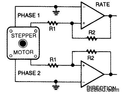
To use a stepper as a shaft encoder, the out-put signals must be converted to square waves with a pair of voltage comparators. (View)
View full Circuit Diagram | Comments | Reading(0)
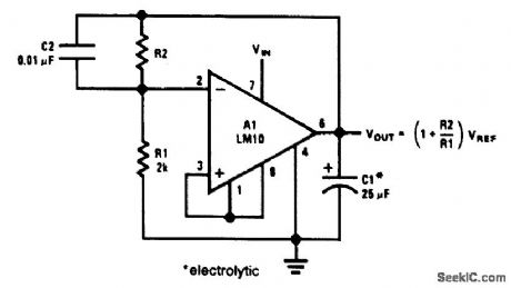
ADJUSTABLE_POSITIVE_REGULATOR
Published:2009/6/24 2:57:00 Author:May
View full Circuit Diagram | Comments | Reading(0)
POLARITY_GAIN_ADJUSTMENT
Published:2009/6/24 2:53:00 Author:May
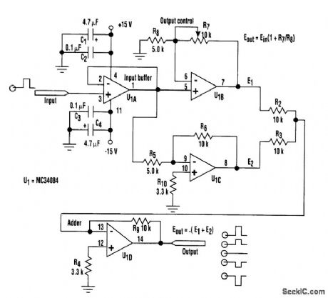
By adjusting one potentiometer, this circuit's output can be varied from a positive-going version of the input signal, smoothly through zero output, then to a negative-going version of the input (see the figure). If the input signal is a positive pulse of, for example, +2-V peak, the output pulse amplitude can be smoothly varied from +2-V through ground (no output) to a -2-V peak.
Taking a closer look at the setup, assume that the signal has a +2-V peak input. The A section of the quad op amp is an input buffer, op amp C provides a fixed negative-going output of -4-V peak, and op amp B supplies a positive-going output that varies from +2-V to +6-V peak. The D section adds the B and C outputs. Thus, by varying the B output, the circuit output varies smoothly from -2-V to +2-V peak.
The circuit can, of course, also be used as a 0°/180° phase switcher. For instance, with a groundcentered sine-wave input of 4V p-p, the output varies from 4-V p-p in phase with the input, smoothly through 0 V, to 4V p-p 180° out of phase with the input. (View)
View full Circuit Diagram | Comments | Reading(889)
SHARP_SQUARE_WAVEFORMS_FROM_MULTIVIBRATOR
Published:2009/6/24 2:50:00 Author:May
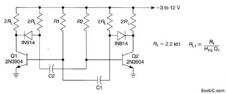
By using diodes as shown, the loading effect on the collector of the transistors caused by the tim-irtg capacitors can be avoided. As the collector of the transistors rises toward VCC the diode discon-nects the tinting capacitors. (View)
View full Circuit Diagram | Comments | Reading(0)
RECEIVER_AF_NOISE_LIMITER_FOR_LOW_LEVEL_SIGNALS
Published:2009/6/24 2:46:00 Author:May
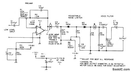
A preamplifier in the audio frequency range amplifies a noisy audio signal to drive a diode clip-per. Suitable audio input levels would be in the 10-mV to 1-V range. (View)
View full Circuit Diagram | Comments | Reading(0)
GUNSHOT_SOUND_EFFECTS_GENERATOR
Published:2009/6/24 2:46:00 Author:May
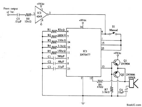
Gunshot sound-effects generator built around a Texas Instruments SN76477 sound chip. An in-put pulse causes IC1 to generate a gunshot sound. (View)
View full Circuit Diagram | Comments | Reading(0)
ELECTRONIC_WIND_CHIME
Published:2009/6/24 2:45:00 Author:May
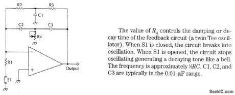
The value of R4 controls the damping or decay time of the feedback circuit (a twin Tee oscillator). When S1 is closed, the circuit breaks into oscillation. When S1 is opened, the circuit stops oscillating generating a decaying tone like a bell.The frequency is approximately 1/2 RC. C1, C2, and C3 are typically in the 0.01-μF range. (View)
View full Circuit Diagram | Comments | Reading(0)
ELECTRONIC_WHISTLE
Published:2009/6/24 2:42:00 Author:May
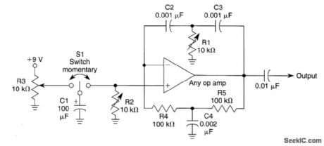
The circuit shown is a twin-tee oscillator. R1 varies the pitch, R2 the duration, and R3 the for-mat (bell, rise 8u fall time, etc.). Vary R4, R5, C4 and C2, C3 for large shifts in frequency. (View)
View full Circuit Diagram | Comments | Reading(825)
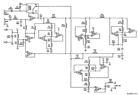
AUDIO_DYNAMIC_NOISE_REDUCTION_SYSTEM
Published:2009/6/24 2:41:00 Author:May
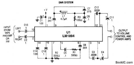
U1 is a dedicated IC (National Semiconductor) that achieves up to adaptive bandwidth scheme and a psycho acoustic masking technique. (View)
View full Circuit Diagram | Comments | Reading(1479)
VARIABLE_VOLTAGE_REGULATOR_WITH_CURRENT_CROWBAR_LIMITING
Published:2009/6/24 2:40:00 Author:May
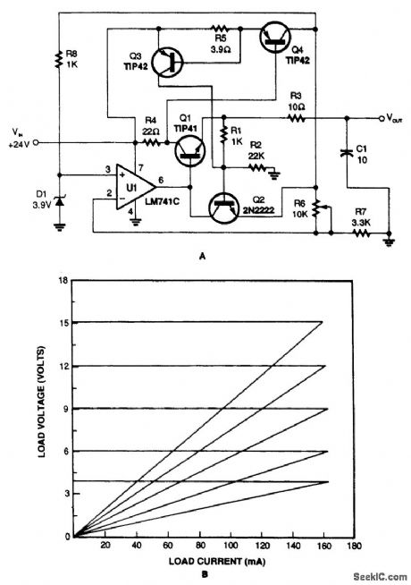


The variable voltage regulator with current-crowbar limiting, shown in Fig. 71-1A, overcomes the disadvantages of constant and foldback limiting. As you can see in the graph (Fig. 71-1B), the current crowbar quickly shuts down the supplied power when a preset current is exceeded. It also has excellent load regulation over its operating range. (View)
View full Circuit Diagram | Comments | Reading(1179)
TONE_ENCODER
Published:2009/6/24 2:35:00 Author:May
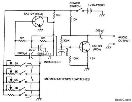
A basic twin-T circuit uses resistors for accurately setting the frequency of theoutput tones, selected by pushbutton. Momentary switches produce a tone only when the button is depressed. (View)
View full Circuit Diagram | Comments | Reading(0)
CW_IDENTIFIER_WITH_SINE_WAVE_AUDIO_OUTPUT
Published:2009/6/24 2:29:00 Author:May
This identifier can be used to drive a hidden transmitter in a radio fox hunt activity, where the object is to locate a hidden transmitter. (View)
View full Circuit Diagram | Comments | Reading(0)
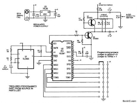
MORSE_MESSENGER
Published:2009/6/24 2:19:00 Author:May
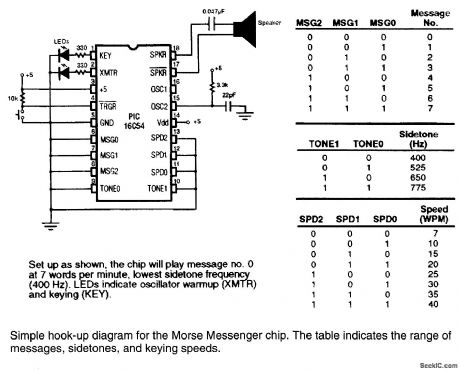
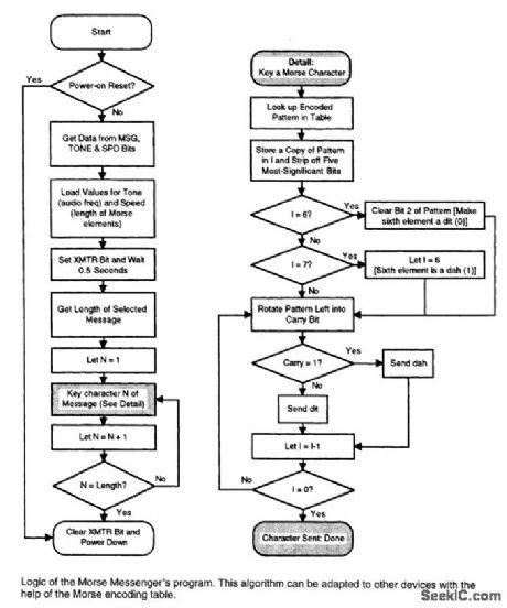
This keyer uses a PIC16C54 micro-controller to generate a Morse code message. The microcon-troller must be programmed to suit users call IC or desired message. (View)
View full Circuit Diagram | Comments | Reading(2088)
PASSIVE_MIXER
Published:2009/6/24 2:19:00 Author:May
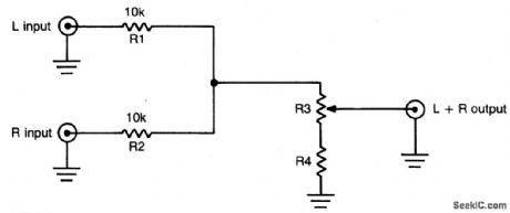
This simple circuit can be used to combine stereo signals to produce a mnaural output. R1 and R2 isolate both circuits and R3 controls the level of the combined output signal. (View)
View full Circuit Diagram | Comments | Reading(907)
ACTIVE_CW_AUDIO_FILTER
Published:2009/6/24 2:16:00 Author:May
The audio filter shown has a bandpass of 200 Hz centered on 700 Hz. Resistors are 1% tolerance and capacitors should be 5% tolerance. (View)
View full Circuit Diagram | Comments | Reading(964)
CMOS_MIXER
Published:2009/6/24 2:13:00 Author:May
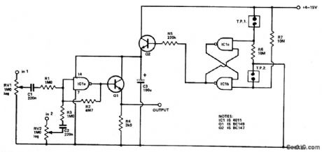
Four inputs can be mixed by duplicating the circuit to the left of C3 and using the fourth gate of IC1. Two gates are used in a touch-operated switching circuit that controls the voltage on the base of switching transistor Q2. Touching TP1 and TP2 alternately turns the circuit on and off. (View)
View full Circuit Diagram | Comments | Reading(787)
TWO_CHANNEL_PANNING_CIRCUIT
Published:2009/6/24 2:12:00 Author:May
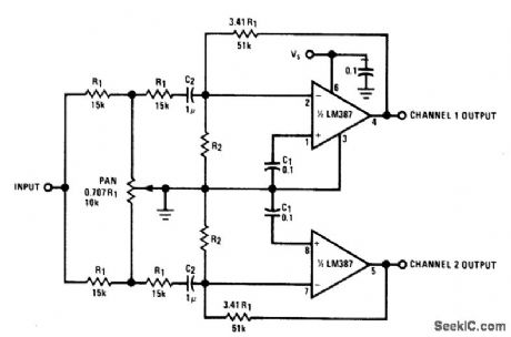
This panning circuit (short for panoramic control circuit) provides the ability to move the apparent position of one microphone's input between two output channels. This effect is oftern required in recording studio mixing consoles. Panning is how recording engineers manage to pick up your favorite pianist and float the sound over to the other side of the stage andback again. (View)
View full Circuit Diagram | Comments | Reading(2359)
HIGH_LEVEL_FOUR_CHANNEL_MIXER
Published:2009/6/24 2:07:00 Author:May
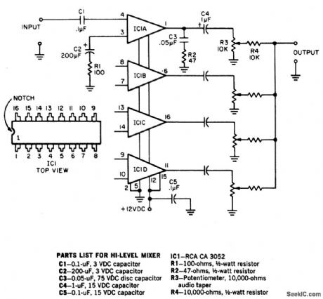
To provide good signal-to-noise ratio,this four channel mixer amplifier controls the signal levels after the amplifiers,and then mixes them to offer a combined output. The circuit works with any 50 ohm to 50 K dynamic microphone but not with crystal or ceramic mikes because the IC input impedance is low. Note that all four circuits are identical but that only one is shown complete. (View)
View full Circuit Diagram | Comments | Reading(1048)
FOUR_INPUT_STEREO_MIXER
Published:2009/6/24 2:05:00 Author:May
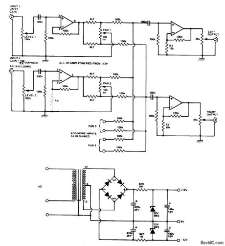
Four (or more) inputs can be mixed and produce stereo output. Gain of each stage can be boosted by adding RX, but it should be kept below 50 (RX above 2.2 K) to avoid poor fre-quency, response. If more than four stages are used, decrease RX to 6.8 K for six inputs, or 4.7 K for eight inputs. The op amps are 741 or other lower noise types. The power supply circuit is also given. (View)
View full Circuit Diagram | Comments | Reading(1009)
Instrument and Signal Circuit Principle Diagram of Liberation CA6400 Series Light Buses
Published:2011/7/22 21:54:00 Author:Michel | Keyword: Liberation, Light Buses, Instrument, Signal, Principle Diagram
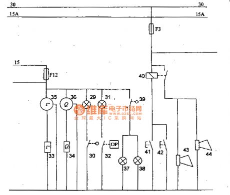
Picture:Instrument and Signal Circuit Principle Diagram of Liberation CA6400 Series Light Buses
29-manual indication lights,30-switch of manual indication lights,31-hydraulic warning lights ,32-hydraulic alarm switch,33-temperature sensor,34-fuel table sensor,35-temperature table,36-fuel table,,37and 38-backup light,39-switch of backup light,40-horn relays,41and 42-horn button,43 and 44- claxon. (View)
View full Circuit Diagram | Comments | Reading(849)
| Pages:340/471 At 20321322323324325326327328329330331332333334335336337338339340Under 20 |
Circuit Categories
power supply circuit
Amplifier Circuit
Basic Circuit
LED and Light Circuit
Sensor Circuit
Signal Processing
Electrical Equipment Circuit
Control Circuit
Remote Control Circuit
A/D-D/A Converter Circuit
Audio Circuit
Measuring and Test Circuit
Communication Circuit
Computer-Related Circuit
555 Circuit
Automotive Circuit
Repairing Circuit