
Basic Circuit
Index 341
12V-24V Voltage Conversion Start System Circuit of Toyota Coaster
Published:2011/7/22 21:52:00 Author:Michel | Keyword: Toyota Coaster, Voltage Conversion , Start System Circuit

Fifth,12V-Z4V Voltage Conversion Start System
Coaster coach circuit often uses 12 V system or 24 V system. Some models are 12 V system but they adopt 24 V to start the machine.24V starter is used when the 12V diesel engine feels that 12V start power is not enough.If other electrical system such as generator, electrical equipment are still 12 V,two batteries are needed. 1 and 2 are usually in a parallel state,they bear 12 V generator charge or provide power supply for 12 V power equipment system.When it starts up, two batteries voltage conversion relay reach a 24 V in series way and provide power supply to the starter.When starting is over, voltage conversion relay makes two batteries become parallel connetcion way. And the circuit connection is shown as figure 7.
(View)
View full Circuit Diagram | Comments | Reading(3103)
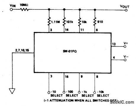
PROGRAMMABLE_ATTENUATOR_1_TO_00001
Published:2009/6/24 2:03:00 Author:May
View full Circuit Diagram | Comments | Reading(699)
VARIABLE_ATTENUATOR
Published:2009/6/24 2:00:00 Author:May
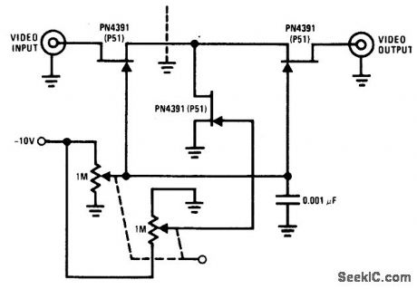
The PN4391 provides a low Rds(on) (less than 30 ohms). The tee attenuator provides for optimum dynamic linear range for attenuation and if complete turn-off is desired, attenuation of greater than 100 dB can be obtained at 10 MHz providing proper rf construction techniques are employed. (View)
View full Circuit Diagram | Comments | Reading(979)
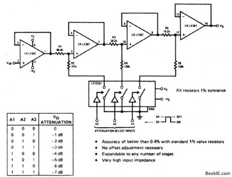
DIGITALLY_SELECTABLE_PRECISION_ATTENUATOR
Published:2009/6/24 1:58:00 Author:May
View full Circuit Diagram | Comments | Reading(824)
4 Road Temperature Monitoring Circuit of Thermistance
Published:2011/7/22 21:50:00 Author:Michel | Keyword: Thermistance, 4 Road, Temperature Monitoring
The picture 3-12 is 4 roads temperature monitoring circuit compsoed of thermistance etc.This circuit sets the thermistors RPl-RT4 in 4 places (chA, chB, chCand chD)in the test site and monitors the temperature of the 4 places.RP1 and RP2, RP3 and RP4, RP5 and RP6, RP7 and RP8 set the high and low temperature of chA,chB,chC and chD respectively.It uses time-slice method to switch RT1 and RT4 order and the temperature range is set between high and low temperature.It is input to window comparator and is judged and the judgement result is locked and output.NE555 and MC14027 (1), MCl4027(2) decide the switch frequency and the switch frequency is about 1Hz according to the device's parameters. (View)
View full Circuit Diagram | Comments | Reading(474)
MELODY_CIRCUIT
Published:2009/6/24 1:56:00 Author:May
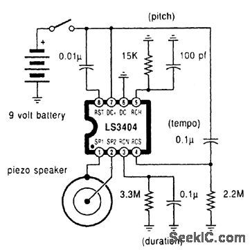
A high-quality melody circuit. The slow decay waveform produced will create chime-like notes. Pitch, tempo, and duration are all adjustable. (View)
View full Circuit Diagram | Comments | Reading(1338)
MUSICAL_INSTRUMENT_DIGITAL_INTERFACE(MIDI)TRANSMITTER
Published:2009/6/24 1:54:00 Author:May
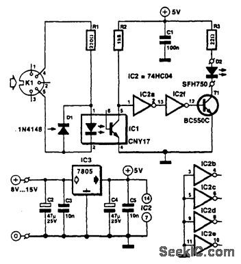
Used for digital control of musical instruments, this transmitter converts the digital data signals to equivalent optical signals for fiberoptic cable interface. Optocoupler IC1 provides isolation, and drives IC2-a and -b and T1, and finally provides a cable driver LED (SFH750). (View)
View full Circuit Diagram | Comments | Reading(2023)
HV_REGULATOR_WITH_FOLDBACK_CURRENT_LIMIT
Published:2009/6/24 1:46:00 Author:May
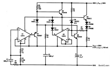
The output current issensed across R8, This is delivered to the current-limit arrtplifier through R7, across which the foldback potential is developed by R6 with a threshold determined by D4. The values given limit the peak power below 20 W and shut off the pass transistors when the voltage across them exceeds 310 V. With unregulated input voltages above this value, start-up is initiated solely by the current through R5. Q4 is added to provide some control on current before A2 has time to react.The circuit is stable with an output capacitor greater than about 2 μF. Spurious oscillations in current limit are suppressed by C2 and R4, while a strange, latch-mode oscillation coming out of current limit is killed with C1 and R1. (View)
View full Circuit Diagram | Comments | Reading(1298)
Linear Circuit of Thermistors
Published:2011/7/22 21:42:00 Author:Michel | Keyword: Thermistors, Linear
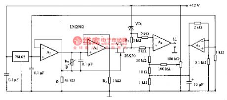
The picture is thermistors linear circuit.This circuit is also constant current source circuit and its same phase input port's benchmark voltage is provided by 78LO5.A2 output provides a constant current for thermistors RT and the current enters the ground via R1.Constant current value depends on Rl resistance. If the resistance RT is 5kΩ,the voltage on RT decreases to 0·6V and the constant current is 120 μA. The voltage is added to the VT1 source through the A3 buffer.R2's function is that it makes A3 output voltage keep constant when it flows through invalid current and VT1 source current alters.R3 voltage and temperature on two endsare linear relationship but R3 is float state.Thus,the differential amplifier A4 takes out the voltage and outputs voltage U.It and the temperature become linear relationship. (View)
View full Circuit Diagram | Comments | Reading(860)
PWM Benchmark Voltage Generating Circuit
Published:2011/7/22 21:41:00 Author:Michel | Keyword: Benchmark Voltage, Generating Circuit

The picture is PWM benchmark voltage generating circuit.In the ciruit,74HC161(1) and 74HC161(2) are four binary counters.Once the clock signal CLK inputs 256 pulses and it outputs、 instructions and trigger 74H04 are set in advance.74 HC191 (1) and 74 HC191 (2) are the subtraction counters.74 HC161 (1) carry instruction makes voltage data load and decreasingly count.4 HC191(1) carry instruction makes the trigger 74HC74 reset and setting and resetting time become relative to their data. Step voltage is lOmV, R2 short-circuits. (View)
View full Circuit Diagram | Comments | Reading(920)
High Precision PWM Wave Generating Circuit
Published:2011/7/22 21:39:00 Author:Michel | Keyword: High Precision, PWM Wave, Generating Circuit
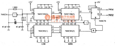
The above picture is high precision PWM wave generating circuit.This circuit uses the number and data to control the dutyfactor accurately and constantly in 1%~99% range on the basis of 1% step.It can be used as calibration and adjustment PWM demodulation circuit or used as D/A converter sources D/A converter sources in PWM way.74 HC04 inverter and X1 (2 MHZ) constitute the crystal oscillator circuit and its work is very stable and the highest work frequency is 2MHZ.74 HHC190 (1) and 74 HCl90 (2) demodulate and get 20KHZ clock frequency.Once 74 HC190 (2) outputs 100 clock pulse it triggers the bistable multivibrator 74 HC74 one time.Reset method is that using comparators 74 HC85 (1) and (2) 74 HC85 to set.The clock pulse stops counting, circuit resets 74H04 outputs dutyfactor wave which is equal to setting value and the waveform resolution is 1%.
(View)
View full Circuit Diagram | Comments | Reading(1576)
Metal detector 3
Published:2011/7/29 2:45:00 Author:Ecco | Keyword: Metal detector
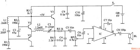
This metal detectors described in the example can be used as finding location of underground metal pipes, removal and the detection of metal garbage in beach swimming pool and residual nail in wood.The working principle.The metal detector is composed of detection oscillator, reference oscillator and audio amplifier and other components, it is shown in Figure 8-69.
Detection oscillator consists of transistors Vl, V2 and detection coil Ll, capacitor Cl and so on. Reference oscillator consists of transistors Vl, V3 and inductor, capacitor C3 and other components. Audio amplifier audio is composed of power amplifier IC, the volume potentiometer RP and capacitors C6-C8 and so on. Before the end of Ll detecting metal objects, the operating frequency of detection oscillator and reference oscillatorare the same (are aboout 32OkHz), the emitter of V3 has no audio signal output, speaker BL has no sound. When the metal in the ground is detected by Ll, the detection oscillator frequency will become higher, V3 emitter outputs an audio signal, which is amplified by the lC to drive the audio speaker BL, and it issues calls to remind the user metal objects have been detected . (View)
View full Circuit Diagram | Comments | Reading(4129)
Metal detector 6
Published:2011/7/29 2:47:00 Author:Ecco | Keyword: Metal detector
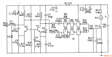
The metal detector circuitis composed of thedection oscillator, reference oscillator, the oscillation signal processor, mixing amplifier and ammeter PA and other components, it is shownas Figure 8-72.
The working principle.Detection oscillator is composed of the oscillating tube Vl, exploring coil Ll, Cl-C4 capacitors and resistors Rl-R3 and so on. Reference oscillator is composed of the oscillating tube V2, inductor L2, capacitor C6-C9 and resistors R2-R4 and so on. Oscillation signal processor consists of six non-door (Dl-D6) integrated circuit IC and the external RC components. Hybrid amplifier is composed of a diode VD, resistors Rl2, R13, capacitor C13 and field-effect transistors VF. Turning on the power switch S, both the detection oscillator and reference oscillator start oscillation, the collector of Vl and V2 outputs two same frequency sine wave oscillation signals, they are amplified and transform processed by the oscillation signal processor to become two square wave signals with same frequency and amplitude and opposite phase, then mixed by RlO, RlI and VDl and sent to the the gate of VF. Before Ll detecting metal objects, the two square wave signals are with the same frequency, phase reverse, VF's gate voltage drops below 2.5 V, VF does not work, PA ammeter indicates 0 (ammeter pointer refers to the scale plate in the middle.) (View)
View full Circuit Diagram | Comments | Reading(2935)
ONE_SHOT_MULTIVIBRATOR
Published:2009/6/23 22:34:00 Author:May
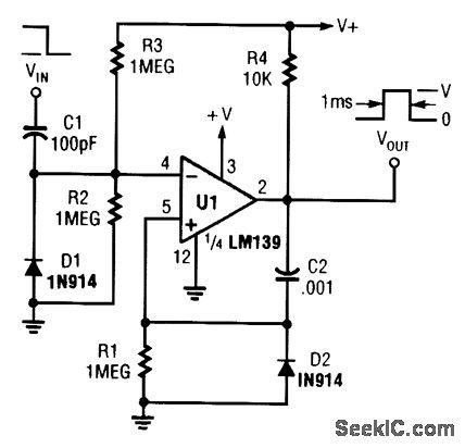
A section of a quad LM139 is used here as a one-shot pulse former. (View)
View full Circuit Diagram | Comments | Reading(0)
Metal detector 7
Published:2011/7/29 2:49:00 Author:Ecco | Keyword: Metal detector
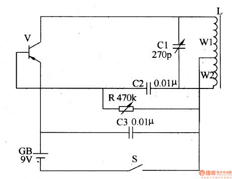
The working principle.The metal detector circuit uses LC single-tube oscillator circuit, it is shownas Figure 8-73.
In the circuit, V is oscillating tube, L is the detection coil, Cl is the resonant capacitor. After turning on power switch S, the LC single-tube oscillator circuit starts oscillation, semiconductor superheterodyne radio speaker will issue the sounds with the frequency in lkHz. When the search coil L detects underground metal, the radio frequency of the sound of the speaker becomes high. Component's selection R uses variable resistor (270P seal simply connected); C2 and C3 use high frequency ceramic capacitor or glaze capacitors. V selects 3AGl or 3AGIl High Frequency Low Power PNP germanium transistors. GB uses 9V laminated battery. L uses enameled wire with φO · 5lmm which is winded on the 5mmxlOmmx8Omm magnet bar with 80 turns (60 turns at the tap, W1 has 60 turns, W2 has 20 turns.) For increasing the sensitivity of L, it can also be winded the coil with the diameter in 3Ocm, the coil should be parallel to the ground. (View)
View full Circuit Diagram | Comments | Reading(3594)
Metal detector 8
Published:2011/7/29 2:41:00 Author:Ecco | Keyword: Metal detector
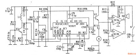
This example describes a metal detector which uses a PLL (phase locked loop) digital integrated circuit MCl4046, it can emit the alarm signal when detects metal objects, and it can determine detected material which is based on current meter's instructions. The device is suitable for detection of nails in wood, the metal objects in sand, wires in walls and so on.
The working principle.The metal detector circuit is composed of dection circuit, PLL phase-locked loop circuit and sound alarm circuit, it is shown in Figure 8-74.
Detectioncircuit is composed of the detection coil L, the transistor Vl, resistors Rl-R3, capacitors Cl-C5.
PLL phase-locked loop circuit consists of integrated circuit ICl, resistors R4-R8, capacitor C7-Cll.
Sound alarm circuitis composed ofthe transistor V2, comparing amplifier integrated circuit IC2, buzzer HA, resistors Rg-R14.
Rl-Rl4 use 1/4W carbon film resistors or metal film resistors; Rl5 uses 1/2W metal film resistors. RP uses small potentiometer or variable resistor. Cl, C2, C7-C9, Cl2 and C13 select monolithic capacitors; C3-C6 and ClO use high-frequency ceramic capacitors; C11 uses fine-tuning capacitor (semi variable capacitor). Vl and V2 use S9018 or 2SCl815 NPN silicon transistor. ICl uses MCl4046B PLL PLL CD4046 integrated circuit; IC2 uses PPC393C type operational amplifier integrated circuit. (View)
View full Circuit Diagram | Comments | Reading(11150)
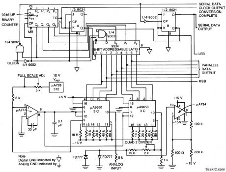
8_BIT_A_D_CONVERTER
Published:2009/6/24 1:33:00 Author:Jessie
View full Circuit Diagram | Comments | Reading(1338)
Resistance(RC)Coupling Voltage Amplifier Circuit
Published:2011/7/12 3:26:00 Author:Michel | Keyword: Resistance, Coupling Voltage, Amplifier Circuit
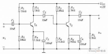
The above picture is a typical diode or triode resistance amplifier circuit.Because of C1,C2 stopping direct current effect and each level DC work condition is complete independent,thus they can be modulated indepently.But, for ac signal, all levels have close relationship,the former stage output voltage is the latter stage input signal and total voltage amplification times of two levels amplifiers are equal to all level amplifiers product,namely,u=Au1*Au2.Meanwhile, the latter level input impedance is the former stage load. (View)
View full Circuit Diagram | Comments | Reading(2330)
Auto counter for producivity 1
Published:2011/7/29 2:41:00 Author:Ecco | Keyword: Auto counter , producivity
The auto counter for productivity described in the example uses infrared control technology, the circuit is simple and easy to make, the effect of on-site use is better, it can be used for automatic counting of a variety of assembly line production.
The working principle.
The auto counter for productivity circuit is composed of infrared transmitter and infrared receiver count circuit.
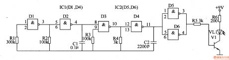
Infrared transmitter circuit is composed of a positive feedback modulation capacitor oscillator circuit, 4OkHz pulse oscillator and driver circuit, it is shown in Figure 8-80.
Positive feedback modulation capacitor oscillator circuit is composed of the NAND gate integrated circuit ICl (Dl-D4) internal Dl and D2 and resistors Rl and R2, capacitor Cl. 4OkHz pulse oscillator circuit is composed of the D3 and D4 inside of ICl and resistors R3 and R4, capacitor C2.
The drive circuit is composed of the IC and non-IC2 (D5, D6), resistors R5 and R6, transistor Vl and infrared light-emitting diode VLl.
Infrared receiver counting circuit is composed of the amplifier circuit, monostable trigger circuit A, B and counter, andit is shown in Figure 8-81.
The infrared receiver amplifier is composed of infrared receiver IC5, resistors R7 and R8 and the transistor V2.
A one-shot trigger circuit is composed of the time base IC lC3 and resistors R9 and Rll, capacitors C3-C5 and light-emitting diode VL2.
(View)
View full Circuit Diagram | Comments | Reading(793)
MULTIPLE_APERTURE_WINDOW_DISCRIMINATOR
Published:2009/6/23 5:07:00 Author:May

V1 through V4 are reference voltages that are derived from separate sources or from a com-mon voltage divider. (View)
View full Circuit Diagram | Comments | Reading(1)
| Pages:341/471 At 20341342343344345346347348349350351352353354355356357358359360Under 20 |
Circuit Categories
power supply circuit
Amplifier Circuit
Basic Circuit
LED and Light Circuit
Sensor Circuit
Signal Processing
Electrical Equipment Circuit
Control Circuit
Remote Control Circuit
A/D-D/A Converter Circuit
Audio Circuit
Measuring and Test Circuit
Communication Circuit
Computer-Related Circuit
555 Circuit
Automotive Circuit
Repairing Circuit