
Basic Circuit
Index 353
COAX_CABLE_DRIVER
Published:2009/6/18 4:56:00 Author:May
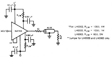
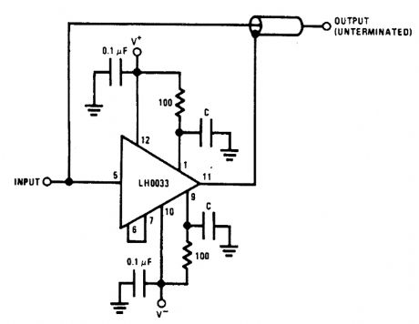
Becbuse of their high-current drive capability, the LH0002, LH0033, and LH0063 buffer ampli-fiers are suitable for driving terminated or unterminated coaxial cables, and high-current or reactive loads. Current-limiting resistors should be used to protect the device from excessive peak load cur-rents or accidental short circuit. No current limiting is built into the devices other than that imposed by the limited beta of the output transistors. This figure shows a coaxial-cable drive circuit. The 43-Ω resistor is included, the output voltage to the load is about half what it would be without the near-end termination. (View)
View full Circuit Diagram | Comments | Reading(1403)
VIDEO_CABLE_DRIVER
Published:2009/6/18 4:55:00 Author:May
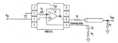
The driver's frequency response is tunable for a specific cable length via components connected to the summing node. By shunting R1,RC, acts to increase the amplifier's gain, and CC controls the cut-in frequency of the compensation.These three components peak the amplifier's frequency response to counteract the cable's roll-off characteristic. By squeezing more bandwidth out of a given cable, higher-performance cables aren't needed. (View)
View full Circuit Diagram | Comments | Reading(0)
LOW_DISTORTION_COMPOSITE±100_mA_LINE_DRIVER
Published:2009/6/18 4:54:00 Author:May
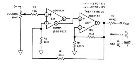
This line driver combines the high input impedance of an FET-input IC and a 100-mA op amp.U1's output is left open. The compensation terminal (pins) drive U2's high-Z input for increased overall phase margin. Gain is 14 dB, THD +N at 5 V, and RMS output is around 0.001% below 20 kHz. (View)
View full Circuit Diagram | Comments | Reading(1157)
TTL_BASED_SPEAKER_DRIVER
Published:2009/6/18 4:52:00 Author:May
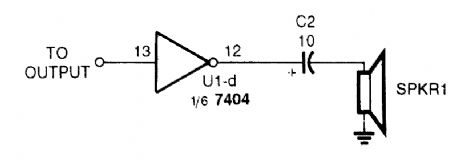
A TTL IC, such as a 7404, can drive a small speaker with enough audio to be used as an alarm or annunciator. The speaker can be a 32- or 100-Ω unit. (View)
View full Circuit Diagram | Comments | Reading(1077)
HIGH_SIDE_MOSFET_DRIVER
Published:2009/6/18 4:51:00 Author:May
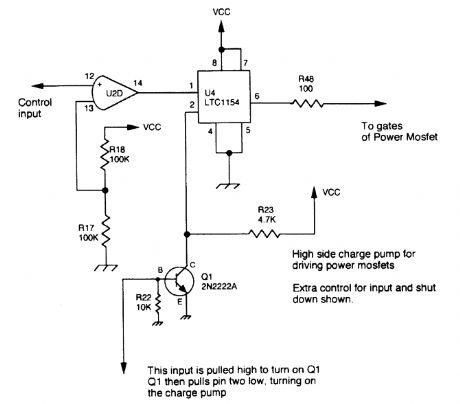
A Linear Technology LTC1154 is used as a charge pump to drive the gate of a high-side power MOSFET. (View)
View full Circuit Diagram | Comments | Reading(1388)
27125_MHz_NBFM_TRANSMITTER
Published:2009/6/18 4:44:00 Author:May
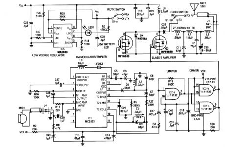
Using a Motorola MC2833 one-chip FM transmitter, a few support components, and an MPF6660 FET RF amp, this trans-mitter delivers about 3 W into a 50-Ω load. It is capable of operation over about 29 to 32 MHz with the components shown. (View)
View full Circuit Diagram | Comments | Reading(1547)
HIGH_SPEED_SHIELD_LINE_DRIVER
Published:2009/6/18 4:42:00 Author:May
View full Circuit Diagram | Comments | Reading(723)
STEREO_LINE_DRIVER
Published:2009/6/18 4:42:00 Author:May


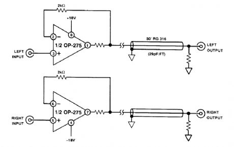
One Analog Devices OP-275 can be used for stereo line driver applications. (View)
View full Circuit Diagram | Comments | Reading(773)
IMPEDANCE_MATCHED_LINE_DRIVER_WIHH_75_Ω_LOAD
Published:2009/6/18 4:31:00 Author:May
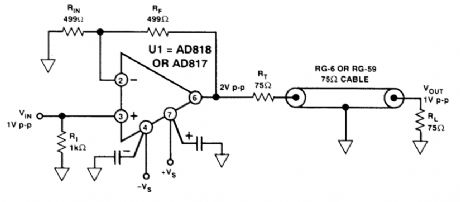
This circuit is a wideband 75-Ω line driver, for video applications (1 V p-p into 75Ω). (View)
View full Circuit Diagram | Comments | Reading(629)
TWO_INPUT_VIDEO_MUX_CABLE_DRIVER
Published:2009/6/18 4:29:00 Author:May

View full Circuit Diagram | Comments | Reading(662)
LOW_COST_ACCURATE_SQUARE_ROOT_CIRCUIT
Published:2009/6/18 4:21:00 Author:May
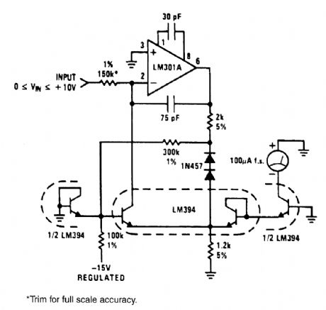

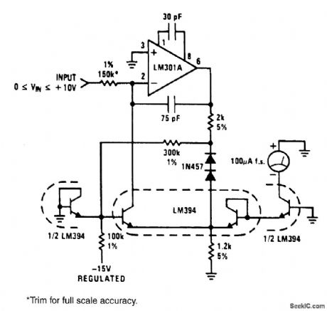
The circuit will generate a square-root function, accurately and inexpensiveJy. The output is a current that can be used to drive a meter directly or be converted to a voltage with a summing junc-tion current-to-voltage converter. The-15-V supply is used as a reference, so it must be stable. A 1% change in The-15-V supply will give a 1/2% shift in output reading. No positive supply is required when an LM301A is used because its inputs can be used at the same voltage as the positive supply (ground). The two 1N457 diodes and the 300-kΩ resistor are used to temperature-compensate the current through the diode-connected1/2 LM394. (View)
View full Circuit Diagram | Comments | Reading(1599)
MULTIPLEXED_BCD_DECODER_DRIVER_CIRCUIT
Published:2009/6/18 4:12:00 Author:May
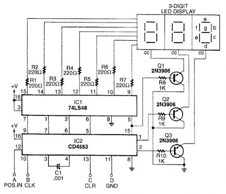
The BCD decoder-driver circuit will interface with any standard BCD output to produce a digital display. (View)
View full Circuit Diagram | Comments | Reading(2464)
LOW_COST_ONE_QUADRANT_MULTIPIER_DIVIDER
Published:2009/6/18 4:02:00 Author:May


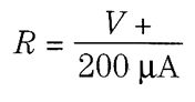
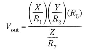
This circuit will produce an output that is proportional to the product of the (JQ and ()] inputs divided by the Z input. All inputs must be positive, limiting operation to one quadrant.For very low level inputs, the offset voltage in the LM308s might create large percentage errors referred to input. A simple scheme for offsetting any of the LM308s to zero is shown in dotted line; the positive input of the appropriate LM308 is simply tied toRX instead of ground for zeroing. The summing mode of operation on all inputs allows easy scaling on any or all inputs. Simply set the input resistor equal to (Vin(max)/200μA). Vout is equal to:Input voltages above the supply voltage are allowed because of the sumrning mode of operation. Several inputs can be summed at X,Y,and Z.For a simple {X)·(Y) or (X)/Z function, the unused input must be tied to the reference voltage. Perturbations in this reference will be seen at the output as scale factor changes, so a stable refer-ence is necessary for precision work. For less critical applications, the unused input can be tied to the positive supply, with (View)
View full Circuit Diagram | Comments | Reading(892)
TWO_TONE_ENCODER
Published:2009/6/18 3:49:00 Author:May
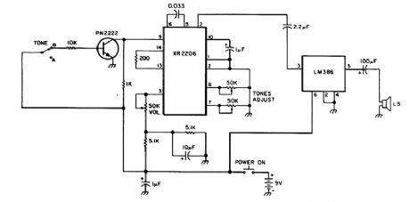
Using an XR2206 oscillator, this circuit can generate two audio tones. Switching between tones can be done with a logic level to either the base of the PN2222 or pin 9 of the XR2206. (View)
View full Circuit Diagram | Comments | Reading(0)
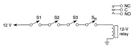
RELAY“OR”CIRCUIT
Published:2009/6/18 3:41:00 Author:May
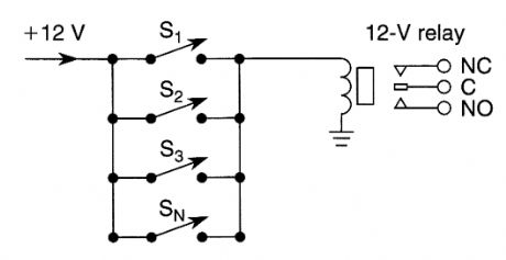
Closing any switch S1,S2,S3,or Sn will actuate the relay(N=any number).Use this circuit for burglar alarms,etc. (View)
View full Circuit Diagram | Comments | Reading(635)
RELAY“AND”CIRCUIT
Published:2009/6/18 3:37:00 Author:May
All switches 51 through Sn must be closed to operate the relay.If one opens,the relay drops out.Use this circuit for burglar alarms,etc. (View)
View full Circuit Diagram | Comments | Reading(642)
SIMPLE_IDENTIFIER
Published:2009/6/18 3:30:00 Author:May
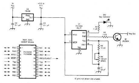
This identifier uses a PIC 16C54 microcontroller which must be programmed for your desired identifier. (View)
View full Circuit Diagram | Comments | Reading(1448)
AND_GATE
Published:2009/6/18 3:29:00 Author:May
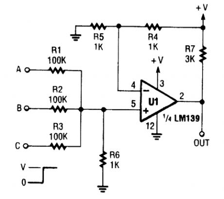
An LM1139 is configured as an AND gate(TTL or CMOS is usually used).use leftover IC sections and save an extra package in some instances. (View)
View full Circuit Diagram | Comments | Reading(0)
COMBINATORIAL_LOGIC_MULTIPLEXER
Published:2009/6/18 3:23:00 Author:May
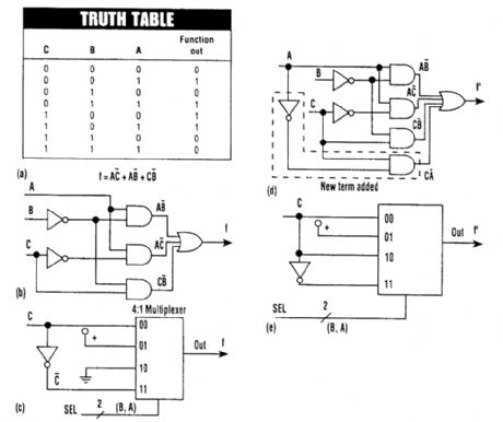
Combinatorial logic can be implemented simply by using a multiplexer instead of logic gates.Shown are the truth table(A), its logic circuit(B), and the multiplexer connections(C). If the logic circuitry is changed(D), the multiplexer would be reconnected(E). (View)
View full Circuit Diagram | Comments | Reading(1003)
PF_LINE_SAMPLER_COUPLER
Published:2009/6/18 3:02:00 Author:May
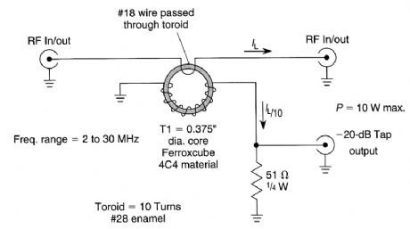
Suitable for RE line sampling, this coupler is useful where an indirect measurement of line cur-rent is needed. A 10:1 turn ratio yields a secondary current about1/10 (ideally) of the line current. A 51-Ω, resistor terminates the secondary. Insertion loss in the main line is negligible, < 0.l dB. For higher power levels, use proportionately larger core for T1. (View)
View full Circuit Diagram | Comments | Reading(740)
| Pages:353/471 At 20341342343344345346347348349350351352353354355356357358359360Under 20 |
Circuit Categories
power supply circuit
Amplifier Circuit
Basic Circuit
LED and Light Circuit
Sensor Circuit
Signal Processing
Electrical Equipment Circuit
Control Circuit
Remote Control Circuit
A/D-D/A Converter Circuit
Audio Circuit
Measuring and Test Circuit
Communication Circuit
Computer-Related Circuit
555 Circuit
Automotive Circuit
Repairing Circuit