
Basic Circuit
Index 355
VISIBLE_LIGHT_RECEIVER
Published:2009/6/17 1:41:00 Author:May
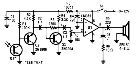
This receiver for amplitude-modulated light signals uses phototransistor Q1 mounted in a para-bolic reflector (to increase range). Any npn phototransistor should work. Emitter-follower Q2 drives amplifier Q3. The output from Q3 feeds volume control R7 and audio amplifier UI. A 9- to 12-V supply is recommended for the receiver. (View)
View full Circuit Diagram | Comments | Reading(1088)
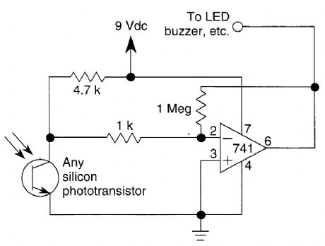
LIGHT_WAVE_VOICE_COMMUNICATION_RECEIVER
Published:2009/6/16 23:54:00 Author:May
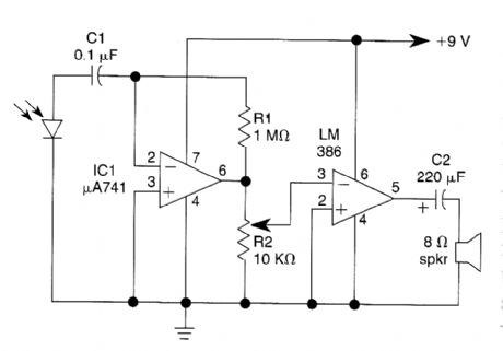
This light-wave receiver consists of a 741 op-erated as a preamplifier and an LM386 operated as a power amplifier. Potentiometer R2 is the gain control. Various kinds of detectors can be used as the front end of the receiver. Phototransistors are very sensitive, but they do not work well in the presence of too much ambient light. A 100-kQ se-ries resistor is required if you use a phototransis-tor. Solar cells, photodiodes, and LEDs of the same semiconductor as the transmitter all work well in this circuit. (View)
View full Circuit Diagram | Comments | Reading(990)
FM_LIGHT_BEAM_RECEIVER
Published:2009/6/16 23:51:00 Author:May
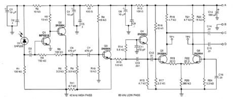
This receiver will pick up IR or light beams that are frequency modulated on a 50-kHz carrier Q2/Q1/Q3/Q4 from an active filter and amplifier and differential amp Q5/Q6 provide more gain. (View)
View full Circuit Diagram | Comments | Reading(813)
POWER_MOSFET_INVERTER
Published:2009/6/16 23:29:00 Author:May
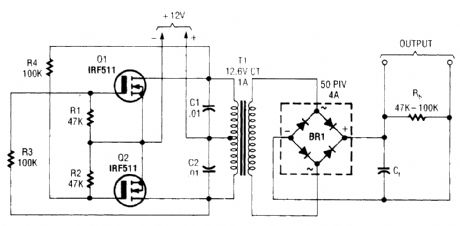
T1 is a suitable transformer for the voltage desired, with a 12.6-V CT winding. (View)
View full Circuit Diagram | Comments | Reading(1)
dc_to_ac_INVERTER
Published:2009/6/16 23:28:00 Author:May
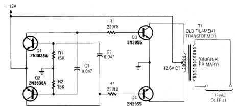
A multivibrator circuit drives a pair of 2N3055 power transistors transformer with a 120-V primary. (View)
View full Circuit Diagram | Comments | Reading(5824)
DIGITAL_INVERTER
Published:2009/6/16 23:27:00 Author:May
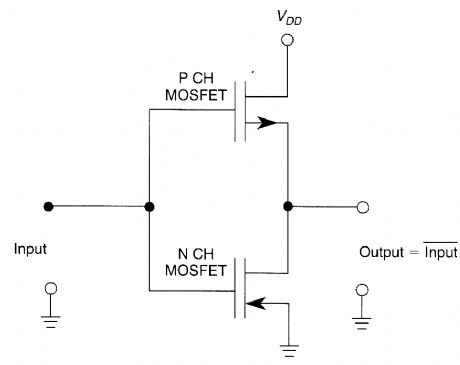
A CMOS digital inverter is formed by con-necting two MOSFETS, as shown. (View)
View full Circuit Diagram | Comments | Reading(863)
ONE_WAY_VOICE_ACTIVATED_INTERCOM
Published:2009/6/16 22:57:00 Author:May
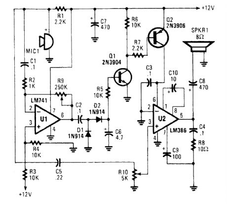
An omnidirectional electret microphone can be used to pick up the sound and convert it into an electrical signal. The output of the microphone is fed along two paths. In the first path, the signal is sent to the inverting input at pin 6. In the second path, the microphone signal is fed to the non-in-verting input of U2, where it is amplified and output to the speaker, SPKR1. (View)
View full Circuit Diagram | Comments | Reading(1341)
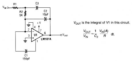
FAST_INTEGRATOR
Published:2009/6/16 22:54:00 Author:May
View full Circuit Diagram | Comments | Reading(1)
IR_RECEIVER
Published:2009/6/16 22:26:00 Author:May
This circuitis just about the simplest IR ro-celver you can build The parts are cheap,the lay-outis not critical,and a 9-V battery will last a longtime (View)
View full Circuit Diagram | Comments | Reading(3)
WIRELESS_IR_HEADPHONE_RECEIVER
Published:2009/6/16 22:18:00 Author:May
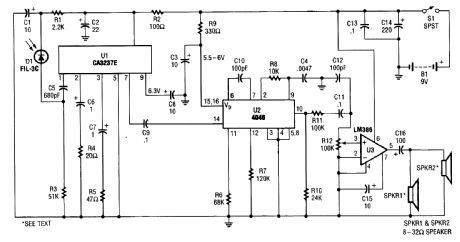
IR detector diode D1 intercepts the IR signal at around 40 kHz and feeds it from U1, a high-gain preamp, to PLL, U2, a 4046 configured to serve as an FM detector. U3 is an audio amplifier that feeds a pair of headphones or a speaker. (View)
View full Circuit Diagram | Comments | Reading(0)
WIRELESS_IR_HEADPHONE_TRANSMITTER
Published:2009/6/16 22:17:00 Author:May
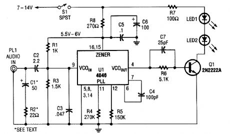


The transmitter for the wireless headphones is built around a CD4046 CMOS phase-locked loop, coupled with a driver transistor, and a pair of infrared LEDs. Although the CD4046 is comprised of two phase comparators, a voltage-controlled oscillator (or VCO), a source follower, and a zener ref-erence, only its VC0 is used in this application. (View)
View full Circuit Diagram | Comments | Reading(0)
INFRARED_RECEIVER
Published:2009/6/16 22:14:00 Author:May
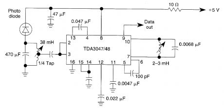
The circuit operates from a 5-V supply and has a current consumption of 2 mA. The output is a current source that drives or suppresses a current of more than 75 pA with a voltage swing of 4.5 V.The Q-killer circuit eliminates distortion of the output pulses because of the decay of the tuned in-put circuit at high input voltages. The input circuit is protected against signals of more than 600 mV by an input limiter. The typical input is an AM signal at a frequency of 36 kHz. (View)
View full Circuit Diagram | Comments | Reading(0)
AND_GATE
Published:2009/6/16 21:46:00 Author:May
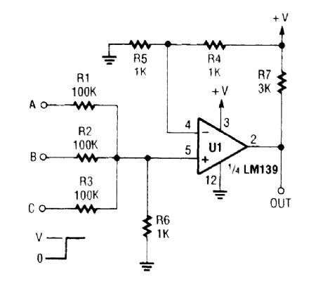
A left-over section of a quad op amp can be used to save cost and eliminate an extra logic chip for this AND gate. (View)
View full Circuit Diagram | Comments | Reading(0)
1_kHz_TONE_FILTER
Published:2009/6/16 21:29:00 Author:May
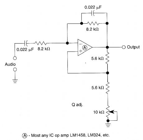


The Wien-bridge based filter has a variable bandwidth and a center frequency of 900 Hz. The circuit will oscillate if the 10-kΩ pot is set too low. (View)
View full Circuit Diagram | Comments | Reading(800)
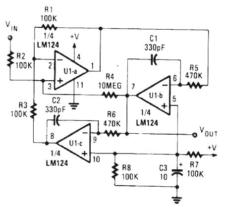
FULL_WAVE_RECTIFIER_AVERAGING_FILTER
Published:2009/6/16 21:27:00 Author:May
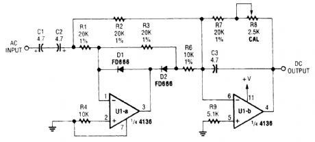
The input signal is rectified by D1 and D2 Op amp U1-a,and fed to output amp U2 R8 is set for correct circuit calibration. (View)
View full Circuit Diagram | Comments | Reading(773)
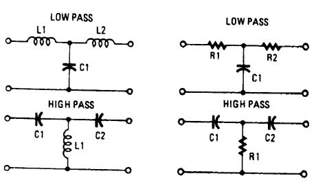
PASSIVE_T_FILTER_CONFIGURATIONS
Published:2009/6/16 21:19:00 Author:May
View full Circuit Diagram | Comments | Reading(819)
BI_QUAD_RC_BANDPASS_FILTER
Published:2009/6/16 21:19:00 Author:May
View full Circuit Diagram | Comments | Reading(705)
AUDIO_RANGE_FILTER
Published:2009/6/16 21:18:00 Author:May
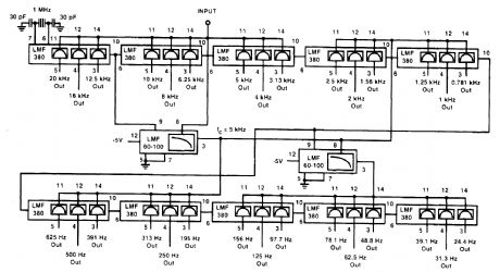
The LMF380 switched audio filter by National Semiconductor is used here to obtain a third-oc-tave filter set that covers the entire audio range. (View)
View full Circuit Diagram | Comments | Reading(780)
455_kHz_NARROW_BAND_IF_FILTER
Published:2009/6/16 21:14:00 Author:May
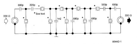
This filter uses five 455-kHz ceramic resonators. The impedance is 330Ω, the bandwidth is 800 Hz, and the ultimate rejection ≥60dB. The ceramic resonators could be replaced by crystals. (View)
View full Circuit Diagram | Comments | Reading(3311)
CURRENT_DRIVEN_SALLEN_KEY_FILTER
Published:2009/6/16 21:13:00 Author:May
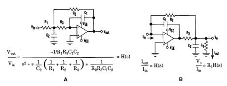
The low-pass Sallen-Key filter is staple for designers because it contains few components (A).By redesigning the filter, a current to voltage conversion can be avoided when the input signal to be filtered is in current form (B). (View)
View full Circuit Diagram | Comments | Reading(754)
| Pages:355/471 At 20341342343344345346347348349350351352353354355356357358359360Under 20 |
Circuit Categories
power supply circuit
Amplifier Circuit
Basic Circuit
LED and Light Circuit
Sensor Circuit
Signal Processing
Electrical Equipment Circuit
Control Circuit
Remote Control Circuit
A/D-D/A Converter Circuit
Audio Circuit
Measuring and Test Circuit
Communication Circuit
Computer-Related Circuit
555 Circuit
Automotive Circuit
Repairing Circuit