
Protection Circuit
Index 11
Motor protector 10
Published:2011/4/27 20:49:00 Author:Ecco | Keyword: Motor protector
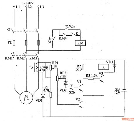
The motor protector described in the example can cut off the power supply when any phase of power in three-phase AC motor being lacking, it can prevent winding overheating damage due to broken phase operation.
The working principle
The motor protector circuit is composed of the voltage detection circuit and protection controlling execution circuit, it is shown as Figure 8-46.
Starting control circuit is composed of stopping button Sl, starting button S2 and AC contactor KM (the original motor starting circuit).
Voltage detection circuit is composed of the diodes VDl-VD3, Zener diode VSl-VS3, resistors Rl-R6, capacitors Cl-C3 and optocouplers VLCl-VLC3.
Protection control circuit consists of transistors V, relay K, the diode VD4 and resistor R7.
Rl, R3 and R5 use 1-2W metal film resistors; R8, R4, R6 and R7 use 1/4W carbon film resistors or metal film resistors.
Cl-C3 select aluminum electrolytic capacitors with voltage in 16V.
VDl-VD4 use 1N4007 silicon rectifier diodes.
VSl-VS3 select lW, 9 · IV silicon voltage regulator diodes.
V uses S8050, 3DG805O, BC136 or other models NPN silicon transistors.
VLCl-VLC3 use 4N25 or MCT2E, TL206 coupler.
K uses 9V DC relay. (View)
View full Circuit Diagram | Comments | Reading(2074)
The fridge over voltage, under voltage, power delay protector composed of 556
Published:2011/4/19 3:08:00 Author:Ecco | Keyword: fridge, over voltage, under voltage, power delay , protector
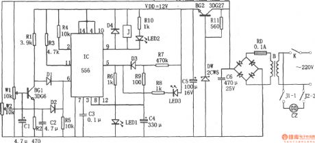
The chart shows a fridge over voltage, under voltage, power delay protector circuit. The circuit consists of over and under voltage sampling circuit, trigger circuit, delay circuit, the buck rectifier circuit. And the buck rectifier circuit provides DC voltage for the entire circuit.
(View)
View full Circuit Diagram | Comments | Reading(3631)
The internal structure of HL601A
Published:2011/4/14 6:29:00 Author:may | Keyword: internal structure
HL601A is thick film integrated circuit.It can achieve dual-level protection of signal's over current, over voltage, over heating, etc. Its features include precise threshold, fast speed, and high reliability. (View)
View full Circuit Diagram | Comments | Reading(612)
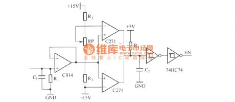
Three phases of phase lack protection circuit
Published:2011/3/27 22:45:00 Author:Jessie | Keyword: Three phases, phase lack protection
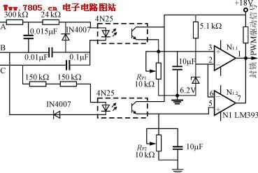
This is a kind of protection circuit used for three-phase three-wirepower phase lack, A, B and C lack any phase, light-coupler output level is lower than comparator's reversed-phase input terminal's benchmark voltage, comparator output low level, blockade PWM drive signal, andcut offpower. Comparator input polarity fluctuant, also can use a high level blockade PWM signal. This phase lack protection circuit uses high light-coupler isolation, safe and reliable, RP2, RP1 used to adjust phase lack protection movement threshold.
(View)
View full Circuit Diagram | Comments | Reading(2408)
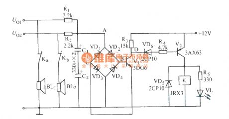
Bridge type picked up horn protection circuit (2)
Published:2011/3/23 3:56:00 Author:Jessie | Keyword: horn protection
View full Circuit Diagram | Comments | Reading(616)
The principle diagram of IGBT over current protection circuit
Published:2011/4/10 21:50:00 Author:may | Keyword: IGBT, over current protection
View full Circuit Diagram | Comments | Reading(1423)
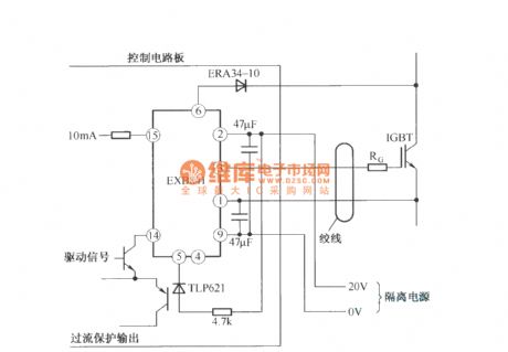
The application circuit of EXB841
Published:2011/4/10 21:28:00 Author:may | Keyword: application
View full Circuit Diagram | Comments | Reading(1061)
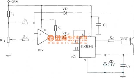
The principle circuit of EXB841
Published:2011/4/10 21:30:00 Author:may
View full Circuit Diagram | Comments | Reading(1877)
The application circuit of EXB850
Published:2011/4/10 21:31:00 Author:may
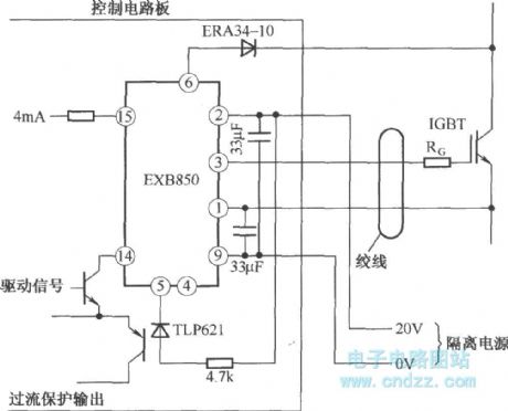
View full Circuit Diagram | Comments | Reading(772)
The battery voltage protection indicating circuit diagram
Published:2011/4/7 22:14:00 Author:Ecco | Keyword: battery voltage, protection indicating
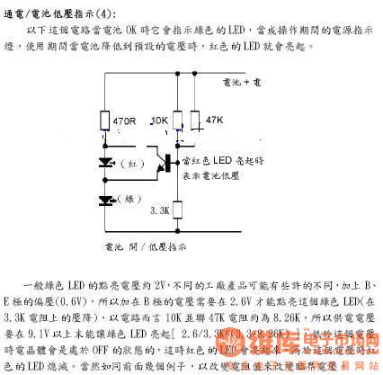
Power, low battery indication
In the following circuit when the battery is OK, it indicates the green LED, the LED is the power indicator during operation. When the battery voltage is lower than the default, the red LED light will light up.
(View)
View full Circuit Diagram | Comments | Reading(996)
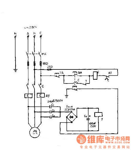
A power-saving three-phase asynchronous motor-phase protection device
Published:2011/4/6 1:04:00 Author:Ecco | Keyword: power-saving , three-phase asynchronous , motor-phase , protection device
View full Circuit Diagram | Comments | Reading(2020)
The application of IGBT in CO2 gas shielded welding power supply
Published:2011/4/8 1:38:00 Author:may | Keyword: IGBT, CO2 gas, shielded welding, power supply
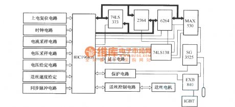
1, In order to accurate control the process of short circuit, main circuit adopts IGBT with very high working frequency as switch power device. The main circuit of CO2 gas shielded welding power supply adopts full bridge structure.
2, 80C196KB control system structure principle block diagram
(View)
View full Circuit Diagram | Comments | Reading(1780)
Over voltage buffer protection circuit in the process of IGBT switching
Published:2011/4/8 1:23:00 Author:may | Keyword: Over voltage, buffer protection, IGBT switching
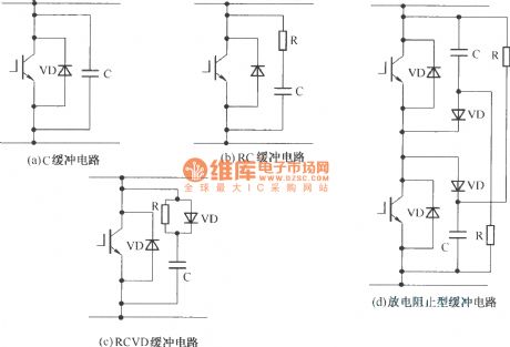
(a) C buffer circuit
(b) RC buffer circuit
(c) RCVD buffer circuit
(d) Discharge blocking buffer circuit (View)
View full Circuit Diagram | Comments | Reading(2691)
IGBT concentrate over current protection principle diagram
Published:2011/4/8 1:16:00 Author:may | Keyword: IGBT, concentrate, over current protection
View full Circuit Diagram | Comments | Reading(861)
IGBT scattering overcurrent protection principle diagram
Published:2011/4/8 0:51:00 Author:may | Keyword: scattering overcurrent protection
View full Circuit Diagram | Comments | Reading(932)
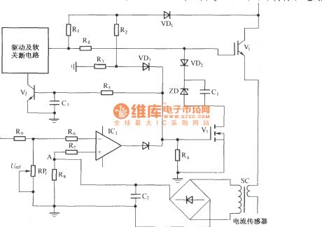
Integrated protection circuit with UCE increasing in IGBT short cut and current sensor detection
Published:2011/4/2 3:38:00 Author:may | Keyword: Integrated protection, UCE enlarging, IGBT short cut, current sensor detection
View full Circuit Diagram | Comments | Reading(1314)
Protection circuit using the principle of UCE increasing in IGBT overcurrent
Published:2011/4/6 3:50:00 Author:may | Keyword: Protection, UCE increasing, IGBT overcurrent
View full Circuit Diagram | Comments | Reading(1237)
IPM peripheral protection circuit
Published:2011/4/7 3:40:00 Author:may | Keyword: IPM, peripheral protection
View full Circuit Diagram | Comments | Reading(628)
IPM defencive function block diagram
Published:2011/4/7 20:03:00 Author:may | Keyword: defencive function
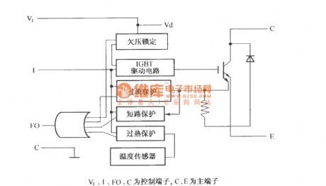
V1, I, f0, C is control terminal, C, E is main terminal (View)
View full Circuit Diagram | Comments | Reading(846)
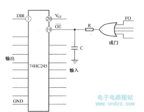
Short-circuit protection function test method 2 of IGBT drive circuit
Published:2011/4/7 5:07:00 Author:may | Keyword: IGBT drive, Short-circuit protection function, test method
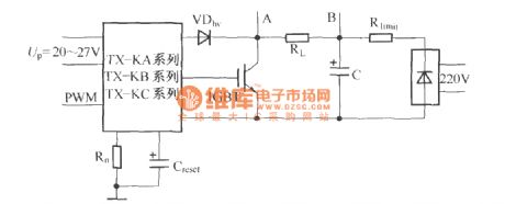
Rlimit =10~100Ω,C=10~470μF,Creset=10nF. (View)
View full Circuit Diagram | Comments | Reading(782)
| Pages:11/12 123456789101112 |
Circuit Categories
power supply circuit
Amplifier Circuit
Basic Circuit
LED and Light Circuit
Sensor Circuit
Signal Processing
Electrical Equipment Circuit
Control Circuit
Remote Control Circuit
A/D-D/A Converter Circuit
Audio Circuit
Measuring and Test Circuit
Communication Circuit
Computer-Related Circuit
555 Circuit
Automotive Circuit
Repairing Circuit