
Protection Circuit
Index 7
wireless remote control dimmable lamp(1)
Published:2011/7/19 23:43:00 Author:chopper | Keyword: wireless, remote control, dimmable lamp
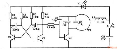
Decorative lights like general droplights are not of remote control and dimming functions,and they are very uneasy to use. This example describes the wireless remote control dimmable droplight, which is with power on/off and multi-level dimming functions,and the control distance is about 20m. The principle of circuitThe wireless remote control dimmable droplight circuit is formed by the wireless remote control transmitter circuit and wireless receiver dimmable controller circuit. Wireless remote control transmitter circuit is formed by the astable multivibrator,high-frequency oscillator,which is shown in Figure 1-197
(View)
View full Circuit Diagram | Comments | Reading(1317)
agricultural non-tower pressure-charged water feeder(2)
Published:2011/7/19 23:41:00 Author:chopper | Keyword: agricultural, non-tower, pressure-charged, water feeder
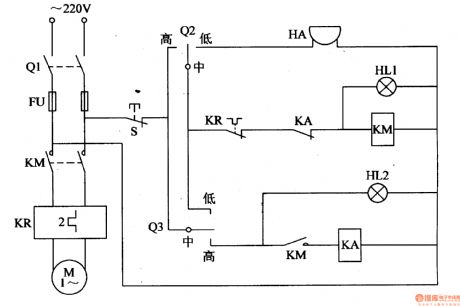
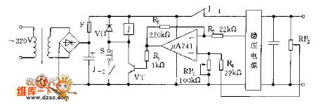
This example describes the agricultural non-tower pressure-charged water feeder,and it uses electric connecting pressure gauge as the measurement and control device.The circuit is simple, and it can cut off the power supply automatically when the water supply is not enough or the submersible pump fails to work,while the alarm sends a sound. The principle of circuit This agricultural non-tower pressure-charged water feeder circuit is formed by the knife switch Q1,fuse FU,intermediate relay KA,AC contactor KM, thermal relay KR,alarm HA, lights HL1,HL2 and the control contact of pump outlet pressure gauge Q2,control contact of tank water level testing gauge Q3, which is shown in figure 4-153.
(View)
View full Circuit Diagram | Comments | Reading(600)
greenhouse ground hotline controller(1)
Published:2011/7/19 23:40:00 Author:chopper | Keyword: greenhouse, ground hotline, controller
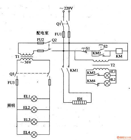
In the northern winter and spring, farmers usually lays the ground hotline to assist warming in order to increase the temperature inside the greenhouse,and promote the growth of seedlings,vegetables.Here is a ground hotline controller of common-used single-phase power for installation reference. The principle of circuitThis greenhouse ground hotline controller circuit is formed by the control circuit,working status indication circuit and low voltage lighting circuit, which is shown in figure 4-198.
(View)
View full Circuit Diagram | Comments | Reading(598)
greenhouse ground hotline controller(2)
Published:2011/7/19 23:38:00 Author:chopper | Keyword: greenhouse, ground hotline, controller
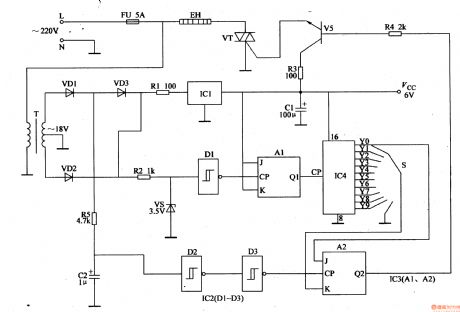
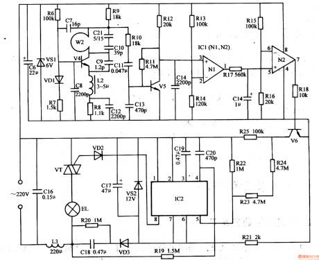
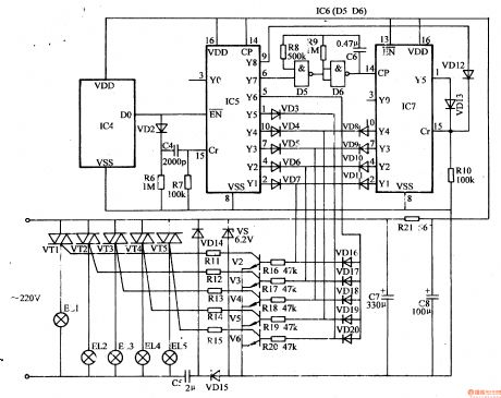
This example describes the greenhouse ground hotline controller, which uses the cycle rate control,and it is of advantages like energy saving, small harmonic interference and so on. The principle of circuitThe greenhouse ground hotline controller circuit is formed by power supply circuit and heating control circuit, which is shown in figure 4-199. Power supply circuit is formed by the fuse FU,power transformer T,rectifier diodes VD1-VD3, resistor R1,three-terminal voltage regulator integrated circuit IC1 and filter capacitor C1. Heating control circuit consists of resistors R2-R5,capacitor C2,voltage regulator diode VS,non-gate Schmitt trigger integrated circuit IC2 (D1-D3), trigger JK integrated circuit IC3 (A1,A2,counting/pulse distribution integrated circuit IC4, selective switch S,the transistor V,thyristor VT and ground hotline EH.
(View)
View full Circuit Diagram | Comments | Reading(1016)
Over-Voltage And Over-Current Protection Circuit Which Meets Any Stabilized Voltage Supply
Published:2011/7/18 9:32:00 Author:Robert | Keyword: Over-Voltage, Over-Current, Protection, Stabilized Voltage Supply
The picture shows the over-voltage and over-current protection circuit which meets any stabilized voltage supply. (View)
View full Circuit Diagram | Comments | Reading(701)
Protection Circuit of Transistor Regulating Power Supply
Published:2011/7/17 7:16:00 Author:Michel | Keyword: Regulating Power Supply, Protection Circuit
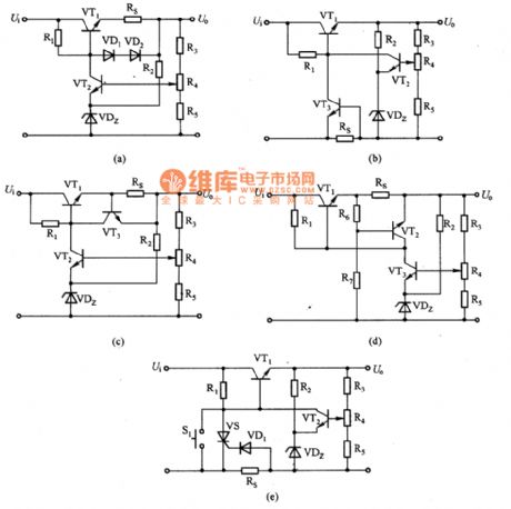
a、b、c、d、e are protection circuits of transistor regulating power supply.The voltage stabilizer load protection circuit has current limiting type and current cut-off type. In the picture,(a)~(d) are current limiting protection circuit.In the picture 1,VT1 base of electricity flows through VT1 VD1 and VD2 circulation when the voltage drop is more than VD1 Rs and VD2 positive voltage.Therefore, its emitter current is restricted and it uses the sharp increasing characteristics of diode forward voltage current.In figure (b) and (c),transistor UEB which has the same characteristics as diode,the VT3 UBE is controlled by testing voltage drop on RS to limit the VT1 emitter current and the limited current I. = 0.6 V/Rs.
(View)
View full Circuit Diagram | Comments | Reading(862)
eyes care lamp(2)
Published:2011/7/17 20:36:00 Author:chopper | Keyword: care lamp
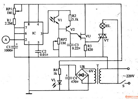
This example describes the eyes care lamp with functions like touch-sensitive light and turn off timing,and it can dim the light level according to the intensity of indoor light level automatically. The principle of circuitThe eyes care lamp circuit is formed by the power circuit, touch/timing control circuit and metering and dimming circuit,which is shown in Figure 1-19 The power circuit is formed by the power switch S,the power transformer T,bridge rectifier UR,filter capacitor C4,current limiting resistor R4 and the power indicative light-emitting diode VL.
(View)
View full Circuit Diagram | Comments | Reading(690)
eyes care lamp(1)
Published:2011/7/17 20:16:00 Author:chopper | Keyword: care lamp
This example describes the eyes care lamp, which has functions like automatic metering and manual dimming.when light is dim, the red LED lights, indicating that the light is not suitable for reading and writing, and it should increase the light level; and when the light is bright,the green LED lights to indicate that the area under the lamp is suitable for reading and writing. The principle of circuitThe eyes care lamp circuit is formed by the light metering/light intensity indication circuit and the light dimming circuit,which is shown in Figure 1-190.
(View)
View full Circuit Diagram | Comments | Reading(641)
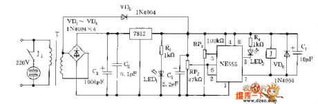
infrared remote control dimmable lamp
Published:2011/7/15 20:18:00 Author:chopper | Keyword: infrared, dimmable lamp
This example describes the infrared remote control dimmable lamp, which can use infrared remote controller of household appliances(such as televisions,DVD players,VCRs, etc.) to control,and it can open, turn off the light and dim(strong, medium, Weak 3 files) easily. The principle of circuit The infrared remote control dimmable lamp circuit is formed by the power supply circuit, infrared receiver amplification and dimming control circuit, which is shown in figure 1-201.
The power supply circuit is formed by the capacitor C4,discharge resistor Rll,rectifier diodes VD1,VD2,filter capacitor C3 and voltage-regulator diode VS.
(View)
View full Circuit Diagram | Comments | Reading(921)
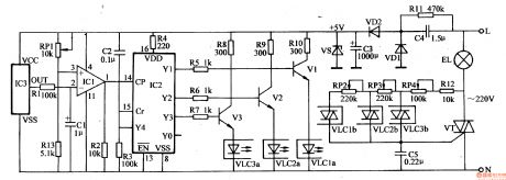
wireless remote control dimmable lamp(2)
Published:2011/7/17 20:50:00 Author:chopper | Keyword: dimmable lamp, remote control
This example describes the wireless remote control dimmable droplight,which can control the working state of droplightat will.It not only cancontrol a certain lamp (or all lamps) to turn on or turn off, but also can make the various incandescent lamps in the droplight lighted in order circularly to produce the effect like water light . The principle of circuitThe wireless remote control dimmable droplight circuit is formed by the wireless remote control transmitter circuit and wireless remote control receiver circuit. Wireless remote control transmitter circuit is formed by the pulse encoder circuit and wireless transmitter circuit,which is shown in Figure 1-199
(View)
View full Circuit Diagram | Comments | Reading(616)
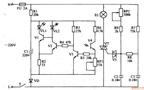
eyes care lamp(3)
Published:2011/7/17 20:36:00 Author:chopper | Keyword: care lamp
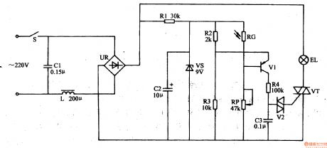
This example describes the eyes care lamp,which can dim the light level based on the intensity of indoor light level automatically. And it can protect the eyes and it is suitable for reading and writing. The principle of circuitThe eyes care lamp circuit is formed by the power circuit and optical control circuit,which is shown in Figure 1-192. Power supply circuit is formed by the power switch S, filter capacitors C1,C2,inductor L,bridge rectifier UR, current limiting resistor R1 and diode voltage regulator VS. The optical control circuit is formed by the photosensitive resistor RC, resistors R2-R4, potentiometer RP, capacitor C3, transistor V1,and dual-track trigger diode V2 and thyristor VT.
(View)
View full Circuit Diagram | Comments | Reading(659)
Two-phase servo drive circuit
Published:2011/7/12 10:22:00 Author:John | Keyword: Two-phase servo drive
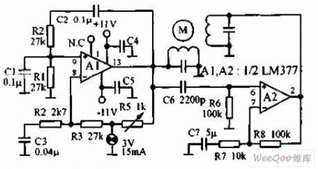
Two-phase servo drive circuit is as shown, which utilizes two components of an integrated power amplifier LM377. These two components, respectively, produce power of 3W to drive small 60Hz two-phase servo motor. The motor winding is of 8Ω, which is tuned to 60Hz with the shunt capacitor. The light bulb is used in steady ring circuit.
(View)
View full Circuit Diagram | Comments | Reading(713)
Over-Voltage Adjustable Protection Circuit
Published:2011/7/16 9:41:00 Author:Robert | Keyword: Over-Voltage, Adjustable, Protection

The picture shows the over-voltage adjustable circuit. (View)
View full Circuit Diagram | Comments | Reading(615)
Simple And Reliable Commercial Power Over-Voltage Protector Circuit
Published:2011/7/17 8:07:00 Author:Robert | Keyword: Simple, Reliable, Commercial Power, Over-Voltage, Protector
The picture shows the simple and reliable commercial power over-voltage protector circuit. (View)
View full Circuit Diagram | Comments | Reading(675)
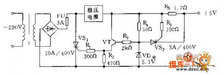
Stabilized Voltage Supply Adding Additional Over-Voltage Protection Circuit
Published:2011/7/17 8:10:00 Author:Robert | Keyword: Stabilized Voltage Supply, Over-Voltage, Protection
The picture shows the stabilized voltage supply adding additional over-voltage protection circuit. (View)
View full Circuit Diagram | Comments | Reading(555)
Over-Voltage Protection Circuit By Using The Principle Of Over-Heat Generated By Over-Voltage
Published:2011/7/17 8:04:00 Author:Robert | Keyword: Over-Voltage, Protection, Principle, Over-Heat
The pictrue shows the over-voltage protection circuit by using the principle of over-heat generated by over-voltage. (View)
View full Circuit Diagram | Comments | Reading(611)
Over-Voltage Protection Circuit Composed Of Fuse And Thyristor
Published:2011/7/17 9:42:00 Author:Robert | Keyword: Over-Voltage, Protection, Fuse, Thyristor
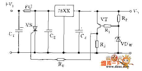
The picture shows the over-voltage protection circuit composed of fuse and thyristor. (View)
View full Circuit Diagram | Comments | Reading(793)
Over-Voltage Protection Circuit Composed Of Transistors
Published:2011/7/16 9:47:00 Author:Robert | Keyword: Over-Voltage, Protection, Transistor
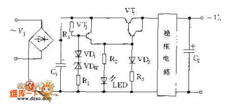
The picture shows the over-voltage protection circuit composed of transistors. (View)
View full Circuit Diagram | Comments | Reading(671)
Over-Voltage Protection Circuit Composed Of Transistor And Relay (2)
Published:2011/7/16 9:55:00 Author:Robert | Keyword: Over-Voltage, Protection, Transistor, Relay

The picture shows the over-voltage protection circuit composed of transistor and relay (2). (View)
View full Circuit Diagram | Comments | Reading(645)
Over-Voltage Protection Circuit Composed Of Transistor And Relay (1)
Published:2011/7/16 9:52:00 Author:Robert | Keyword: Over-Voltage, Protection, Transistor, Relay
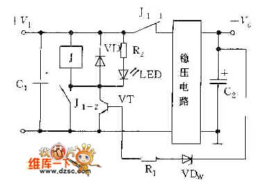
The picture shows the over-voltage protection circuit composed of transistor and relay (1). (View)
View full Circuit Diagram | Comments | Reading(673)
| Pages:7/12 123456789101112 |
Circuit Categories
power supply circuit
Amplifier Circuit
Basic Circuit
LED and Light Circuit
Sensor Circuit
Signal Processing
Electrical Equipment Circuit
Control Circuit
Remote Control Circuit
A/D-D/A Converter Circuit
Audio Circuit
Measuring and Test Circuit
Communication Circuit
Computer-Related Circuit
555 Circuit
Automotive Circuit
Repairing Circuit