
Protection Circuit
Index 4
CAMCORDER_BATTERY_PROTECTOR
Published:2009/7/14 2:27:00 Author:May
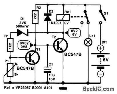
Many camcorder enthusiasts use their spare battery for powering video lights. Many such lights give no indication when the battery has gone flat. This can be avoided by the use of this protection circuit. When it gets switched on, the potential across C1 is zero, so that T2 is cut off, the relay is inactive, and the indicator lamp lights. As long as the battery voltage remains above a certain level, T1 is on and holds the base of T2 at earth potential. In this state, only a small current is drawn. When the battery voltage is no longer higher than the sum of the zener voltage, the potential set by divider R2-P1, and the drop across the base-emitter junction of T1, this transistor is cut off, whereupon C 1 is charged via R2. When the potential across C1 has risen to a value high enough for T2 to be switched on, the relay is energized, and its contact disconnects the lamp from the battery. Because the current drain (≤70 rnA) is then determined almost entirely by the relay, it is essential to remove, or disconnect, the battery from the light unit. The switch-off voltage level, set with P1, should be about 1 V per battery cell. (View)
View full Circuit Diagram | Comments | Reading(844)
Steam iron automatic protection circuit diagram
Published:2011/8/4 5:08:00 Author:Rebekka | Keyword: Steam iron, automatic protection
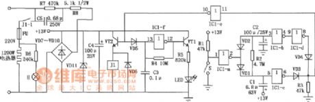
The circuit is shown as above, the commercial power passes C5, R7, R8 buck, VD7 ~ VDl0 commutating and VD11 regulator. The circuit provides operating voltage. When the iron is put horizontally, the mercury switch S downward about 15o and in a disconnected state. At this time, IC1-a outputs low level, C1 is charged by R2, ICl-c outputs low level, ICl-d has outputs low, VD3, VD4, IC1-e form NAND gate output high level, VT2 is turned on, relay Jl pulls in, then heating wire is heating, H neon lights are lit. (View)
View full Circuit Diagram | Comments | Reading(3680)
OVERCURRENT_PROTECTION_FOR_400_V_SUPPLY
Published:2009/7/13 2:46:00 Author:May
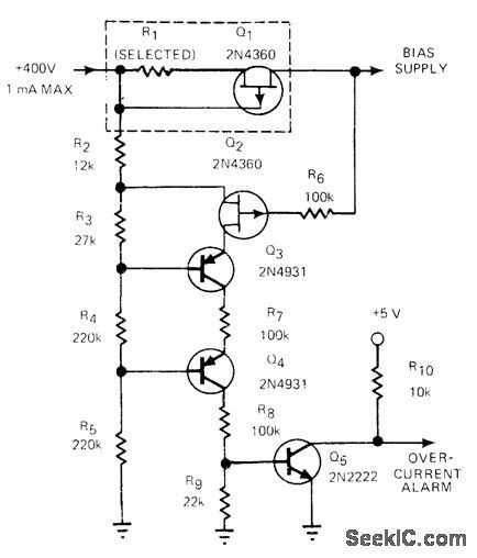
R1 and Q1 form current detector for bias supply. At normal current levels, voltage drop is very small and Q2 is reverse-biased. When current reaches 400 μA, voltage drop across R1 forces gate of Q1 to near pinchoff. Combined voltage drop across R1 and Q1 then becomes large so Q2 is forced almost to full conduction.Q3 and Q4 then tum on Q5, to provide overcurrent-alarm signal foractivating logic circuit that shuts off power supply.-J. P. Thompson, Overcurrent Alarm Protects HV Supply, EDN Magazine, Nov. 20, 1978, p 321-322. (View)
View full Circuit Diagram | Comments | Reading(1111)
Anti-electromagnetic Interference PWM Fan Controller Circuit
Published:2011/8/4 2:39:00 Author:May | Keyword: Anti-electromagnetic Interference, PWM Fan Controller
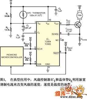
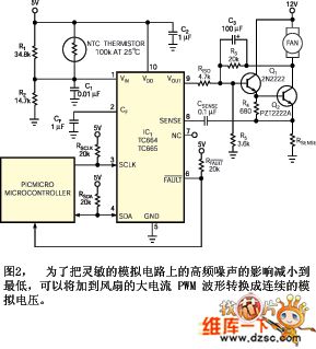
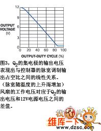
Microchip Tech-nology ( Microchip) company provides a type of fan refrigeration speed control system series product working on PWM mode, they are used for DC brushless cooling fans ( literature cite one) . We can use outside NTC(negative temperature coefficient) thermistor or a kind of PIC microcontroller from Microchip Tech-nology and SMBus serial data bus to utilize PWM waveform's dutyfactor to control fan speed.Figure 1 shows one kind of typical application ( literature cite two) description of TC664 and TC665 controller data information. It uses 1mF frequency control capacitor CF and fan controller IC1 to generatre a PWM pulse series, its nominal frequency is 30Hz,and thedutyfactor change range rely on temperatureis 30%-100%.
(View)
View full Circuit Diagram | Comments | Reading(2024)
SHUTDOWN_PROTECTION
Published:2009/7/13 1:52:00 Author:May
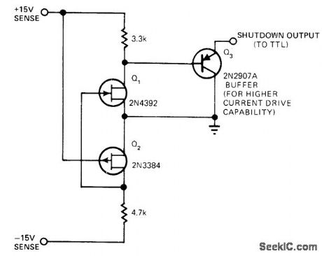
Used with digital logic to prevent generation of false logic signals when power supply is turned on or turned off, FETs sense +15 V and -15 V supplies and conduct when either supply drops below pinchoff voltage, activating shutdown output. With values shown, shutdown output is disabled when supplies exceed about 4 V, to provide normal operation.-E. Burwen, Power-Supply Monitor Suppresses False Output Signals, EDN Magazine, Nov. 5, 1977, p 110 and 112. (View)
View full Circuit Diagram | Comments | Reading(890)
SCR_OVERVOLTAGE_PROTECTOR
Published:2009/7/10 20:37:00 Author:May
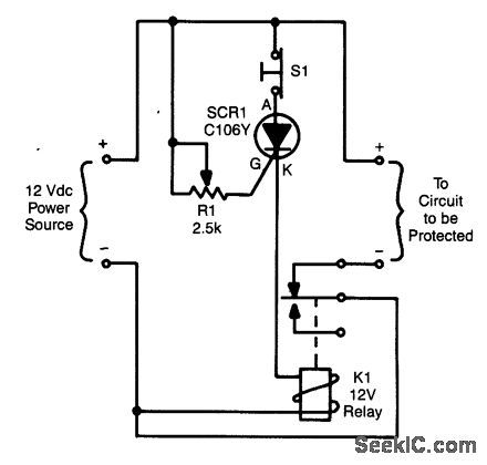
Depending on the setting of R1, when the voltage exceeds a certain amount, SCR1 triggers, which activates K1 and opens the circuit. S1 resets the SCR. (View)
View full Circuit Diagram | Comments | Reading(1020)
COMPRESSOR_PROTECTOR
Published:2009/7/9 23:13:00 Author:May
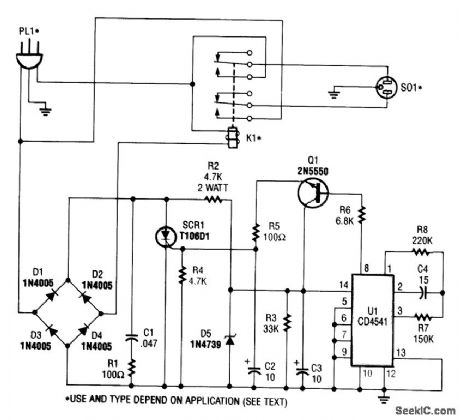
This circuit monitors the power-line (ac) voltage.When a power failure occurs,on restoration of power,the circuit adds a five-minute delay before energizing K1,which protects the compressor against limited low voltage.
U1 is a 16-stage counter with an integral oscillator that is set to divide by 8192. R7, R8, and C4 set the oscillator frequency to about 25 Hz, which produces a total count interval of 300 seconds (5Mnutes). After this time, pin 8 U1 goes high, which forward biases Q1,triggers SCR1,and activates K1. Up to 30 A can be switched.
(View)
View full Circuit Diagram | Comments | Reading(1876)
3_μP_I_O_LINE_PROTECTORS
Published:2009/7/9 22:51:00 Author:May

In Fig. 20-3(a), a 5.1-V zener diode clamps positive-going transients, and a Schottky rectifier clamps negative-going transients. The Schottky rectifier has problems at both ends or the temperature scale. At 125℃ (2570F), its leakage current can reach 50 μA when the input line is at 5 V. This leakage is not a big deal unless the input resistor has a value of 100 kΩ or more. More troubling, at temperatures below -40℃ (-400F), the Schottky rectifier's forward voltage rises to about 0.47 V, which is perilously close to the -0.50 -V max spec that most HCMOS-type μPs inputs can tolerate.
The third circuit, Fig. 20-3(c), uses two regular silicon rectifiers. One rectifier is connected in series with the input line, thereby isolating the μPs inputs from negative-going voltage spikes. The other recti-fter is in series with a 5.1-V zener, which clamps positive-going transients. (View)
View full Circuit Diagram | Comments | Reading(879)
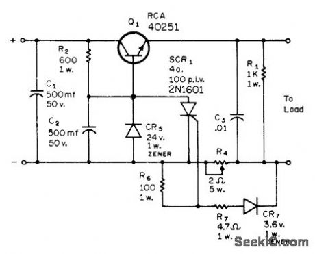
FAST_OVERVOLTAGE_PROTECTOR
Published:2009/7/9 21:21:00 Author:May
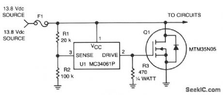


This circuit protects expensive portable equipment against all types of improper hookups and environmental hazards that could cause an overvoltage condition. It operates very quickly and does not latchup, that is, it recovers when the overvoltage condition is removed. In contrast, SCR overvoltage circuits can latch and do not recover, unless the power is removed.Here, U1 senses an overvoltage condition when the drop across R1 exceeds 2.5 V. This causes U1 to apply a positive signal to the gate of Q1, turning it on and shorting the line going to the external circuits. Fuse 1 opens if the transient condition lasts long enough to exceed the i2t rating. (View)
View full Circuit Diagram | Comments | Reading(1184)
Home booster pump protection circuit diagram
Published:2011/8/2 2:37:00 Author:Rebekka | Keyword: Home booster pump protection
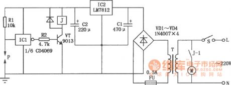
The power supply switch S will be closed if the water pipe has not water, P and the ground is similar to insulation condition, the inverter ICl inputs high, outputs low, VT cuts off, J is released. Its tragger J-1 cuts off, M booster pump is not running avoiding pump idling. If the pipe has water, P and steel shell pass the water and resistance will be conducted, then ICl input is low level and output is high level, VT will be conducted, J pulls in, M operates normally. IC1 uses CD4069 six-inverter, the one shown in the figure only uses one group of inverters, and the rest 5 groups of inverters is vacant(Connect all the input ends to the ground to prevent interference.) P is the detection sensor when there is not water, you need to make it by yourself. Methods: Drill a hole in the pipe, spark plugs into the car, pay attention to the pad to prevent leakage, eads to P pole at the spark needle, water pipe(steel) chassis can connect to the ground. (View)
View full Circuit Diagram | Comments | Reading(1330)
Current three-phase motor phase-failure protection circuit diagram
Published:2011/8/2 2:39:00 Author:Rebekka | Keyword: Current three-phase motor, phase-failure protection
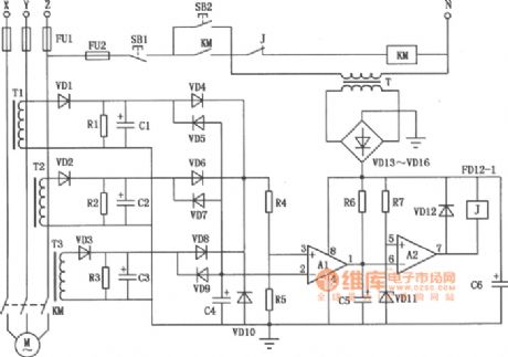
The production of transformer Tl ~ T3 can use the ring ferrite core which is easy to be purchased on the market. It uses Φ0.25mm high-strength wire wound with 150 to 250 turns. The number of the turns is determined by the motor power. If the motor power is low, you can wound more turns. The power supply line passes the ring. The capacitors C1 ~ C3 use the 10μF/25V electrolytic capacitors. C4 uses 0.1μF/63V ceramic chip capacitor; C6 uses 470μF/25V electrolytic capacitor; C5 is the interference absorption capacitor, when the action is too sensitive, it can increase the capacitance value of C5, conversely it will reduce the value of C5, its range is 4.7 ~ 33μF/25V. Resistors Rl = R2 = l.2kΩ, R4 = 390kΩ, R5 = 680kΩ, R6 = 15kΩ, R7 = 2kΩ, the nominal power resistor is 1/8W RJ. Zener VD11's regulator value is about 8V. Other diodes use 1N4004. (View)
View full Circuit Diagram | Comments | Reading(4347)
High power DC motor over-current protection circuit diagram
Published:2011/8/2 2:56:00 Author:Rebekka | Keyword: High power DC, motor over-current protection
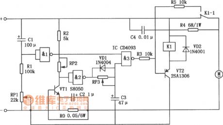
In order to prevent the motor generating high current and make the circuit work inappropriately. the Cl, Rl, RPl and NAND gate form the starting protection time delay circuit. When the motor starts, there is not voltage at Cl. At this time NAND gate 1 outputs low level, NAND gate 3 outputs high level, it makes the VT2 in the off mode, then the relay Kl does not work, andits contact stillkeeps the closed mode. The DC motor gets normal power supply. When the Cl terminal voltage rises gradually to a certain value, the NAND gate 1 is overturned, the output terminal turns to high level, the start protection circuit stops to work. After that the output mode of NAND gate 3 is the current detection circuit control composed of the RP2, R2, VTl and Ro. (View)
View full Circuit Diagram | Comments | Reading(3451)
Temporary power failure protection and death protection circuit diagram
Published:2011/8/2 2:52:00 Author:Rebekka | Keyword: Temporary power failure protection , death protection
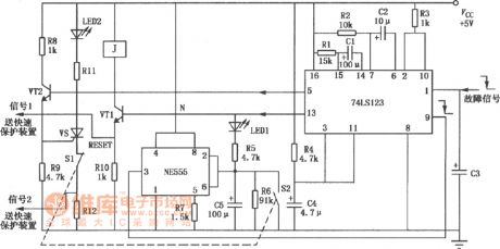
Most of the over-current, overvoltage protection of the power supply will stop working after the power failure, the output will be zero, and then it can be manually reset to work again; Or it only has temporary protection that will stop the power output after the failure happened. After the delay time, the power supply will automatically return to work. But in many devices, they require temporary protection and the die protection. For example, it requires the power to allow the load transient ignition and overcurrent. (View)
View full Circuit Diagram | Comments | Reading(778)
Machine tool magnetic chuck undercurrent protection circuit diagram
Published:2011/8/2 2:43:00 Author:Rebekka | Keyword: Machine tool magnetic chuck , undercurrent protection
The signal from the sampling circuit is amplified by voltage, whichmakes the collector potential of VTl, VT2 close to 0V, the ② pin of IC's is at the low potential , ④ pin is turned on, relay J1 gets the power. The dynamic co-contact is closed, so that the machine starts to work. When the magnetic chuck current is less than 90% of rated current (this value is adjustable), IC's ④ pin is stopped. J1 is off, the machine feed-through circuit is off at the same time. The feed-though system stops working, thus avoids the accident. This circuit IC uses TWH8751 type, VTl uses 9013-type, VT2 uses 3DGl2 type, VDl uses 24V, 1W. VD2 uses lN4148 type, relay J1 uses JTX-24 type. (View)
View full Circuit Diagram | Comments | Reading(1854)
OVERLOAD_PROTECTION
Published:2009/7/8 23:15:00 Author:May
When critical current is exceeded, SCR1 condtlcts and reduces base-ground voltage of Q1 cutting it off. Load current then drops to very low value, and Q1 is protected. Operation is restored by turning off current supply to power transformer after clearing short-circuit condition.-R. Phelps, Jr., Protective Circuits for Transistor Power Supplies, CQ March 1973, p 44-48 and 92. (View)
View full Circuit Diagram | Comments | Reading(0)
Three-phase motor phase failure protection circuit diagram
Published:2011/8/2 2:23:00 Author:Rebekka | Keyword: Three-phase motor, phase failure protection
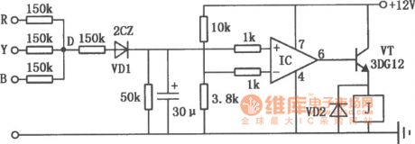
The circuit is composed of general purpose integrated operational amplifiers. The circuit is shown as above. It can be used in a variety of three-phase motor phase protections. IC uses a typical general-purpose integrated operational amplifiers, such as 5G24, BG305, FC4, F006, XFC77 or other foreign products μA741 etc. The relay J can use DC l2V operating voltage, the DC resistance is 200Ω DC relay. (View)
View full Circuit Diagram | Comments | Reading(3911)
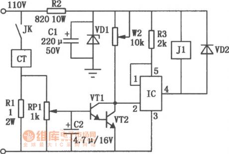
Automatic reset over-voltage protection circuit diagram
Published:2011/8/3 2:40:00 Author:Rebekka | Keyword: Automatic reset, Over-voltage protection
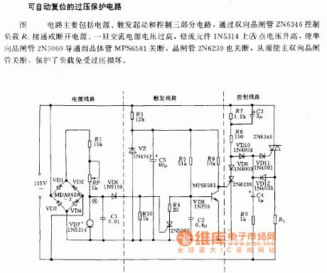
The circuit includes 3 circuit parts:power supply, trigger start and control. The power supply switch of the load R1 is controlled by bidirectional thyristor ZN6346. When the AC voltage is over high, the A point voltage of steady flow component 1N5314 will rise and the unidirectional thyristor will be conducted and the transistor will be closed. The main bidirectional thyristor will be closed at the same time, the load will be protected from damaging. (View)
View full Circuit Diagram | Comments | Reading(1282)
SERVO_SENSED_HEATER_PROTECTOR
Published:2009/7/7 23:03:00 Author:May
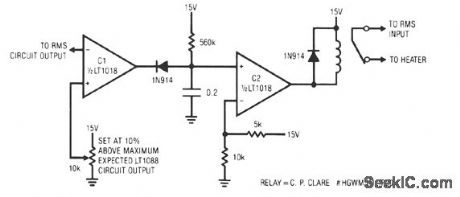
This circuit responds quickly enough to prevent damage from most overloads. C1's input is connected to the output of the LT10ss servo circuit. If the LT1088 circuit's output exceeds the threshold at C1's other input, C1 trips, discharging the 2-μF capacitor. This causes C2's output to become low, energize the relay, and break the heater circuit. The 560-KΩ resistor provides a long recharge for the capacitor, preventing chattering action. This arrangement's speed of response is limited by the rms circuit's slew rate, about 0.2 V/ms. For reasonable overloads, the LT1088's temperature increases about 1°C/ms. A 10-V LT1088 output step takes 50 ms, causing a temperature rise of about 50°C. (View)
View full Circuit Diagram | Comments | Reading(787)
STALLED_MOTOR_PROTECTION
Published:2009/7/7 4:42:00 Author:May
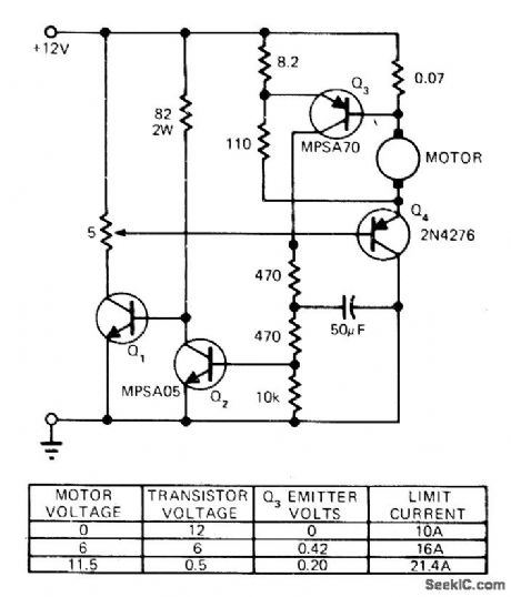
Modification of basic speed control circuit for small DC permanent-magnet motors provides maximum current limit under normal conditions and reduced current limit under stall conditions, to limit dissipation of series transistor Q4, to safe value. When motor stalls, motor voltage falls, reducing voltage and motor current required to turn on Q3 and thereby limiting stalled-motor current,-D. Zinder, Current Limit and Foldback for Small Motor Control, EDN Magazine. May 5, 1974, p 77 and 79. (View)
View full Circuit Diagram | Comments | Reading(2662)
OPTOISOLATOR_INPUT_PROTRCTION
Published:2009/7/6 7:19:00 Author:May

Combination of diode and transistor limits input current to LED of Motorola MOC3011 optoisolator to safe maximum of less than 15 mA for input voltage range of 3-30 VDC. Circuit also protects LED from accidental reversal of polarity.-P.O 'Neil, “Applications of the MOC3011 Triac Driver,” Motorola, Phoenix, AZ, 1978, AN-780, p 4. (View)
View full Circuit Diagram | Comments | Reading(783)
| Pages:4/12 123456789101112 |
Circuit Categories
power supply circuit
Amplifier Circuit
Basic Circuit
LED and Light Circuit
Sensor Circuit
Signal Processing
Electrical Equipment Circuit
Control Circuit
Remote Control Circuit
A/D-D/A Converter Circuit
Audio Circuit
Measuring and Test Circuit
Communication Circuit
Computer-Related Circuit
555 Circuit
Automotive Circuit
Repairing Circuit