
Protection Circuit
Index 10
Motor protector circuit diagram 12
Published:2011/5/21 1:47:00 Author:Lucas | Keyword: Motor protector
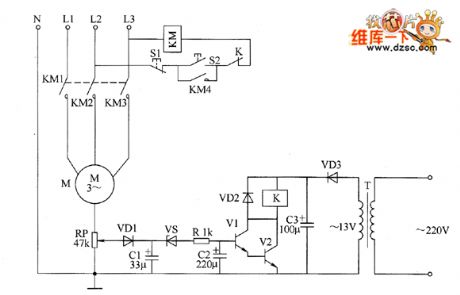
The motor protector circuit is composed of the power supply circuit and voltage detection control circuit, the circuit is shown as the chart. Power circuit is composed of the power transformer T, rectifier diode VD3 and filter capacitor C3. Voltage detection control circuit is composed of the potentiometer RP, diodes VD1, YD2, capacitors C1, C2, voltage regulator diode vs, resistor R, transistors V1, V2 and relays K. KM is the the original AC contactor in the motor control circuit, S1 and S2 are the stop button and start button respectively in the original motor control circuit of motor. AC 220V voltage is bucked by T, half-wave rectified by VD3 and filtered by C3 to provide DC operating power for K and its driving circuit.
(View)
View full Circuit Diagram | Comments | Reading(830)
Op amp differential mode voltage breakdown input stage protection measure circuit 1
Published:2011/5/17 2:07:00 Author:Rebekka | Keyword: Op amp, differential mode v, oltage breakdown , input stage, protection measure
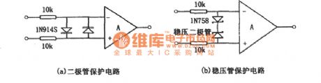
The over-voltage protection circuit that does not add an internal protection measures is shown as figure (a), (b). Figure (a) is the diode protection circuit. Figure (b) is regulator protection circuit. In the specific application, you only need to select one of them. The resistance shown in the figure is limiting current clamp resistance. Its value is up to 10kΩ and the offset voltage will not decrease. In practical applications. The input end of resistance may be the signal input. Usually, to improve the DC accuracy, you can access the same resistance to each input end. In some cases, you only need to input resistor and feedback resistor to achieve the limit of clamping diode current. It can save one or two resistors. (View)
View full Circuit Diagram | Comments | Reading(1055)
Op amp power supply voltage polarity reverse protection circuit diagram
Published:2011/5/17 3:21:00 Author:Rebekka | Keyword: Op amp, power supply voltage, polarity reverse protection
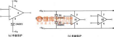
The protection circuit of the op amp power supply reverse polarity is shown in figure (a), (b). Figure (a) is protection circuit of the single-stage amplifier, Figure (b) is the multi-stage amplifier circuit protection circuit. If the integrated operational amplifier without power polarity protection. The power supply voltage polarity is reversed, a destructive current will pass the chip (usually when the chip is in normal operation, there will be a large current passes the reverse-biased diode). The principle of the protection circuit is very simple. For figure (a), it uses the one-way conductive of the diode, so that the reversed power supply voltage can not be added to the integrated operational. For figure (b), it is concentrated protection circuit. When the power supply voltage is reversed, the diodes D1 and D2 turns on. (View)
View full Circuit Diagram | Comments | Reading(1672)
Op amp power supply over-voltage protection circuit diagram
Published:2011/5/17 3:44:00 Author:Rebekka | Keyword: Over-voltage protection , Op amp power supply
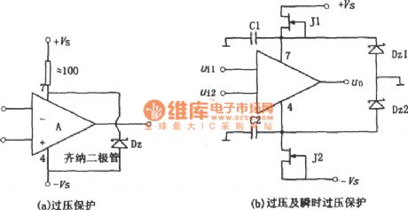
Power supply over-voltage protection circuit is shown as above. Figure (a) is simple and practical over-voltage protection circuit, which uses Zener diode Dz to limit the integrated operational amplifier supply voltage within the safe voltage limit. The selection method of the regulator of the operating voltage can be based on the following formula: Vz ≤ 2Vsmax. Normally Vz should be close or equal to the total power supply voltage, its current limiting resistor R should use high-power resistance, and resistance value should ensure the voltage regulator tube is able to work properly. Figure (b) shows the two functions that overvoltage protection and transient voltage protection. When it is in normal operation mode, the tube pressure of J1 and J2 should be decrease, ± VSD value is low, so the two regulators Dz1 and Dz2 do not work, so none of them is breakdown. (View)
View full Circuit Diagram | Comments | Reading(1989)
MT8880 Interface Circuit
Published:2011/5/16 9:12:00 Author:Michel | Keyword: Interface Circuit
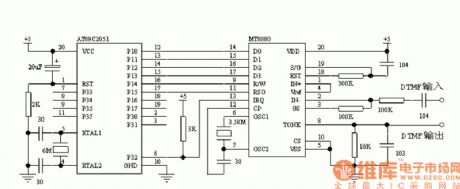
View full Circuit Diagram | Comments | Reading(1995)
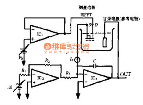
PH Meter Circuit
Published:2011/5/16 9:04:00 Author:Michel | Keyword: PH Meter, Circuit
View full Circuit Diagram | Comments | Reading(1508)
Thermal protection system circuit composed of MIC2951
Published:2011/5/12 20:52:00 Author:Rebekka | Keyword: Thermal protection system
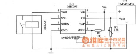
Thermal protection system circuit composed of MIC2951 is shown as above. The temperature threshold of the circuit is set by the adjustment of R2. (View)
View full Circuit Diagram | Comments | Reading(735)
Humidity Sensor Interface Circuit
Published:2011/5/15 5:46:00 Author:Michel | Keyword: Humidity Sensor, Interface Circuit
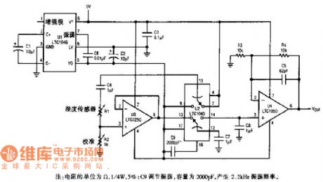
View full Circuit Diagram | Comments | Reading(778)
Power supply over voltage detection and time delay protection circuit diagram
Published:2011/5/16 3:19:00 Author:Rebekka | Keyword: over voltage detection , time delay protection
For some electrical equipments, the operating supply voltage range is strictly limited. Over-voltage or under-voltage will affect the work or even damage the equipment. The following shows a over-voltage and under voltage detection and time delay protection circuits. It can cut off the power supply when it is over-voltage or under-voltage. And it can start automatically after a period of delay. It is composed of two four-two input NAND gates CD4011. The over voltage and under-voltage detection circuit is composed of D1-D3 and RPl, RP2. D4 is trigger circuit. The relay driver circuit is composed of D7, D8 and transistor VT. The time relay restart circuit is composed of D5, D6 and R4, C5. (View)
View full Circuit Diagram | Comments | Reading(1835)
Home appliances overvoltage protector circuit diagram
Published:2011/5/15 5:55:00 Author:Rebekka | Keyword: Home appliances , overvoltage protector
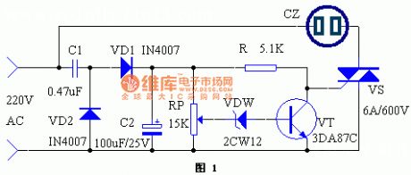
When the voltage suddenly rises because of some reason,household appliances such as the running refrigerators, washing machines, televisions, stereos, computers will face varying degrees of damage, even catch serious fire, causing great economic loss. This paper describes a simple over-voltage protection device, which provides protective effects on the appliance. When the voltage exceeds the allowable range, thepower supply will automatically cut off. Once the voltage turns to normal, the power can be automatically switched back. (View)
View full Circuit Diagram | Comments | Reading(2079)
SBC overvoltage protection circuit diagram
Published:2011/5/15 5:14:00 Author:Rebekka | Keyword: SBC overvoltage protection
The circuit is shown as above. It can use +5 V operating voltage SBC power supply. It can prevent the damage of the SBC to +5 V the entire SBC because of overvoltage. (View)
View full Circuit Diagram | Comments | Reading(790)
Optically isolated input protection circuit diagram
Published:2011/5/13 1:31:00 Author:Ecco | Keyword: Optically , isolated , input , protection
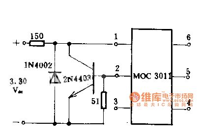
Diodes and transistors form the circuit, when the input voltage range is 3 ~ 30V DC, the input current of MOC3011 optical isolator LED is limited to be less than the safety limit of 15mA. In the case of reverse polarity accident, the circuit can protect the light-emitting diodes.
(View)
View full Circuit Diagram | Comments | Reading(1202)
Operational amplifier differential-mode voltage puncture input protection measures circuit diagram 2
Published:2011/5/11 3:48:00 Author:Rebekka | Keyword: protection measures , Operational amplifier, puncture input
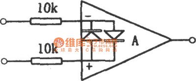
The protection circuit of internal protective measures integrated chip (such as the 741 series and the type of integrated FET input op amp) is shown as above. Its limiting current resistor can be up to 10kΩ.
(View)
View full Circuit Diagram | Comments | Reading(733)
Power capacitor compensation protection circuit diagram
Published:2011/5/11 4:25:00 Author:Rebekka | Keyword: Power capacitor compensation protection
The circuit is shown in the figure. It is used in power supply circuit. It can cut off the power when it is overvoltage or power-off phase. So that the power capacitor can be protected. (View)
View full Circuit Diagram | Comments | Reading(728)
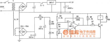
Overheat protection system circuit composed of MIC2951
Published:2011/5/11 4:36:00 Author:Rebekka | Keyword: Overheat protection system
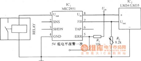
The figure shows the overheat protection system circuit composed of MIC2951. The temperature threshold value of circuit is set by the adjustment R2. (View)
View full Circuit Diagram | Comments | Reading(835)
SG201 leakage protection IC diagram
Published:2011/5/9 2:23:00 Author:Ecco | Keyword: leakage protection , IC
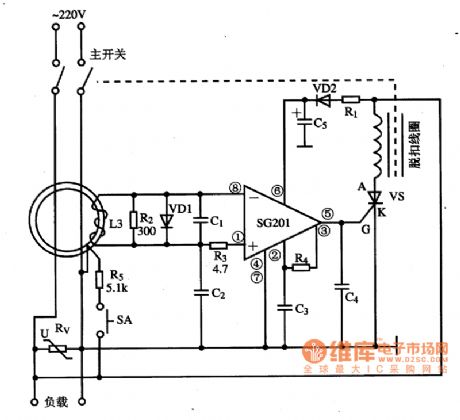
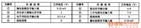
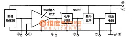
SG201 is the specific leakage protection integrated circuit, which is widely used in a variety of leakage protection. 1. Features of functionsSG201 IC includes voltage regulator circuit, reference voltage circuit, the differential amplifier circuit, level judging and shaping output circuit, the internal block circuit diagram is shown as the chart. 2. Pin functions and data SG201 integrated circuit uses 8-pin dual in-line package, the pin functions and data are listed in table. Operating current is 1.8 ~ 2.5mA, so the static power consumption is low. 3. The typical application circuit The typical application circuit of SG201 IC leakage protection circuit is shown in Figure 1.
(View)
View full Circuit Diagram | Comments | Reading(1019)
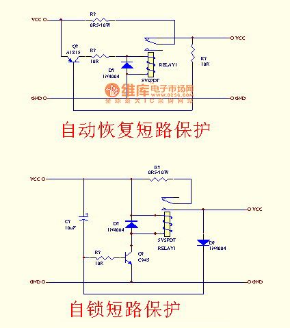
Short-circuit protection circuit with relay
Published:2011/5/9 4:13:00 Author:Rebekka | Keyword: Short-circuit protection , relay
View full Circuit Diagram | Comments | Reading(3807)
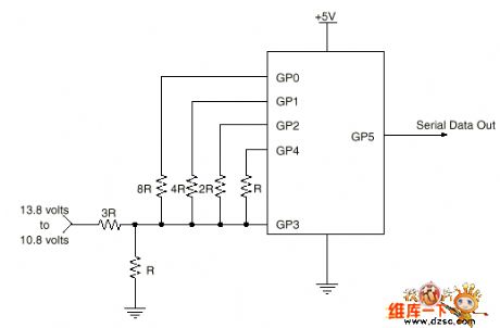
Singlechip storage battery monitor circuit based on PIC12C508
Published:2011/5/3 3:51:00 Author:May | Keyword: singlechip, battery monitor
Brief Introduction
Normally, its rating value is 12V in 12V lead acid storage battery of trucks, cars, entertainment cars and uninterruptible power supply. This circuit monitors battery, charging and discharging curve, and it gives present voltage value and predicts the leavings time to supply end.
The voltage is 13.8V when 12V battery is fully charged, and it is 10.8V when 12V battery is fully released. It is linear in 3V range. It can use to predict the time value UPS
The diagram explains one bit A/D converter. It storages high, low and open three states in the resistor of single chip’s GP0, GP1, GP2, and GP4 pins. It allows GP3 input end as voltage comparator.
The circuit diagram:
(View)
View full Circuit Diagram | Comments | Reading(1375)
The protection circuit diagram composed of negative resistance leds
Published:2011/5/3 1:33:00 Author:Ecco | Keyword: protection circuit , negative resistance , led
View full Circuit Diagram | Comments | Reading(586)
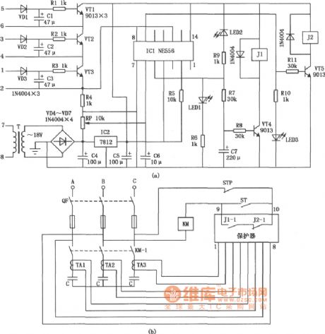
Motor protector 11
Published:2011/4/27 21:18:00 Author:Ecco | Keyword: Motor protector
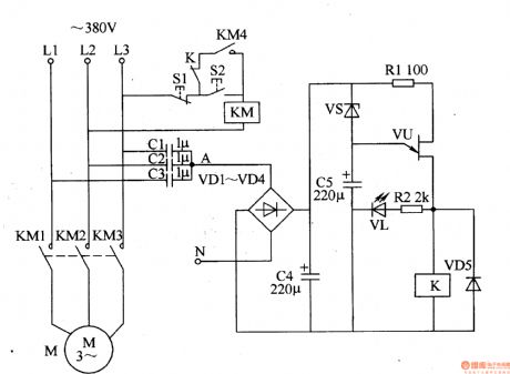
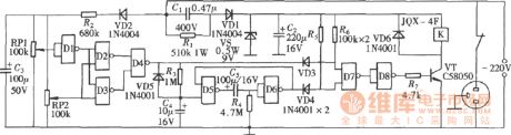
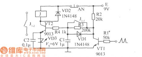
The motor protector described in the example has the protection function of phase auto delay and the features of simple circuit, without an external power supply, and it is suitable for all kinds of automatic (or manual) three-phase AC motor control equipment.
The working principle
The motor circuit protector circuit consists of capacitors CI-C5, diodes VDl-VD5, resistors Rl, R2, zener diode VS, light-emitting diode VL, VU prison junction transistors and relay K, it is shown as Figure 8-47.
When the three-phase power ofLl-L3 being normal, the AC voltage on junction point A of capacitors Cl-C3 will be lower, the voltage is rectified by the VDl-VD4, after being filtered by C4, it is insufficient to turn on VS and VU, K does not pull, the motor M operates normally.
When the three-phase power in the absence of a phase voltage, the place between the zero line and A point will quickly produce l2V AC voltage. This voltage is rectified by VDl-VD4 and filtered by C4, so that making VS breakdown conduction, C5 starts charging, after delaying several seconds (after C5 charging), VU turns, VL is lit, K pulls in, the contacts are off, so that the AC contactor KM releases, cutting off the working power source of motor M.
When the three-phase power is restored to normal, after a short delay, VU is off, K releases, then you can press the start button S2 to restart the motor. (View)
View full Circuit Diagram | Comments | Reading(1344)
| Pages:10/12 123456789101112 |
Circuit Categories
power supply circuit
Amplifier Circuit
Basic Circuit
LED and Light Circuit
Sensor Circuit
Signal Processing
Electrical Equipment Circuit
Control Circuit
Remote Control Circuit
A/D-D/A Converter Circuit
Audio Circuit
Measuring and Test Circuit
Communication Circuit
Computer-Related Circuit
555 Circuit
Automotive Circuit
Repairing Circuit