
Protection Circuit
Index 2
CIRCUIT PROTECTS BATTERY POLARITY REVERSAL
Published:2012/9/9 20:33:00 Author:Ecco | Keyword: PROTECTS , BATTERY , POLARITY REVERSAL
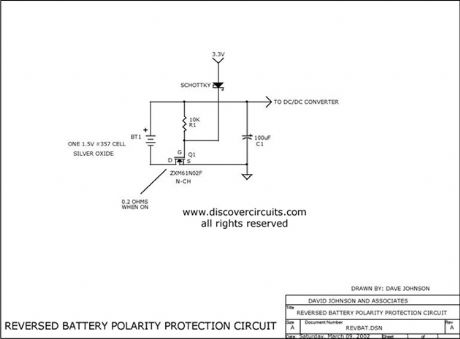
This simple circuit can protect a sensitive electronic circuit from an accidental connection of a battery with a reversed polarity. The N-channel FET connects the electronic device to the battery only when the polarity is correct. The circuit shown was designed for a device powered from a single 1.5 volts button cell battery. However, the circuit will operate with higher voltages as well.
Source: discovercircuits (View)
View full Circuit Diagram | Comments | Reading(2185)
CIRCUIT PROTECTS FROM BATTERY POLARITY REVERSAL
Published:2012/9/5 20:44:00 Author:Ecco | Keyword: CIRCUIT , PROTECTS , BATTERY POLARITY REVERSAL

This simple circuit can protect a sensitive electronic circuit from an accidental connection of a battery with a reversed polarity. The N-channel FET connects the electronic device to the battery only when the polarity is correct. The circuit shown was designed for a device powered from a single 1.5 volts button cell battery. However, the circuit will operate with higher voltages as well.
Source: discovercircuits (View)
View full Circuit Diagram | Comments | Reading(1284)
Y-connection motor protection circuit
Published:2012/8/11 1:35:00 Author:Ecco | Keyword: Y-connection , motor , protection
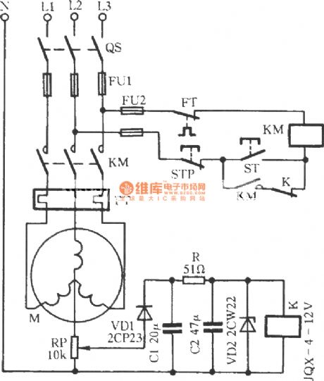
In the circuit shown as the figure, pressing the ST will make KM coil get electric and pull in; loosening ST will allow the KM to get self-protection, then motor M runs. When one phase of three-phase alternating current circuit is dieconnected, then motor's midpoint will generate potential difference. The voltage will be rectified and stabilized to make relay K be energized, then the power of M is cut to to protect the motor stator windings from burning. The circuit is suitable for motors with power lowering than 7.5kW.
(View)
View full Circuit Diagram | Comments | Reading(2066)
The protection circuit composed of negative resistance LED
Published:2012/7/18 2:50:00 Author:Ecco | Keyword: protection circuit , negative resistance, LED

View full Circuit Diagram | Comments | Reading(965)
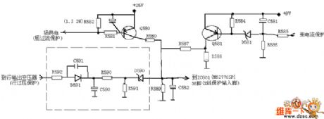
Starting protection circuit
Published:2011/11/22 0:15:00 Author:May | Keyword: Starting protection
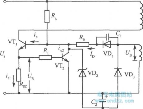
When the circuit is in the state of normal voltage regulation, controlling circuit can always keep VT1 base current in a fixed number. But when the power supply is breaking over, it will havea large starting current on transistor VT1. In order to prevent burning out this transistor VT1 by this current, we must take protection measure. The simplest protection is shown in the diagram, and it is added a resistor on the emitter of VT1.
When VT1 tube's current is enlarging, the voltage generatedby resistor Rsc is enlarging, VT1's base potential increases, driving current Id decreases. So VT1's base current is limited, VT1's collector current is limited to a fix number. We can know from the diagram, if drop voltage generated by switching transistor VT1's collector current on resistor Rsc is more than VT2's Ube2, VT2 is breaking over, it canmake VT1's base current divide a part, thereby it can make sure the collector current of VT1be less than protection value. (View)
View full Circuit Diagram | Comments | Reading(886)
HD-3A energy-saving quota three-phase power supply protector circuit
Published:2011/10/27 22:12:00 Author:May | Keyword: Energy-saving quota , three-phase, power supply protector
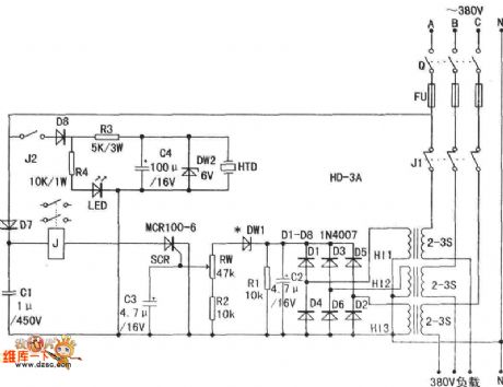
Current transformer H11-3can behomemade. People can choose transformer's iron core which is not less than 2W to wind secondaryfirstly.It usesΦ 0.12 mm varnished wire to wind1,000 turns. The primary uses Φ 1 ~ 4mm plastic wireto wind2 - 3 turns. It also can use current transformer. Finished current transformer induced voltage is quite high.
(View)
View full Circuit Diagram | Comments | Reading(2253)
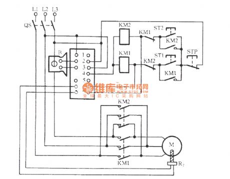
QM9403 three-phase motor protection circuit
Published:2011/12/7 2:04:00 Author:Ecco | Keyword: three-phase, motor protection circuit
View full Circuit Diagram | Comments | Reading(2458)
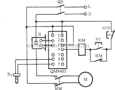
QM9403 single-phase motor protection circuit
Published:2011/12/7 1:49:00 Author:Ecco | Keyword: single-phase , motor protection
View full Circuit Diagram | Comments | Reading(2177)
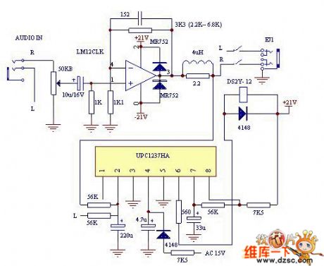
UPC1237 speaker protection circuit ( LM12 power amp circuit )
Published:2011/12/9 0:57:00 Author:Ecco | Keyword: speaker, protection circuit , power amp
View full Circuit Diagram | Comments | Reading(28159)
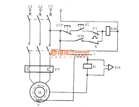
Motor immersion protection circuit
Published:2011/11/8 21:11:00 Author:Ecco | Keyword: Motor immersion protection
View full Circuit Diagram | Comments | Reading(1208)
Motor overload protection circuit
Published:2011/11/8 20:32:00 Author:Ecco | Keyword: Motor overload protection
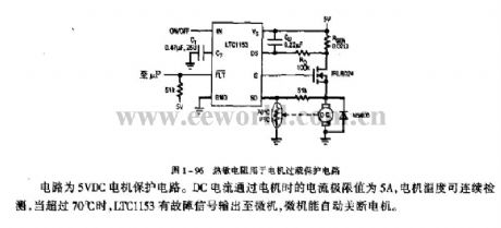
The circuit is the 5VDC motor protection circuit. The current extreme of DC current passing the motor is 5A, and the motor temperature is monitoring continuously, when it is more than 70 ℃, LTC1153 has fault signal sending to the computer, then the computer automatically shut off the machine.
(View)
View full Circuit Diagram | Comments | Reading(1784)
Timing automatic AC shutdown circuit diagram
Published:2011/10/31 2:22:00 Author:May | Keyword: Timing , automatic AC shutdown
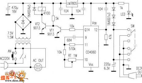
Befeore it gets power, the timing clock generator is reset by the capactor of the pin 12 of IC, and the various output stages are in low potential. Because out-port Q14 outputs low level, the triode VT1 closes, the VT2 is breakover, relay J gets the electricity, then the contacts pull in. AC OUT is the AC output socket, which may serve as the head light, miniature ceiling fan and other AC electric appliances without timing device. The CD4060 integrated circuit has the 14-level binary counting/divider with clock pulse oscillator. Adjusting potentiometer RT can change the fixed time, and the timing time is approximately between 20 second ~4.5 hour.
(View)
View full Circuit Diagram | Comments | Reading(1138)
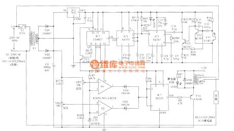
Remote control load protection circuit diaram
Published:2011/9/26 21:55:00 Author:Rebekka | Keyword: Remote control load protection
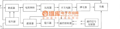

Remote control block diagram of the load protection.
Remote control transmitter.
Remote control receiver and load protection circuits.
Load protection's main functions are: (1) When the power supply voltage is too low or too high, the load will be off automatically; (2) When the power supply voltage is restored, the load power will be connected automatically; (3)Ot provides powerfor normal indication, When the voltage is too low or too high, the light will turn off; (4) Using remote control to remote control power.
(View)
View full Circuit Diagram | Comments | Reading(1352)
MX-5 movement protection schematic diagram
Published:2011/10/17 2:13:00 Author:Ecco | Keyword: movement protection
View full Circuit Diagram | Comments | Reading(764)
Lightning protection circuit diagram for equipments
Published:2011/9/25 21:22:00 Author:Ecco | Keyword: Lightning protection , equipments
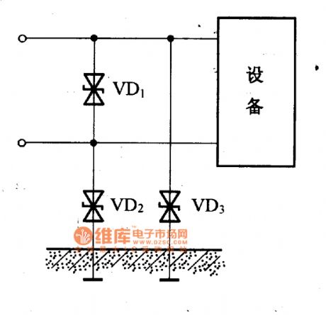
When lightning occurs and generates the overvoltage, the over-voltage current can pass transient voltage between lines and ground to suppress diodes VD2, VD3 from connecting to the earth, and their ground voltage difference is further inhibited by the bipolar transient voltage suppression diode VD1 between two lines, so that the equipment is protected.
(View)
View full Circuit Diagram | Comments | Reading(1789)
TV lightning protection circuit diagram
Published:2011/9/25 21:29:00 Author:Ecco | Keyword: TV lightning protection
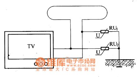
If you watch TV in thunderstorm days, lightning will damage the TV tuner by outdoor antenna. If you install the varistor in outdoor antenna, it may play a role on lightning protection. TV lightning protection circuit is shown as the chart, varistors can connect directly with the earth.
(View)
View full Circuit Diagram | Comments | Reading(2080)
Rectifier over-current protection circuit diagram
Published:2011/9/25 21:36:00 Author:Ecco | Keyword: Rectifier , over-current protection
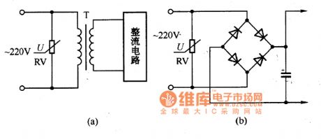
As the voltage fluctuations or man-made distribution incidents often make the power grid generate surge over-voltage phenomenon, then the electronic equipments and power transformer rectifier circuit will be damaged. If varistor is connected to the input end of rectifier diodes and power transformer to play a protective role. The circuit is shown as the chart.
(View)
View full Circuit Diagram | Comments | Reading(1670)
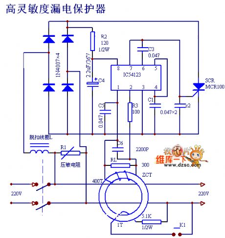
High sensitivity leakage protector circuit diagram
Published:2011/9/14 22:10:00 Author:Rebekka | Keyword: Leakage protection, leakage protector
View full Circuit Diagram | Comments | Reading(1350)
Automatic refrigerator protector circuit diagram
Published:2011/9/1 2:03:00 Author:Ecco | Keyword: Automatic refrigerator protector
View full Circuit Diagram | Comments | Reading(2409)
The remote controller of drainage and irrigation pumping station
Published:2011/9/6 4:43:00 Author:Felicity | Keyword: remote controller, drainage and irrigation pumping station
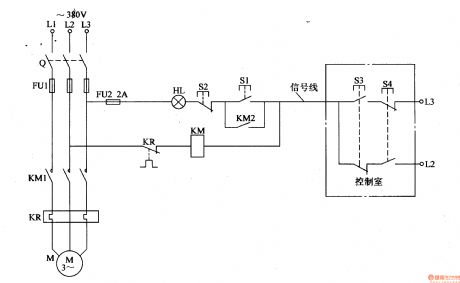
On remote start, press S3, and the phase voltage of L3 goes through the normally open contact of S3 to put on KM, And KM turns on, and the normally open contact KM1, KM2 closes and the pump motor starts. After release S3, the phase voltage of L3 goes through FU2, HL, S2, normally open contact KM2, KM and the normally close contact of KR to phase L2 to make up circuit and maintaining KM close.When it needs to stop, press S4 to make KM off and the pump motor M stops.
(View)
View full Circuit Diagram | Comments | Reading(938)
| Pages:2/12 123456789101112 |
Circuit Categories
power supply circuit
Amplifier Circuit
Basic Circuit
LED and Light Circuit
Sensor Circuit
Signal Processing
Electrical Equipment Circuit
Control Circuit
Remote Control Circuit
A/D-D/A Converter Circuit
Audio Circuit
Measuring and Test Circuit
Communication Circuit
Computer-Related Circuit
555 Circuit
Automotive Circuit
Repairing Circuit