
Protection Circuit
Index 8
Battery Protection Circuit
Published:2011/7/16 10:03:00 Author:Robert | Keyword: Battery, Protection
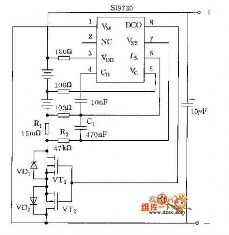
The picture shows the battery protection circuit. (View)
View full Circuit Diagram | Comments | Reading(834)
Practical Under-Voltage And Over-Voltage Protection Circuit
Published:2011/7/17 8:01:00 Author:Robert | Keyword: Practical, Under-Voltage, Over-Voltage, Protection
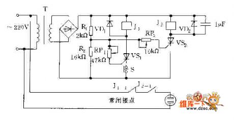
The picture shows the practical under-voltage and over-voltage protection circuit. (View)
View full Circuit Diagram | Comments | Reading(2496)
Power Over-Voltage Protection Circuit By Using μPC3423
Published:2011/7/17 8:18:00 Author:Robert | Keyword: Power, Over-Voltage, Protection
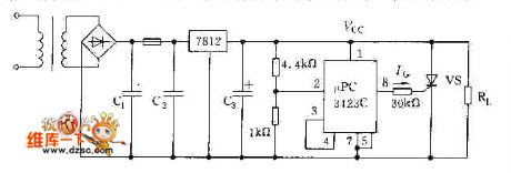
The picture shows the power over-voltage protection circuit by using μPC3423. (View)
View full Circuit Diagram | Comments | Reading(635)
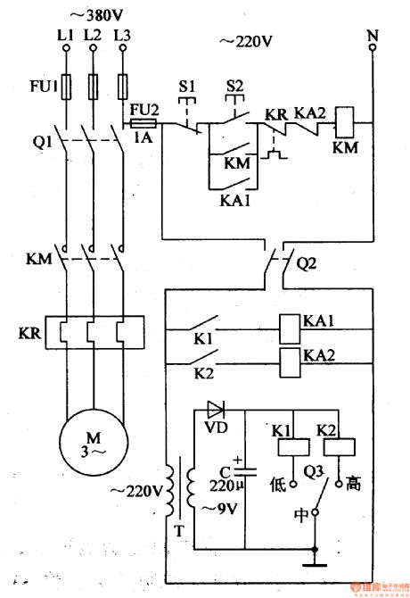
Zero-voltage motor open-phase protection circuit diagram
Published:2011/5/17 3:31:00 Author:Ecco | Keyword: Zero-voltage, motor, protection circuit, open-phase

Figure 141 shows the Zero-voltage motor open-phase protection circuit diagram. When running motor occurs single-phase outage, the protection device can automatically cut off power to avoid motor occuring open-phase running. Working principle: when normal operation, the potential of the three-phase power balance point E is zero.
(View)
View full Circuit Diagram | Comments | Reading(1712)
agricultural non-tower pressure-charged water feeder (4)
Published:2011/7/14 20:49:00 Author:chopper | Keyword: non-tower, pressure-charged
The principle of circuit This agricultural non-tower pressure-charged water feeder circuit is formed by power supply circuit and pressure measurement control circuit, as shown in figure 4-155. Power supply circuit is formed by the fuse FU2,knife switch Q2,the power transformer T,the rectifier diode VD and filter capacitor C. Pressure measurement control circuit is formed by the electric connecting pressure gauge Q3,relays K1,K2,intermediate relays M1,KA2,AC contactor KM,thermal relay KR,control buttons S1,S2,and knife switch Q1.
(View)
View full Circuit Diagram | Comments | Reading(639)
agricultural non-tower pressure-charged water feeder(3)
Published:2011/7/14 20:49:00 Author:chopper | Keyword: non-tower, pressure-charged
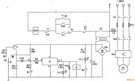
The principle of circuit This agricultural non-tower pressure-charged water feeder circuit is formed by the power supply circuit, pressure detection circuit,control circuit and indication circuit, which is shown in figure 4-154. Power supply circuit is formed by the knife switch Q1,fuses FU1,FU2 power transformer T,bridge rectifier UR and filter capacitor C. Detection circuit is formed by the electric connecting pressure gauge Q2,resistors R4-R7,normal closed contact K3 of relay K and the transistor V.
(View)
View full Circuit Diagram | Comments | Reading(842)
agricultural non-tower pressure-charged water feeder(1)
Published:2011/7/13 21:29:00 Author:chopper | Keyword: agricultural, non-tower, pressure-charged, water feeder
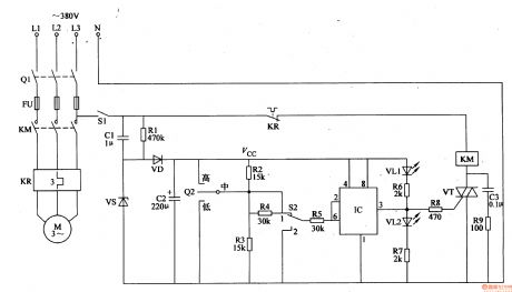
Rural water supply system adopts the non-tower pressure-charged water supply device, and drawback of this water control device is that the control contact of electric connecting pressure gauge is easy to ablate,thus thepressure will get out of control.This example describes the agricultural non-tower pressure-charged water feeder,and the control circuit adopts l2V DC voltage power supply, and the current through control contact of electric connecting pressure gauge is small,thus can avoid the control contact erosion.The circuit is stable and reliable,and production costs is low. The principle of circuit This agricultural non-tower pressure-charged water feeder circuit is formed by the power circuit and the detection control circuit,which is shown in figure 4-152.
(View)
View full Circuit Diagram | Comments | Reading(922)
timing controller(2)
Published:2011/7/13 22:02:00 Author:chopper | Keyword: timing controller

The timing controller described in this example is of functions like time display,cycle timing, single timing,and manual function,and the regular timing time is 1-90min.It can be used to control a variety of electrical equipments which should work at regular time or work intermittently. The principle of circuit The timing controller circuit is formed by the power supply circuit, the clock signal generator,counting distributor,RS trigger and the switch output circuit, which is shown in figure 4-165.
(View)
View full Circuit Diagram | Comments | Reading(715)
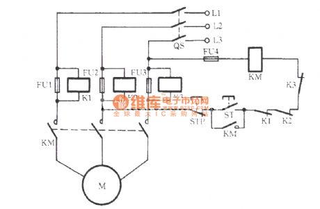
Motor protector circuit diagram 9
Published:2011/6/13 23:38:00 Author:Lucas | Keyword: Motor protector

The motor protection circuit is composed of the start control circuit, phase detection circuit and protection implementation circuit, the circuit is shown as the chart. Control circuit is composed of starter button S2 and stop button S1 and so on. Phase failure detection circuit consists of the current transformer coil TA, rectifier diode VD1, resistor R1, capacitor C and potentiometers RP1 and RP2 and so on. Protection implementation circuit is composed of the transistors V1 ~ V3, relay K, AC contactor KM and other components. Pressing the start button S2 (S2a and linkage 52b) will make the AC contactor KM and its normally open contacts (moving together contact) KM1 ~ KM4 pull in, the motor M operates to generate 1.2V induced voltage in ⒕, the voltage is rectified by VD1 to make V2 be saturated conduction. At this point, the 52b is off, V1 stops, V3 turns on, relay K pulls in and works, its normally open contact Κ is connected, hands being away the start button S2 will maintain the normal operation of motor M.
(View)
View full Circuit Diagram | Comments | Reading(2297)
Water towers water level controller circuit
Published:2011/7/8 3:23:00 Author:Fiona | Keyword: level controller
IC2 can use a variety of 555 time base integrated circuits. IC3 is the infrared receiver decoder CX20106A. IC4 can use 4N25, 4N26, PC817 and other optocoupler. Part of the infrared receiver can purchase finished infrared receiver components or integrated infrared receiver,it’s easy to produce and improve reliability. VD1, VD2 and VD3 can use infrared transmitter and receiver diodes of TVremote control. J chooses to use a new selection of memory self-locking relay,the shape of this relay is same as the general replay, the difference is that the pullis not required to maintain current,justwhen pulling and releasingit requires a certain pulse drive power, then the mechanical structure maintains locked state.
(View)
View full Circuit Diagram | Comments | Reading(1909)
UCC3895N phase shift control circuit
Published:2011/7/8 21:08:00 Author:chopper | Keyword: phase shift, control circuit
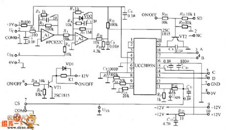
Figure shows the UCC3895N phase shift control circuit,and in order to reduce the interference of the power switching circuit, it can substrate the control circuit.Uc control input voltage of ② end of left placode can offer 0~+5V voltage by connecting 5V benchmark voltage of UCC3895N to 10kΩ adjustable resistor,can also use D/A converter to generate the control voltage. It can not join capacitor Ca in order to speed up response time. (View)
View full Circuit Diagram | Comments | Reading(1631)
traditional PWM control full-bridge circuit
Published:2011/7/9 3:12:00 Author:chopper | Keyword: traditional, PWM control, full-bridge circuit
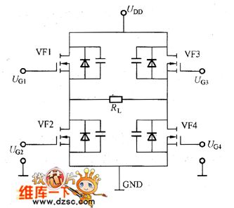
Figure shows a traditional PWM control full-bridge circuit and waveforms of control signal. As for 4 switches in the circuit,VF1 and VF4 will conduct meanwhile(positive output), and VF2 and VF3 will conduct meanwhile(negative output). Change the conduction and close time of switch tube as well as duty ration to control the output voltage.
(View)
View full Circuit Diagram | Comments | Reading(756)
NE555 Overvoltage and Overcurrent Protection Circuit
Published:2011/6/23 10:10:00 Author:Michel | Keyword: Overvoltage, Overcurrent, Protection Circuit
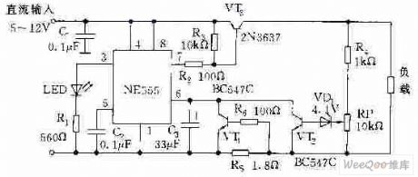
The picture is the overvoltage and overcurrent protection circuit composed of NE555. VT1 and VT ends, NE555 resets, and all of the transistor is in conduction mode.It absorbs current from VT3 which makes VT stay in saturation condition and 5~12V DC power supply provides load via VT3.When load current exceeds rating value and voltage on RS increases which makes VT1 conduct and NE555 be triggered and then VT3 stops,load power supply cuts off.At the time,NE555 is in monostable condition and NE555 is triggered again VT3 continuely isolates load from power supply as long as the load flow does not rule out. (View)
View full Circuit Diagram | Comments | Reading(3043)
Loom Controller
Published:2011/7/7 2:32:00 Author:Felicity | Keyword: Loom Controller
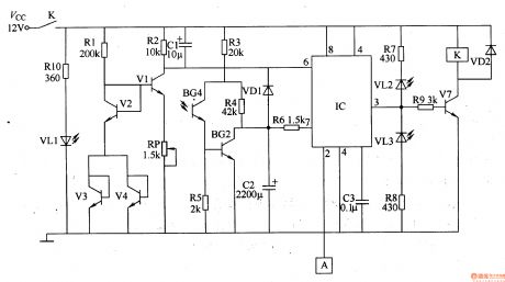
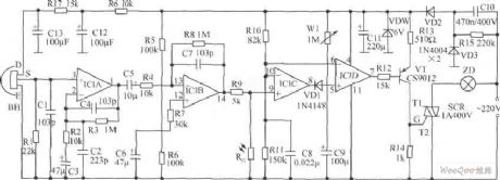
Work of the circuit The circuit consists of touch control circuit, the light control circuit, overheat protection circuit, working status indication circuit and control implementation circuit. (It is showed in picture 8-132.) Touch control circuit consists of touching electrodes A and the circuit inside 2 feet of time-base integrated circuit IC. The light control circuit consists of infrared emitting diode VLl, infrared phototransistor, V5, transistor V6, resistors RlO and R3-R6 and circuit within IC’s pin 7. Overheat protection circuit consists of transistor Vl-V4, diode VD1, resistors Rl and R2, capacitor Cl and C2, potentiometer RP and circuit within IC’s pin 6. Working status indication circuit consists of resistors R7, R8 and LED VLl, VL2. Control implementation circuit consists of transistor V7, relay K, resistor R9 and diode VD2. (View)
View full Circuit Diagram | Comments | Reading(993)
Intermittent Controller (the 1st)
Published:2011/7/10 22:42:00 Author:Felicity | Keyword: Intermittent Controller,

Work of the circuit
The circuit consists of power circuit, timer and control implementation circuit. (It is showed in picture 8-96.)
Power circuit consists of Capacitors C2-C4, resistors R3-R5, bridge rectifier, UR, voltage regulator diode VS and power indicator LED VL.
Timer circuit consists of counter / divider integrated circuit IC, capacitor Cl, diode VD2-VD4 and resistors Rl, R2, R6. Clock oscillator circuit consists of Rl、R2、Cland IC internal circuit.
Control implementation circuit consists of transistor V, resistor R7, diode VDl, relay K and AC contactor KM. (View)
View full Circuit Diagram | Comments | Reading(811)
Intermittent Controller (the 2nd)
Published:2011/7/10 22:43:00 Author:Felicity | Keyword: Intermittent Controller,
Work of the circuit
The circuit consists of power circuit, timing control circuit and control implementation circuit. (It is showed in picture 8-97.)
Power circuit consists of fuse FU, power transformer T, bridge rectifier, UR, filter capacitor C3, three-terminal voltage regulator integrated circuit IC2, current limiting resistor Rl and the power indicator LED VLl.
Timing control circuit consists of time-base integrated circuit ICl, potentiometer RPl and R Robinson, resistor R2, work instructions LED VL2 and capacitors Cl, C2.
Control implementation circuit consists of relay K, AC contactor KM and diode VD. (View)
View full Circuit Diagram | Comments | Reading(886)
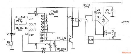
Intermittent Controller (the 3rd)
Published:2011/7/10 22:45:00 Author:Felicity | Keyword: Intermittent Controller,
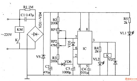
Work of the circuit
The circuit consists of power circuit, timing control circuit and control implementation circuit. (It is showed in picture 8-98.)
Power circuit consists of Buck capacitor Cl, resistors Rl, R5, rectifier diode VDl-VD4, voltage regulator diode VS, power indicator light-emitting diode VL1and filter capacitor C2.
Timing control circuit consists of time-base integrated circuit IC, resistors R2-R4, capacitors C3, C4, potentiometer RPl, RP2, diode VD5, VD6 and light-emitting diode VL2.
Control implementation circuit consists of diode VD7, relay K and AC contactor KM. (View)
View full Circuit Diagram | Comments | Reading(840)
Fuse voltage control signal relay open-phase protection circuit
Published:2011/7/10 Author:Lucas | Keyword: Fuse voltage , control signal, relay , open-phase protection
View full Circuit Diagram | Comments | Reading(1103)
Computer Protection Circuit
Published:2011/7/6 8:55:00 Author:Robert | Keyword: Computer, Protection
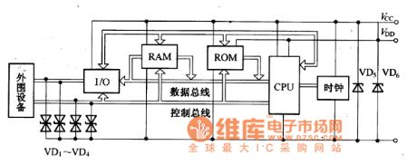
The computer protection circuit is shown in the picture. There are bipolar transient voltage suppression diodes VD1-VD4 connecting with the interface circuit between the computer and the peripherals. They could suppress the over-voltage pulses coming from the computer's peripheral devices. Also there are unipolar transient voltage suppression diodes VD5, VD6 separately being installed in the computer working power's input port. They could suppress the over-voltage pulses coming from the power.
The picture shows the computer protection circuit. (View)
View full Circuit Diagram | Comments | Reading(804)
MC3423 overvoltage protection circuit, main features and pin of power monitor
Published:2011/7/4 22:34:00 Author:Lucas | Keyword: overvoltage , protection circuit, main features , pin , power monitor
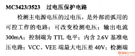
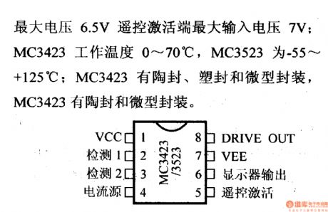
MC3423/3523 over-voltage protection circuitIt is a controllable circuit which is used for external arc extinction to detect over-voltage of main power supply voltage; it can change the detection voltage; output current is 300mA; control terminal is TTL level; it is embedded 2.6V voltage reference circuit; the maximum voltage difference between VCC and VEE ends is 40V; the maximum input voltage of detection end is 6.5V and the maximum input voltage of remote activation terminal is 7V; MC3423 operating temperature is 0 ~ 70 ℃, MC3523 is -55 ~ +125 ℃; MC3423 has the ceramic sealing, plastic and micro-encapsulation packages, MC3423 has the ceramic sealing and micro-encapsulation package.
(View)
View full Circuit Diagram | Comments | Reading(1062)
| Pages:8/12 123456789101112 |
Circuit Categories
power supply circuit
Amplifier Circuit
Basic Circuit
LED and Light Circuit
Sensor Circuit
Signal Processing
Electrical Equipment Circuit
Control Circuit
Remote Control Circuit
A/D-D/A Converter Circuit
Audio Circuit
Measuring and Test Circuit
Communication Circuit
Computer-Related Circuit
555 Circuit
Automotive Circuit
Repairing Circuit