
Protection Circuit
Index 3
Electromagnetism speed measurement control circuit diagram
Published:2011/9/7 4:29:00 Author:Vicky | Keyword: Electromagnetism speed measurement control circuit
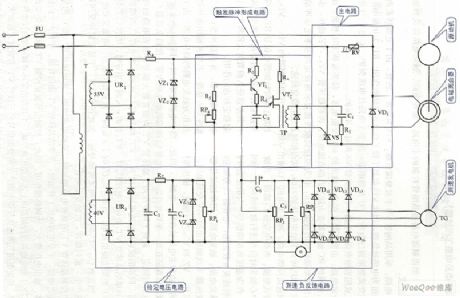
Electromagnetism speed measurement control circuit diagram (View)
View full Circuit Diagram | Comments | Reading(1285)
Piezoresistor protection transistor circuit
Published:2011/8/26 3:29:00 Author:Jessie | Keyword: piezoresistor, protection transistor
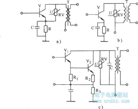
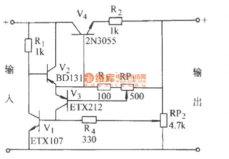
As shown in Figure a, it uses non-linear relationship of the piezoresistor to achieve the protectionfor the transistor. In Figure b, c, due to induced over-voltage suppression is below the specified value, C ~ E poles will not exceed the specified threshold voltage,so itcan play a protective role of the transistor.
(View)
View full Circuit Diagram | Comments | Reading(862)
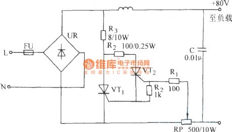
Current limiting protection circuit
Published:2011/8/26 3:26:00 Author:Jessie | Keyword: current limiting protection
View full Circuit Diagram | Comments | Reading(961)
HD-3A Energy-saving quota three-phase power supply protector
Published:2011/8/26 3:36:00 Author:Jessie | Keyword: Energy-saving, three-phase power supply
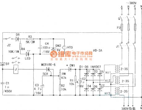
Current transformer H11-3 needs to be made by yourself. It can choose transformer core which is not less than 2W, and the secondary should be wound firstly. It uses Φ0.12mm enameled wire with around 1000 turns. Primary uses Φ1 ~ 4mm plastic wire with around 2-3 turns. It also can use finished CT. Finished current transformer has high induced voltage.
(View)
View full Circuit Diagram | Comments | Reading(1312)
Over voltage, over current protection circuit
Published:2011/8/26 3:32:00 Author:Jessie | Keyword: over voltage, over current, protection

During normal working, Tr1 and Tr2 are both disconnected, 555 resets, the discharge transistor in 555 is connected, it drains current from the base of Tr3, so that Tr3 is saturated, power 5 to 12V is directly sent to lord load. When load current exceeds prescribed value, Rsc's pressure drop increases, Tr1 is connected, 555 istriggered, internal discharge transistor stop, then Tr1 disconnected too, isolate the source and load, then 555 is monostable, reach single firm time, as long as the load flow phenomena is not ruled out, 555 will trigge again, Tr3 will still isolate load.
(View)
View full Circuit Diagram | Comments | Reading(2169)
Over current protection circuit
Published:2011/8/26 3:30:00 Author:Jessie | Keyword: over current protection
View full Circuit Diagram | Comments | Reading(3505)
The centralized controller of drainage and irrigation pumping station Two
Published:2011/8/8 21:43:00 Author:Felicity | Keyword: centralized controller, drainage and irrigation pumping station
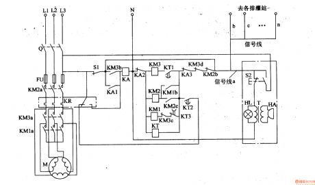
First turn Q on, and press S2 in the control room or S1 in the irrigation and drainage machine room. Then the phase voltage of L1 goes through the normally open contact of S2, signal line a, normally close contact KM2b, KM3b, KA3, KT, AKA2 to null line to make up current circuit. And KT turns on and KM1, KM2 closes in succession and the pump motor starts as Y step-down start. When it need to stop , pressing S2 or S1 again to make KA turn on, the normally open contact of KA1 close ,then the normally open contact KA2 and M3 turns off to make KM2 and KM3 release and the pump motor stops. (View)
View full Circuit Diagram | Comments | Reading(771)
irrigation motor automatic protector (2)
Published:2011/7/20 4:51:00 Author:chopper | Keyword: irrigation motor, automatic protector
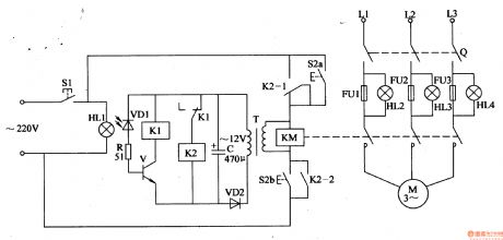
Rural irrigative pump motor often be burned due to low voltage or phase lack when it runs.This example describes the irrigation motor automatic protector, which can cut off three-phase AC power supply to protect the motor when the phase is lack. The principle of circuitThe irrigation motor automatic protection circuit is formed by the start control circuit, phase-lack control circuit and test circuit,which is shown in Figure 4-97. Start circuit is formed by the start button S2 (S2a, S2b), AC contactor KM and relay K2,etc.
(View)
View full Circuit Diagram | Comments | Reading(1074)
The centralized controller of drainage and irrigation pumping station One
Published:2011/8/8 20:33:00 Author:Felicity | Keyword: drainage and irrigation pumping station , centralized controller,
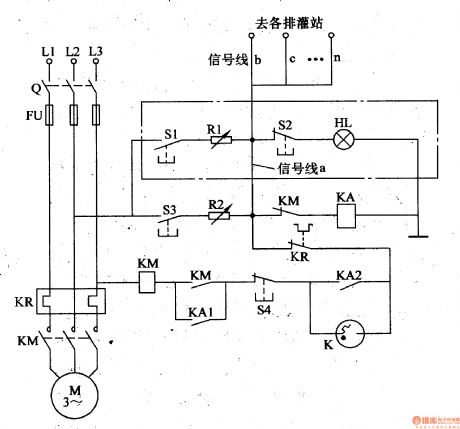
When the control room starts, the switch Q turns on. After S1 is pressed ,the phase voltage of L2 goes through S1,R1,signal line a, normally close contact of KM,KA (to null line N or ground) to make up current circuit. And KA turns on and closes, and the normally open contact KA1 switched on, the normally closed contact M2 switched off. And the phase voltage goes to phase L3 to form a circuit. After fast discharging of K, the inner contact closes to make KM turns on, and the normally open contact closes, the pump motor starting. (View)
View full Circuit Diagram | Comments | Reading(968)
Op amp output short circuit protection method circuit diagram
Published:2011/8/4 21:01:00 Author:Rebekka | Keyword: Op amp, output short circuit, protection method
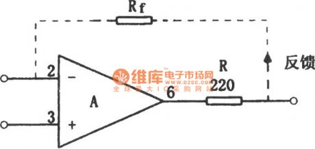
The protection method of the op amp's output short circuit is simple. It only needs to connect a small resistor R in series at the op amp output, the output short-circuit failure can be avoided. It is shown as above. If the resistor is connected to the internal feedback loop, it will have no influence on any performance but the voltage will decrease obviously(When the load is 2kΩ, the value is shown in the figure, Vo can be decreased by 10%). Another advantage of this circuit is: The circuit is also very stable for the external capacitive load. Even if the integrated operational amplifier has been added within the current limiting resistor, a small resistor should also be added at the external op amp output end. (View)
View full Circuit Diagram | Comments | Reading(3015)
The overcurrent protection of DC circuit diagram
Published:2011/8/4 20:45:00 Author:Rebekka | Keyword: DC circuit, overcurrent protection
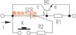
Electronic protection circuit is shown in the figure. When the micro switch K is connected to the power supply, the one-way thyristor SCR and the DC circuit will be turned on. When the power consumption excees the the allowable value, the voltage of the sense resistor R1 is greater than 0.7V, the transistor BG is turned on,the voltagebetween collector C and base b of the transistor drops belowthe sustaining voltage of 3CT. 3CT will be turned off and the power supply circuit will be cut off. Electronic protection circuit has a high-speed drying, easy recovery characteristics. It can be applied to any DC circuit for overcurrent protection equipment. (View)
View full Circuit Diagram | Comments | Reading(1661)
The battery protector with voltage charging circuit composed of 555
Published:2011/8/4 20:32:00 Author:Rebekka | Keyword: battery protector , voltage charging circuit
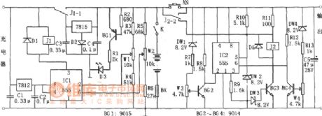
Discharge protection circuit consists of IC2 (555) and BG2, BG3, BG4 and so on. When the battery discharges to 10.5V, the regulators DW1, DW4 are regulatedto make BG2, BG4 stop. IC2 is reset becausepin ②, ⑥ are in high level; pin③ outputs low so BG3 stops. The release of relay J2 and the contact of J2-2 off (down) achieve the discharge protection. When the battery voltage is greater than 11.5V, IC2 sets, BG3 conducts, J2 pulls in, the load starts to work. When a load short circuit occurs, IC2 resets because pin ④ isin a low level. J2 releases. The short-circuit protection works. (View)
View full Circuit Diagram | Comments | Reading(839)
DC regulated power supply protection circuit composed of 555
Published:2011/8/4 20:38:00 Author:Rebekka | Keyword: DC regulated, power supply protection
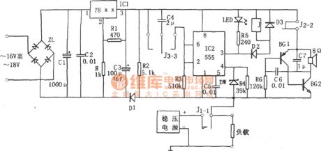
Monostable delay circuit is composed of the IC2 (555), R3, C4 and other components. Usually, J1-1 NC contact closes, the load makes IC2 ④ feet in a high potential (1V above), when the load is short circuit, 555 feet will be forced to reset because the ④ (<0.6V) level is low. ③ pin output high level to release the relay J. Contact J1-1 is connected. If it is still short circuit, it will be protected. (View)
View full Circuit Diagram | Comments | Reading(877)
Electrical equipment overload and open-phase protection device circuit composed of 555
Published:2011/8/4 20:39:00 Author:Rebekka | Keyword: Electrical equipment overload , open-phase protection device
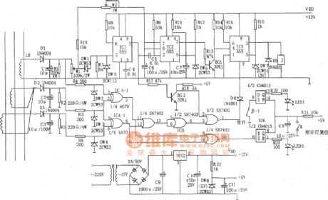
The device is composed of +12 V, +5 V DC power supply, AC transformer, voltage comparator, block timer, relay control circuit and phase loss protection circuits and other components. LH makes three-phase AC transformer current flowing couple in proportion, and they pass D1C1, D2C2, D3C3 rectifier filters and are added to the voltage comparator (IC1, DW1, DW5, R7) and phase-failure protection circuit (IC4, IC5, IC6). The phase loss protection circuit is composed of IC4 (CD4070), IC5 (7402), IC6 (CD4013). It is used for detecting and determine whether the three-phase current, if a phase-off phase, the IC3 will be set, the relay J Pick-up, the device will be cut off and the phase protection works. (View)
View full Circuit Diagram | Comments | Reading(2366)
Automatically reset earth leakage protector circuit composed of NE555
Published:2011/8/4 20:03:00 Author:Rebekka | Keyword: earth leakage protector

Signal detection circuit is the zero sequence current transformer composed of L1, L2, L3 and the magnetic core. Under normal circumstances, the total magnetic flux in the transformer is 0. When someone is shocked by the electric, the power supply passes the body to the ground, the current flowing of L1, L2 are different. Zero-sequence transformer in the magnetic flux induced in the L3 has an alternating voltage, and it is rectified by D1 and added to BG's base, so that BG saturated conduction, and 555 feet ois set because of potential ② low (<1 / 3VDo). (View)
View full Circuit Diagram | Comments | Reading(4292)
Automatic power protector circuit composed of 555
Published:2011/8/4 20:03:00 Author:Rebekka | Keyword: Automatic power protector, 555
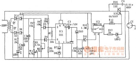
The figure shows the automatic power protection circuit. The protector is composed of the buck rectifier circuit, overvoltage and undervoltage detection circuit, delay switch control circuit. The buck rectifier circuit provides DC voltage for the entire circuit. (View)
View full Circuit Diagram | Comments | Reading(918)
Automotive electronic password lock circuit diagram
Published:2011/8/4 21:35:00 Author:Rebekka | Keyword: Automotive electronic password lock
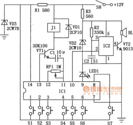
Automotive electronic code lock circuit is shown as above. ICl is exclusive lock for the integrated circuit 5G058, its ① ~ ⑥ feet connect external key switch to the power supply. They are six valid input keys. The unlock must follow the sequence of Sl ~ S6; pin ⑧ button switch S7 is connected to the false key input. It is free to pick one or a few keys on the keyboard plugged in as real mixed; pin⑨ is the key indication side, each key will cause the external connectivity in the light-emitting diode LEDl. (View)
View full Circuit Diagram | Comments | Reading(2542)
Multi-function household electrical appliances protection circuit diagram
Published:2011/8/4 21:34:00 Author:Rebekka | Keyword: household electrical appliances, protection circuit
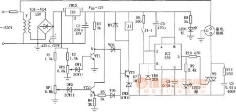
The circuit is composed of DC circuit, delay circuit, overvoltage and undervoltage protection circuit etc. ICl integrated circuit LM7812 outputs +12 V voltage. Undervoltage and overvoltage sample protection circuit is composed of sampling R2, potentiometer RP2, the regulator DWl, VTl and Rl, RPl, DW2, VT2, VD5, VD6, VT3 and control relay J1. In the figure, VT1 ~ VT3 use 3DG4, thyristor VS uses 6A/400V, VD1 ~ VD7 use 1N4004, relay J1 uses JRC-1M 12V.
(View)
View full Circuit Diagram | Comments | Reading(2502)
CROWBAR
Published:2009/7/14 5:32:00 Author:May
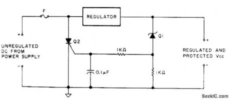
When output of regulator for microprocessor power supply exceeds maximum safe voltage as determined by zener Q1, SCR Q2 is triggered on and conducts heavily, blowing fuse rapidly to protect equipment. Fuse rating is 125% of nominal load. Choose SCR to meet voltage and current requirements. Choose zener for desired trip voltage. Each germanium diode in series with Q1 will add 0.3 V to trip voltage, and silicon diodes add 0.6 V. To calibrate, place 1K resistor temporarily in series with Q2 and measure drop across it to see if SCR fires and produces surge on meter at desired VCC.-J. Starr, Want to Buy a Little Insurance? , Kilobaud, 0ct. 1978, p 89. (View)
View full Circuit Diagram | Comments | Reading(0)
TRANSISIOR_OVERLOAD_PROTECTION
Published:2009/7/14 5:24:00 Author:May
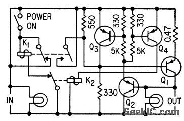
Current greater than 3 amp flowing through 0.47-ohm resistor in emitter of current-switching transistor Q1 drops voltage on base of Q2, causing Q2, Q3, and Q4 to saturate. Q3 opens circuit immediately and keeps it open for duration of overload, For complete short-circuits, Q4 latches K2 to provide positive protection.-F. W. Kear, Fast-Response Over-loud Protection, Electronics, 33:7, p125. (View)
View full Circuit Diagram | Comments | Reading(770)
| Pages:3/12 123456789101112 |
Circuit Categories
power supply circuit
Amplifier Circuit
Basic Circuit
LED and Light Circuit
Sensor Circuit
Signal Processing
Electrical Equipment Circuit
Control Circuit
Remote Control Circuit
A/D-D/A Converter Circuit
Audio Circuit
Measuring and Test Circuit
Communication Circuit
Computer-Related Circuit
555 Circuit
Automotive Circuit
Repairing Circuit