
Protection Circuit
Index 6
IC_REGULATOR_PROTECTION
Published:2009/6/23 3:55:00 Author:May
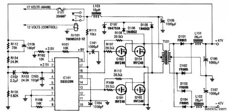
This circuit protects an IC regulator against various fault conditions. (View)
View full Circuit Diagram | Comments | Reading(0)
MC33035 over-current protection circuit diagram
Published:2011/7/28 21:32:00 Author:Ecco | Keyword: over-current protection circuit
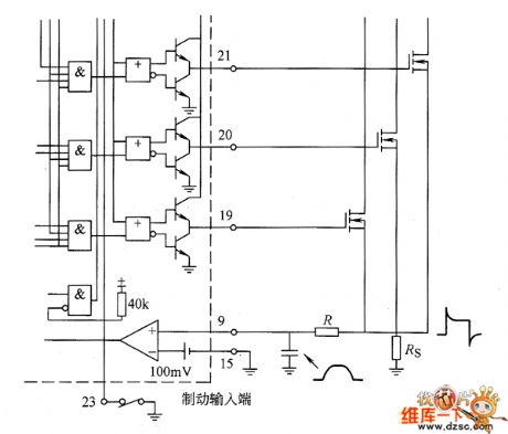
MC33035 overcurrent protection circuit is shown as the chart. MC33035 uses the external inverter to be grounded by resistor RS for the current sampling. Sampling voltage is input to the current sense comparator by pin 9 and pin 15. Inverting input of the comparator (pin 15) is set a 100mV reference voltage, which is used as the current limit ing benchmark. In the oscillator sawtooth rising time, if the current is too large, the comparator will flip so that the next RS flip-flop resets and closes the driven output to limit the current from continuing increase.
(View)
View full Circuit Diagram | Comments | Reading(1600)
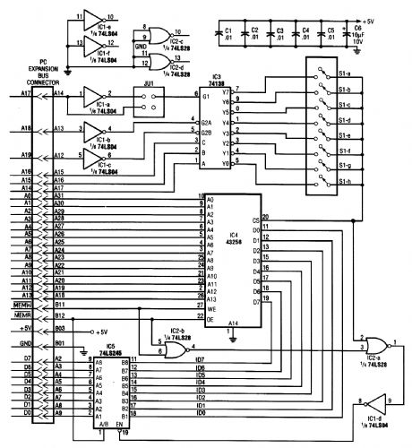
PG_PASSWORD_PROTECTOR
Published:2009/6/22 23:01:00 Author:May
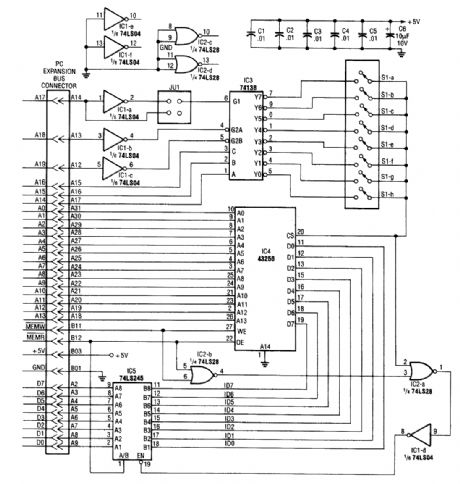
IC4, a static RAM, is mounted in a smart built-in switch over circuitry. This retains SRAM con-tents when power is off. The rest of the circuitry consists of address decoding logic and jumper JU1, used to decode a 16K address space for the 32K static RAM. Software is necessary and this is con-tained in the original article (see reference). (View)
View full Circuit Diagram | Comments | Reading(0)
Op amp common-mode voltage breakdown input stage and its protection measure circuit diagram
Published:2011/5/17 2:45:00 Author:Rebekka | Keyword: Op amp , common-mode voltage, breakdown input stage, protection measure
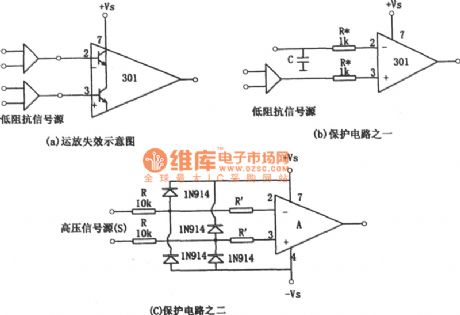
There is a current of the transistor collector junction flow from basal pole to collecting anode. If the source of resistance passes from feet 2 or feet ③ is low, then the collector junction current will be very large, and the input stage transistors will be damaged. In this case, remove the power supply voltage, and the signal source is not removed. The common-mode input will damage the ntegrated operational amplifier. Another case that makes the integrated operational amplifier common mode input failure is that the signal source has capacitive elements. The capacitance is charged to the high level of the signal source, remove the supply voltage and signal at the same time. Because the existance of charging voltage of the signal source capacitance, it is equivalent to the existance of signal source voltage. If the capacitor is greater than 0.1μF. The discharge current of the capacitor can burn the transistor. (View)
View full Circuit Diagram | Comments | Reading(1119)
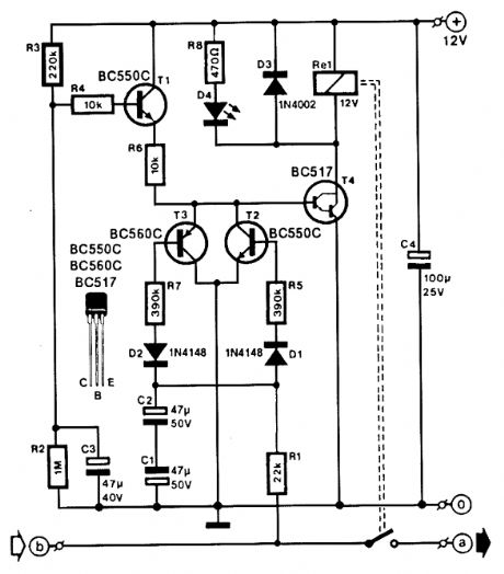
Multi-purpose household protection circuit composed of the C036
Published:2011/6/24 3:23:00 Author:Rebekka | Keyword: Multi-purpose household protection
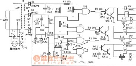
Delayed protection circuit is mainly composed of the charge and discharge loop (R6, C5), YF1 and the RS flip-flop, relay J3, driver circuit (BG2, BG3) composed of YF2. When it is connected with the power supply, because the voltage on C5 is not mutation, YF1 outputs low. It makes BG2, BG3 conducted, the relay J3 will be pulled in. The load starts to work because the J3-1 is connected to the power supply. (View)
View full Circuit Diagram | Comments | Reading(710)
Small non-contact refrigerator time delay protector circuit diagram
Published:2011/5/15 6:03:00 Author:Rebekka | Keyword: Small non-contact refrigerator, time delay protector
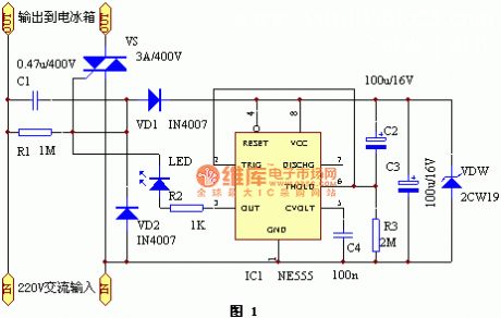
The protector circuit is shown in the figure 1. 220V AC power passes the capacitor C1 buck, VD1 half-wave rectifier to the regulated VDW the time base circuit 555 as a working power supply. When it connects to power supply for about 5 minutes, the time base circuit ③ foot outputs from low to a high level. The two-way thyristor VS will be conducted to work and provides power supply for the refrigerator. At this time the light-emitting diode LED is lit. It indicates the power supply is normal. (View)
View full Circuit Diagram | Comments | Reading(2682)
BATTERY_PACK_AND_REVERSE_POLARITY_PROTECTION
Published:2009/6/18 3:03:00 Author:May
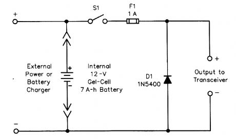
Schematic diagram and parts list for the reverse-polarity protection circuit D1 1N5400 silicon diodeF1 1-A fast-acting fuseS1 SPST rocker switch (View)
View full Circuit Diagram | Comments | Reading(2278)
SIMPLE_SAFETY_CIRCUIT
Published:2009/6/17 21:05:00 Author:May
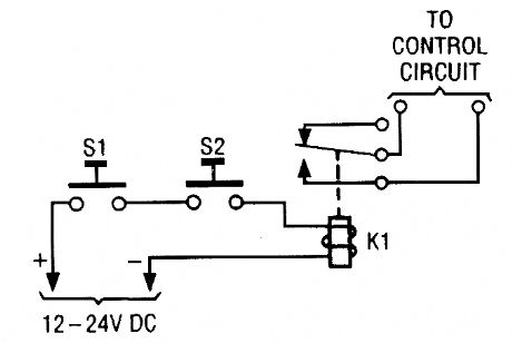
The simple two-hand safety-control switch shown here is little more than two pushbutton switches connected in series; both must be de-pressed in order to energize the relay. (View)
View full Circuit Diagram | Comments | Reading(1072)
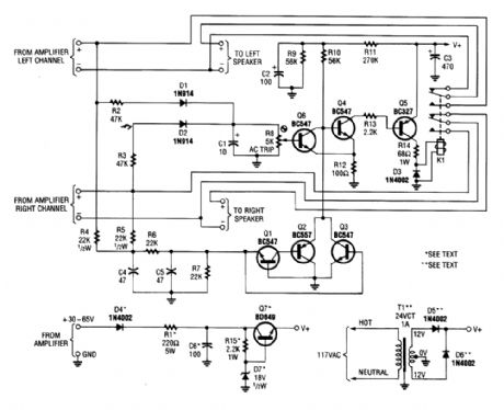
LOUDSPEAKER_PROTECTOR
Published:2009/6/17 21:04:00 Author:May
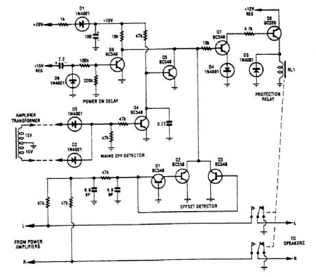
Transistors Q1, Q2, and Q3 monitor the two outputs of the stereo amplifier. If the offsets exceed ±2 V, Q7 is turned off, which turns off Q8 and the normally on relay. Diodes D2 and D5, together vith Q4, provide a mains voltage monitor. As soon as the ac input voltage disappears, as when the ampli-fier is turned off, Q4 turns off and Q5 turns on. This turns off Q7, Q8, and the relay. Hence, the loud-speakers are disconnected immediately after the amplifier is turned off. (View)
View full Circuit Diagram | Comments | Reading(920)
EAR_PROTECTOR
Published:2009/6/17 21:02:00 Author:May
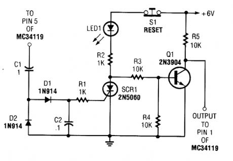
The ear protector is actually a peak audio- detector/shutdown circuit that disables the amplifier through its chip-disable input when the output volume of an amplifier reaches the set level. The cir-cuit, although intended for the MC34119 amplifier, should work with similar IC devices or applications. (View)
View full Circuit Diagram | Comments | Reading(871)
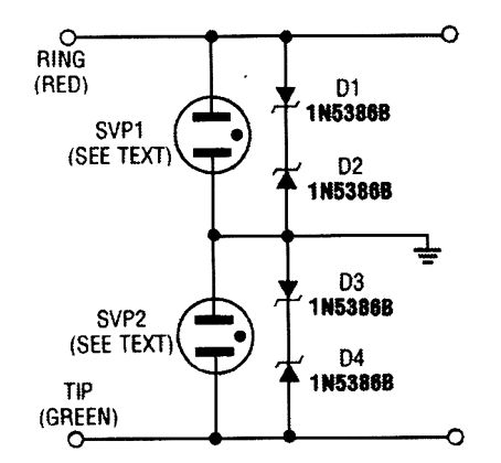
MODEM_FAX_PROTECTOR_FOR_TWO_COMPUTERS
Published:2009/6/17 21:01:00 Author:May
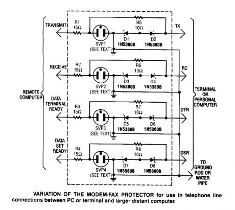
This modem/fax protector can be used in telephone-line connections betweenaPC or a terminal and a distant computer. In this circuit, the SVPs (surge voltage protectors) are at 230V.A good ground is a must for effective operation. (View)
View full Circuit Diagram | Comments | Reading(1226)
OVERVOLTAGE_PROTECTION_CIRCUIT
Published:2009/6/17 20:55:00 Author:May
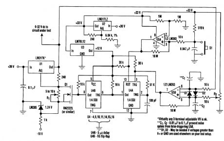
When testing a circuit, a source of voltage that is variable and has overvoltage shutdown is very useful. In this circuit, R1 is adjusted to 1 to 2 V below the eventual shutdown threshold. R2 sets the trip voltage. When this voltage is reached, the circuit shuts the voltage to the circuit under test down. To reset, reduce R1 below trip threshold and depress reset switch S1. (View)
View full Circuit Diagram | Comments | Reading(404)
MODEM_PROTECTOR
Published:2009/6/17 20:51:00 Author:May
This protector uses surge voltage protectors rated at 230-V breakdown. An effective ground should be used. (View)
View full Circuit Diagram | Comments | Reading(1058)
SPEAKER_PROTECTOR
Published:2009/6/17 20:36:00 Author:May
Most of the transistors in this speaker protector function as switches. Normally, Q4, Q5, and K1 are on and the speakers are connected to the amplifier. However, if a large dc voltage appears at an amplifier output, either Q3, or Q1 and Q2 turn on; biasing Q4 off. That action turns Q5 off, de-ener-gizes the relay, and disconnects the speakers from the amplifier. Components D1, D2, and Q6 form the overdrive-protection circuit. (View)
View full Circuit Diagram | Comments | Reading(4309)
PC_PASSWORD_PROTECTION
Published:2009/6/17 3:12:00 Author:May
With this circuit, a PC will be protected, requiring a password to boot. After three times, the computer will have to have a cold reboot and the password tried again. Software for this system is available-consult the reference for further details. (View)
View full Circuit Diagram | Comments | Reading(1122)
HALOGEN_LAMP_PROTECTOR
Published:2009/6/17 2:17:00 Author:May
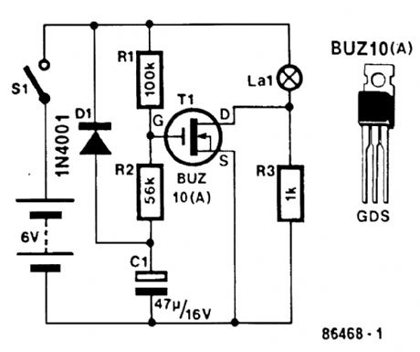
This circuit produces a soft turn-on for halogen lamp filaments upon powerlng up,MOSFETRI used is a BUZ10, which has 0.2Ω RDS on.R1,R2,and C1 set the turn-on rate and D1 discharges C1 at turn-off. (View)
View full Circuit Diagram | Comments | Reading(1083)
Variable threshold over-current and over voltage protection circuit diagram
Published:2011/5/12 21:47:00 Author:Rebekka | Keyword: Over-current protection, over voltage protection
The circuit will set the corresponding reference threshold for effective protection of the load depending on the actual voltage and current of the load. The whole circuit is composed of over current, over voltage detection, signal amplifier and control signal output circuit, manual start, stop control circuit and thyristor trigger circuit. (View)
View full Circuit Diagram | Comments | Reading(1550)
Monolithic over and under voltage protection circuit diagram
Published:2011/5/12 21:34:00 Author:Rebekka | Keyword: Monolithic over and under voltage protection
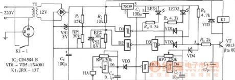
The over and under voltage protection circuit is composed of the six Schmitt trigger CD4584 . When it is over-voltage or under voltage. The circuit will sound siren and cut off the working power supply of the controlled circuit by relay. (View)
View full Circuit Diagram | Comments | Reading(2871)
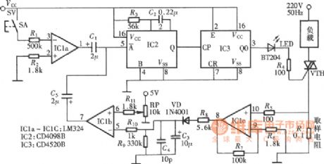
Cable radio and amplifier protector circuit diagram
Published:2011/5/16 4:07:00 Author:Rebekka | Keyword: Cable radio , amplifier protector
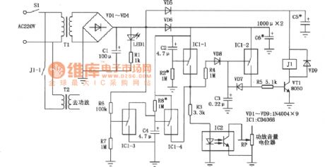
The high-power amplifiers radio used in the broadcast room of cable radio towns in rural areas is easily damaged. The reasons are: The frequent use, non-service management, the radio is often shut down when it works in the maximum volume state or the radio is started in the whole input power. This kind of amplifiers radio is arge output transformer output. There are are many transformers in the circuit. The peak inverse voltage maybe breakdown amplifier tube when you turn on or turn off the machine. The peak inverse voltage is caused by improper operation. The circuit can turn off the signal before the amplifier start to work. And it can also turn down the volume before the machine is turned off. So that the amplifier can be protected from damage. (View)
View full Circuit Diagram | Comments | Reading(724)
United reaper full warehouse reminder (2)
Published:2011/7/19 23:16:00 Author:chopper | Keyword: United reaper, full warehouse reminder
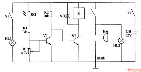
The principle of circuitThis united reaper full warehouse reminder circuit is formed by the photoelectric detection amplification circuit and the sound and light alarm circuit,which is shown in Figure 4-99.The photoelectric detection amplification circuit is formed by the indicator light HL1,light switche S1,photosensitive resistor and transistor V1. The sound and light alarm circuit consists of transistor V2, the relay K, the diode VD, indicator light HL2 and buzzer HA.
(View)
View full Circuit Diagram | Comments | Reading(686)
| Pages:6/12 123456789101112 |
Circuit Categories
power supply circuit
Amplifier Circuit
Basic Circuit
LED and Light Circuit
Sensor Circuit
Signal Processing
Electrical Equipment Circuit
Control Circuit
Remote Control Circuit
A/D-D/A Converter Circuit
Audio Circuit
Measuring and Test Circuit
Communication Circuit
Computer-Related Circuit
555 Circuit
Automotive Circuit
Repairing Circuit