
LED and Light Circuit
Index 67
using RCM-1A/1B wireless remote control spotlight circuit
Published:2011/5/17 9:36:00 Author:Lena | Keyword: wireless, remote control, spotlight

(View)
View full Circuit Diagram | Comments | Reading(607)
BA656-the integrated circuit of LED potential indicating driver
Published:2011/5/17 5:38:00 Author:Borg | Keyword: integrated circuit, LED
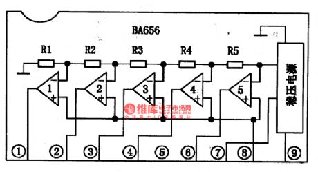
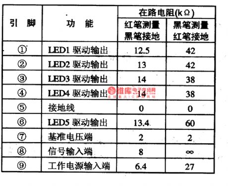
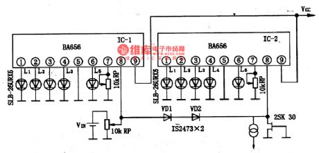
BA656 is an integrated circuit of LED potential indicating drive Toyo Power Tool Corp., Japan, which is used in simple instrument, voltage detection and demodulation circuits.1.the internal circuit and pin functions of BA656BA656 can directly drive 5 LED. This kind of potential indicating driver has 5 comparison circuits each level. It is in single 9-lead in-line package, whose internal circuit is shown in Figure 1, and its pin functions and data are listed in Table 1.
Figure1 the internal circuit of BA656
(View)
View full Circuit Diagram | Comments | Reading(3675)
500kHs bandwidth photoelectric isolating circuit diagram composed of A-840V/F reversal module
Published:2011/5/17 1:47:00 Author:Ecco | Keyword: 500kHs , bandwidth, photoelectric isolating, reversal module
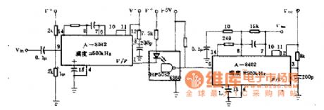
This circuit uses the A-8402V / F converter components, the linear is ± 0.05%, the maximum switching frequency is higher than 500KHZ to drive light emitting diode of optical isolator. The other A-8402V / F component can change the output of the optical isolator into a proportional DC voltage. The power supply is 12V or 5 ~ 18V. The A-840V / F components shown as the chart can form a 500kHs bandwidth optical isolation circuit.
(View)
View full Circuit Diagram | Comments | Reading(604)
Beijing Wuzhou elevator lighting circuit
Published:2011/5/12 20:05:00 Author:TaoXi | Keyword: Beijing, Wuzhou elevator, lighting circuit
Beijing Wuzhou elevator lighting circuit (View)
View full Circuit Diagram | Comments | Reading(556)
Dynamic display circuit diagram of parallel LED digital tube (common anode)
Published:2011/5/12 2:28:00 Author:Ecco | Keyword: dynamic display, parallel, LED, digital tube
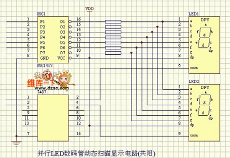
Parallel LED digital tube diaplay circuit diagram is as below:
(View)
View full Circuit Diagram | Comments | Reading(1016)
LED flashing circuit diagram
Published:2011/5/10 21:47:00 Author:Ecco | Keyword: LED flashing
LED flashing circuit diagram is shown as the chart.
(View)
View full Circuit Diagram | Comments | Reading(1270)
Charge Pump And Inductor LED Driver Circuit
Published:2011/5/10 7:47:00 Author:Robert | Keyword: Charge Pump, Inductor, LED, Driver
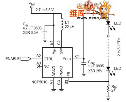
The Charge Pump And Inductor LED Driver Circuit is shown below.
(View)
View full Circuit Diagram | Comments | Reading(1741)
LED luminescence circuit diagram
Published:2011/5/9 3:30:00 Author:Nicole | Keyword: LED, luminescence
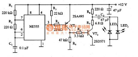
The figure1 is a LED luminescence circuit. This circuit is widely used in factory's automatic production line, as optical switch, it can measure whether has block objects pass though. In the circuit, NE555 produces pulse current with small duty ratio, it can make LED shine. When VT2 cuts off, it charges, when VT1 turns on, it dischanges, then LED can obtain larger current. Because it adopts pulse luminescence mode, so it can reduce power consumption.
(View)
View full Circuit Diagram | Comments | Reading(712)
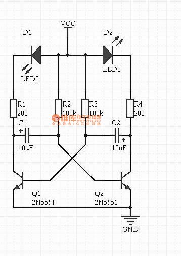
A Small-Scale Photoflash Circuit
Published:2011/5/7 19:58:00 Author:Borg | Keyword: Small-Scale, Photoflash Circuit
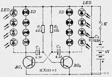
The following is a small-scale photoflash circuit, when it works, the two teams of micro bulbs will flash alternately.
(View)
View full Circuit Diagram | Comments | Reading(629)
Two-color LED internal circuit diagram
Published:2011/5/5 7:53:00 Author:Rebekka | Keyword: Two-color LED internal circuit
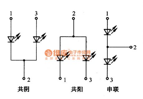
LED is small, cheap, long life, high reliability. It is often used in power-off state display and monitoring circuit. The most convenient two-color LED. The face of it looks like an ordinary LED, but it has three pins. Two-color LED's internal circuit is shown as below. The two LED are connected. There are common cathode, common anode and series because of different connection. (View)
View full Circuit Diagram | Comments | Reading(2317)
Christmas lights circuit diagram
Published:2011/5/5 4:13:00 Author:Ecco | Keyword: Christmas light
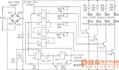
The chart shows the Christmas lights circuit composed of simple, inexpensive CD4069 six-inverter, it can control 4 loops with 200 light-emitting diodes (50 per channel), and they are directly driven by the 220V power supply and does not need power transformer. Ater the power supply rectified by VD1 ~ VD4 bridge, it is filtered by the partial pressure on R1, R5 and C1, the two ends of the C1 will get a DC voltage with about 6V for IC1 (CD4069). D5 and D6 form gate low-frequency oscillation. The frequency is adjusted by RP. Its output passing a combination shaping by D1 ~ D4 could control the four transistors with high back pressure (2N3440/2N3439) VT1 ~ VT4. The per channel of VT1 ~ VT4 uses 50 LEDs as Illumination load. RP2 ~ RP5 are used to adjust the VT1 ~ VT4 to adapt to different working conditions of the lantern load.
(View)
View full Circuit Diagram | Comments | Reading(3264)
5-point LED display driver circuit diagram composed of HA7666P/TA7667P
Published:2011/5/5 4:28:00 Author:Ecco | Keyword: 5-point , LED , display, driver
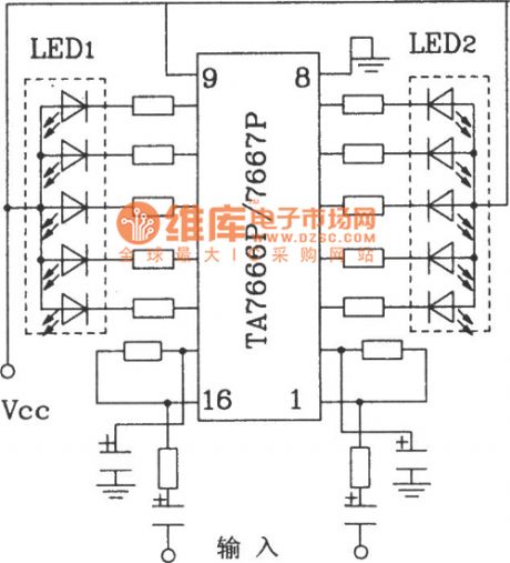
5-point LED display driver circuit diagram composed of HA7666P/TA7667P
This circuit is an analog voltage input signal input, to display according to scale. A 10-point display model is TLR8101 or TLG8101.
(View)
View full Circuit Diagram | Comments | Reading(1470)
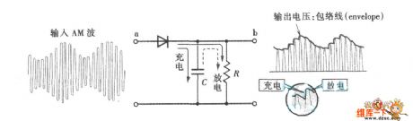
diode demodulation circuit diagram
Published:2011/5/4 9:46:00 Author: | Keyword: diode, demodulation, circuit
View full Circuit Diagram | Comments | Reading(701)
LED Open-circuit Protective Circuit
Published:2011/5/3 8:34:00 Author:Joyce | Keyword: LED, Open-circuit, Protective, CP2126
As you can see,italmost has no impact on the receiving sensitivity of mobile phones that whether CP2126 works or not .But if the chip X is at work,the receiving sensitivity would decrease because of the interference caused by EMI . Meanwhile, under the typical condition that CP2126 with a voltage input of 3.6 V drives three white light LED, the conversion efficiency can reach 83% .
The design of PCB will also have a great influence on the performance of the circuit. Generally, routings on the part of high frequency should be as short and thick as possible,vias to the ground should be as lagre and abundant aspossible to meet the requirements claimed in the relevant information of CP2126 .
In application, LED may happen to have some open fault.In this case, because the feedback voltage of pin CS will keep at 0, so if there is no protective circuit, this kind of boost circuit will boost till the switching tube within gets punctured and breaks down.Therefore, chips without the protection of built-in protective circuit need to add a Zener diode to protect the internal switching tube. The LED open-circuit protection circuit is shown in the graph.It is obvious that such protective circuit will increase the cost of the system and the acreage of PCB . Another method to protect the circuit is to add a pin, use capsulation like SOT23-6L,and sample and detect the voltage of UOUT. Because CP2126 has a built-in output open-circuit protective circuit, it can ensure that the chip would not be damaged in the circumstance that no change has to be done to the peripheral application circuit and LED is open.When malfunction is removed, thechipcan again work properly. (View)
View full Circuit Diagram | Comments | Reading(818)
Beijing Cherokee light off-road vehicles instrument panel lighting wiring circuit diagram
Published:2011/5/4 2:49:00 Author:Rebekka | Keyword: Beijing Cherokee, light off-road vehicles
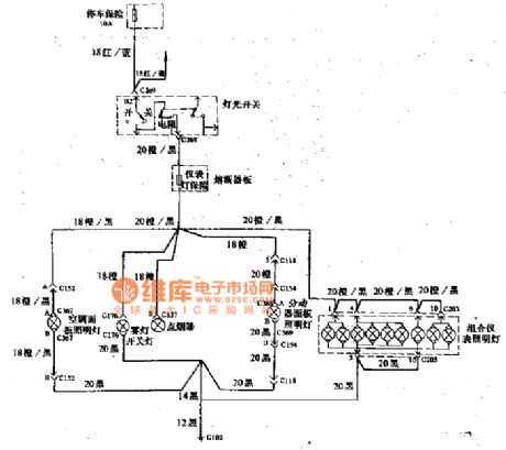
Beijing Cherokee light off-road vehicles instrument panel lighting wiring circuit diagram. (View)
View full Circuit Diagram | Comments | Reading(727)
Practical two-color LED circuit diagram
Published:2011/5/4 2:46:00 Author:Rebekka | Keyword: Practical two-color LED
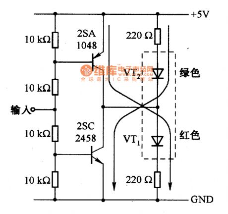
The actual circuit of using two-color LED display is shown as above. When input +5 V, VT1 turns on, green LED light; Input is 0, VT2 turns on, red LED light. (View)
View full Circuit Diagram | Comments | Reading(1030)
Industrial and mining field indicator light circuit
Published:2011/5/2 7:51:00 Author:Nicole | Keyword: industrial and mining field, indicator light
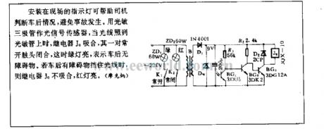
The indicator lights are fixed in the field that can help driver tojudge the situation behind car, to prevent accidents. Using phototransistor as singal sensor, when the light fell on photosensitive tube, relay J0 pulls in, a pair of often opening contacts are closed, then the green light is on, it means that there is no obstruction behind car. If there is obstruction to keep out light, then relay J0 dose not pull in, the red lights on. (View)
View full Circuit Diagram | Comments | Reading(731)
Shenyang SANYO AC double speed elevator lighting circuit
Published:2011/4/29 4:29:00 Author:Nicole | Keyword: SANYO, double speed stair
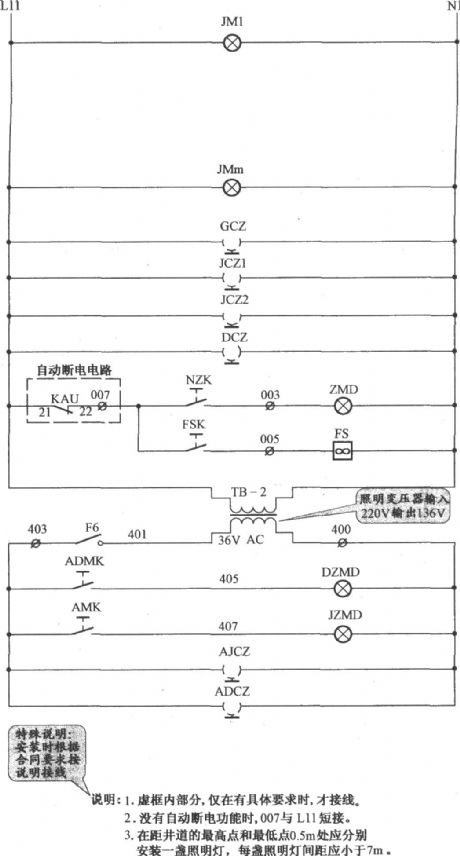
Explanation: 1. The part in gridlines is connected when it has specific requirements. 2. If there is no automatical power off function, 007 is short-circuit to L11. 3. fixing a light on theplace which is 0.5m away from the highest point and the lowest point of the shaft, the space between each light should beshorter than 7m. (View)
View full Circuit Diagram | Comments | Reading(742)
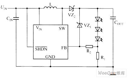
Drive White Light LED Circuit
Published:2011/4/26 Author:Joyce | Keyword: Drive, White Light, LED
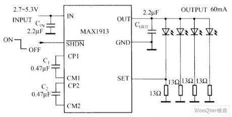
Input voltage of MAX1913 ranges from 2.7V to 5.3 V. it could provide stable output voltage or output current to drive the white light LED. As shown in the graph is a MAX1913 Drive White Light LED circuit . It needs only four small ceramic capacitors to fully compose DC/DC regulator without inductance. Its unique design of charge pump can decrease the input ripple and maintain a stable 750kHz switching frequency in a wide load range. MAX1913 also includes logic level turnoff and soft start function to decrease insurge current when activated.The main features are as follows.
(1) low input ripple, 750kHz working frequency.(2) current detection threshold of 200mV to reduce power consumption.(3) 60mA output current . 3% adjustable range of output compact.(4) 1μA shutoff current.(5) minute pin encapsulation . (View)
View full Circuit Diagram | Comments | Reading(775)
Power Outage Lighting Circuit With Charging Protection
Published:2011/5/2 2:49:00 Author:Robert | Keyword: Power Outage, Lighting, Charging Protection
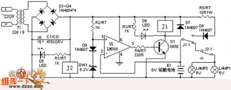

When the power grids have electricity, the comparator U1's + side is referenced voltage 6.9V, if the battery voltage become lower, the u1 would output high voltage level, q1 become conducted, j1 is connected, the battery begin to charging; when the battery voltage rise to the voltage of referenced voltage 6.9V or more, u1 would output low voltage level, which make j1 lost electricity and become disconnected, this achieve auto-charging and protection function. Because of the J2 makes the lamp disconnected, so lamp doesn't light. When the power grids have outage, j1,j2 are all losting electricity and becoming disconnected, so the lamp light.
(View)
View full Circuit Diagram | Comments | Reading(818)
| Pages:67/72 At 20616263646566676869707172 |
Circuit Categories
power supply circuit
Amplifier Circuit
Basic Circuit
LED and Light Circuit
Sensor Circuit
Signal Processing
Electrical Equipment Circuit
Control Circuit
Remote Control Circuit
A/D-D/A Converter Circuit
Audio Circuit
Measuring and Test Circuit
Communication Circuit
Computer-Related Circuit
555 Circuit
Automotive Circuit
Repairing Circuit