
LED and Light Circuit
Index 70
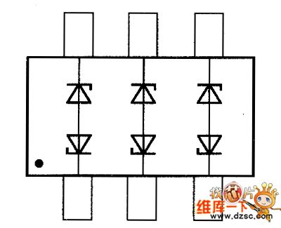
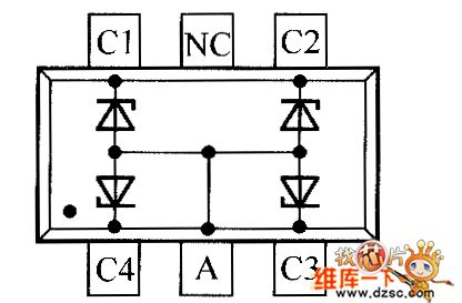
Crystal diode STTH60L06TV2 and STTH6110TV2 internal circuit diagram
Published:2011/4/12 22:55:00 Author:Rebekka | Keyword: Crystal diode
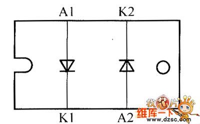
Crystal diode STTH60L06TV2 and STTH6110TV2 internal circuit diagram is shown as above. (View)
View full Circuit Diagram | Comments | Reading(636)
Simple silicon-controlled dimmer circuit diagram
Published:2011/4/5 21:46:00 Author:Ecco | Keyword: Simple silicon-controlled , dimmer
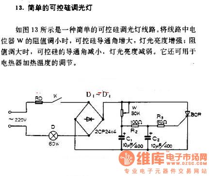
Simple silicon-controlled dimmer
As shown in Figure 13, it is a simple circuit of SCR dimming lights. The w resistance in the potentiometer decreases, SCR conduction angle increases, the light's intensity increases, the resistance enlarges, the SCR conduction angle decreases, the light's intensity decreased. It can also be used as adjusting the heating temperature.
(View)
View full Circuit Diagram | Comments | Reading(3030)
Simple music control lights circuit diagram
Published:2011/4/5 21:17:00 Author:Ecco | Keyword: Simple music , control light
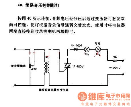
Simple music control lights circuit
It connects according to the chart 40, The audio voltage with the partial pressure can trigger bidirectional triode thyristor by transformer, the strength of the lamp changes alternately according to the music signal light, when using, the potentiometer can be connected directly to the tape recorder speaker at both ends.
(View)
View full Circuit Diagram | Comments | Reading(1453)
Two 110-volt light bulbs connected to the 220-volt power supply circuit
Published:2011/4/6 1:47:00 Author:Ecco | Keyword: 110-volt light bulb, 220-volt power supply
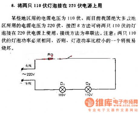
Two 110-volt light bulbs connected to the 220-volt power
The power supply in some areas is 110V while the majority of the power supply in majority of areas is 220V, as shown in Figure 8, two 110V bulbs can be connected to the 220V power supply in series connection. Note: The power of two 110V lamps must be the same, otherwise, the smaller power bulb will be burnt earsily.
(View)
View full Circuit Diagram | Comments | Reading(2148)
The fluorescent with reactive power compensation circuit diagram
Published:2011/4/6 2:20:00 Author:Ecco | Keyword: fluorescent , reactive power compensation
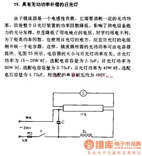
The fluorescent with reactive power compensation
As ballast is an inductive load. It needs to consume some reactive power, causing the power factor of fluorescent lamp decreases. It affects the ability of full-powered devices, and reduces the voltage of power stations, and it's harmful to saving electricity. In order to improve power factor, where the using of fluorescent lamps, fluorescent lamp power supply side should be parallel connected a capacitor, so that the ballast's reactive power can be provided by capacitor. Figure 25 shows. The size of capacitor and fluorescent power is related. Fluorescent power is 15 ~ 20W, matching capacitance is 2.5μF; fluorescent power is 30w, the optional capacitance is 3.75μF; fluorescent power is 40w, the optional capacitance is 4.75μF. The optional capacitor voltage are 400V.
(View)
View full Circuit Diagram | Comments | Reading(1757)
LED voltage measurement circuit
Published:2011/4/7 1:36:00 Author:Nicole | Keyword: LED, voltage measurement
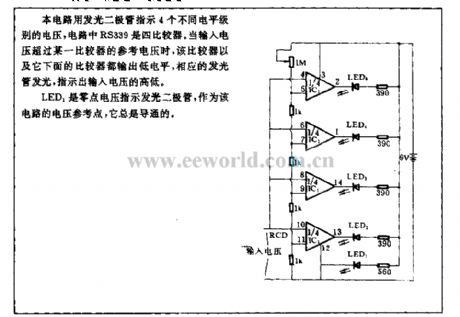
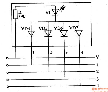
This circuit uses LED to indicate four different level class voltage, the RS339 is four comparators. When the input voltage is outstripping one comparator's reference voltage, then this comparator and the other comparators below it are all output low level, the relevant LED is lightening, indicated the high and low of input voltage.
As voltage reference point, LED1 is zero point voltage indication LED, and it is always conduction. (View)
View full Circuit Diagram | Comments | Reading(912)
Two double switch controlling two lamps in two different places
Published:2011/4/7 3:31:00 Author:Ecco | Keyword: Two double switch, controlling two lamps , in two different places
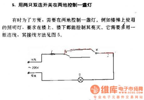
Two double switch controlling a lamp in two different places
Sometimes, it's convenient to control a lamp in two different places. For example, the lamp used above the stairs is required to be turned on and off both on the upstairs and downstairs. It requires a multi-connection, the connection method shown in Figure 5.
(View)
View full Circuit Diagram | Comments | Reading(1091)
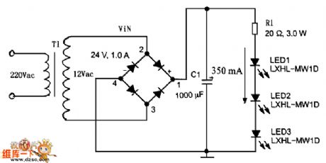
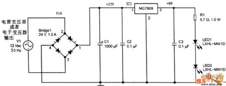
High current LED drive circuit diagram with AC power supply
Published:2011/4/1 3:33:00 Author:Nicole | Keyword: high current LED drive, AC power supply
View full Circuit Diagram | Comments | Reading(2426)
LED drive circuit diagram with linear regulator
Published:2011/4/1 3:33:00 Author:Nicole | Keyword: LED drive
View full Circuit Diagram | Comments | Reading(735)
Transistor BUB323Z internal circuit diagram
Published:2011/4/11 1:40:00 Author:Rebekka | Keyword: Transistor, internal circuit
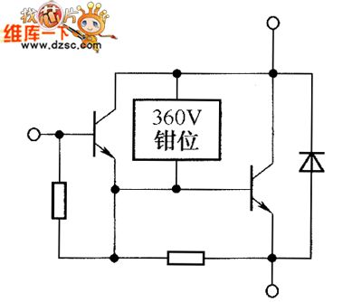
Transistor BUB323Z internal circuit diagram is shown as below.
(View)
View full Circuit Diagram | Comments | Reading(664)
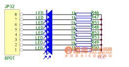
The simplest eight rolling subtitles circuit diagram
Published:2011/4/2 3:55:00 Author:Rebekka | Keyword: eight rolling subtitles
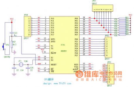
Delay subroutine, clr, lcall, ajmp instruction are mainly used in the experiment. Through lighting p1.0 …..P1.7 by turns to achieve the results. The user can preliminary master the IO port operation of SCM by this study of program.
Reference program:
Experiment 1 the simplest eight rolling subtitles. Conect the P1 port of CPU(JP44) with JP32 part of the Eight light by a data cable 8PIN; You will see 8 lights flashingalternately.
org 0000h; Start ajmp loop org 0030h; To avoid the sensitive address of 00-30 at 0030h loop:mov p1,#0ffh; Turn off all the lights. clr p1.0; Turn on light p1.0lcall delay; To delay for a whole? clr p1.1; Turn on light p1.1 lcall delay clr p1.2; Turn on light p1.2 lcall delay clr p1.3; Turn on light p1.3 lcall delay clr p1.4; Turn on light p1.4 lcall delay clr p1.5; Turn on light p1.5 lcall delay clr p1.6; Turn on light p1.6 lcall delay clr p1.7; Turn on light p1.7 lcall delay AJMP LOOP; To re-run at the beginning of loop delay: mov r5,#20; Delay. d1: mov r6,#40 d2: mov r7,#248 djnz r7,$ djnz r6,d2 djnz r5,d1 ret end (View)
View full Circuit Diagram | Comments | Reading(646)
General connection method of fluorescent lamp circuit diagram
Published:2011/4/7 2:04:00 Author:Ecco | Keyword: General connection method , fluorescent lamp
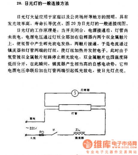
General connection method of fluorescent lamp
Fluorescent lamps used in homes and public places lighting and so on, with luminous efficiency, long service life, Figure 20 is the general wiring diagram for lamp.
Fluorescent working principle: When the switch is closed, power is on, the lamp doesn't start to discharge , power supply voltage is added to two metal contacts of the starter through the filament, then the neon tube produces glow discharge and heat, the two contacts are connected, so the current through the ballast and the filament at both ends of the tube, the filament heating and emits electrons. At this time, the neon tubes are short cut by metal contacts and stop producing glow discharge, two metal contacts are separated by temperature declining. At this moment, the ballast will produce high induced electromotive force, which is added to the supply voltage in series and causes producing glow discharge at both ends of the lamp, so fluorescent is lit.
(View)
View full Circuit Diagram | Comments | Reading(2880)
Using diode to extend life of incandescent lamp circuit diagram
Published:2011/4/7 2:40:00 Author:Ecco | Keyword: diode , extend life , incandescent lamp
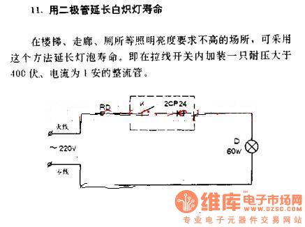
Using diode to extend life of incandescent lamp
In the places which are less demand of illumination such as the stairs, corridors, toilets and so on, this method can be used to extend lamp life. That's to add a rectifier of which current is 1A and voltage is higher than 400V in pulling switch.
(View)
View full Circuit Diagram | Comments | Reading(1958)
Using diode as household appliances indicator circuit diagram
Published:2011/4/7 2:44:00 Author:Ecco | Keyword: diode , household appliances indicator
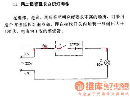
Using diode to extend the life of incandescent
In the places which are less demand of illumination such as the stairs, corridors, toilets and so on, this method can be used to extend lamp life. That's to add a rectifier of which current is 1A and voltage is higher than 400V in pulling switch.
(View)
View full Circuit Diagram | Comments | Reading(702)
Led lamps controller 2
Published:2011/4/7 2:23:00 Author:Ecco | Keyword: Led lamps controller
View full Circuit Diagram | Comments | Reading(631)
Led lamps controller 1
Published:2011/4/7 2:22:00 Author:Ecco | Keyword: Led lamps controller
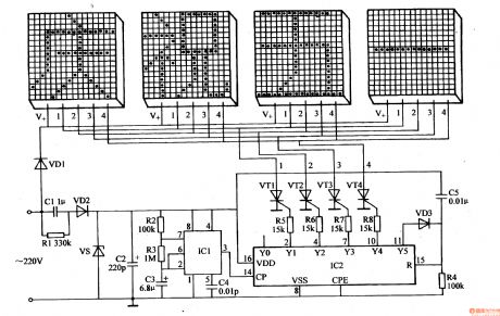
The LED festival character display lights controller can display four sentences and four words composing of many LEDs(such as celebrating May Day and long live our motherland ), and they display in time sequence to add festive atmosphere to festive night.
Working principle:
The LED festival lights controller circuit is composed of power supply circuit, pulse generator, control circuit and LED display circuit. It's shown as the chart of 1-165.
Power supply circuit consists of step-down capacitor Cl, discharge resistors Rl, rectifier diodes VDl, VD2, Zener diode VS and filter capacitor C2.
The pulse generator is composed of integrated circuit ICl, resistors R2, R3 and capacitors C3, C4.
Control circuit consists of decimal counting / pulse divider integrated circuit IC2, diodes VD3, resistors R4-R8, capacitor C5 and thyristor VTl-VW.
(View)
View full Circuit Diagram | Comments | Reading(1546)
Automatically detecting the battery voltage indicator circuit diagram
Published:2011/4/7 21:11:00 Author:Ecco | Keyword: Automatically detecting, battery voltage indicator
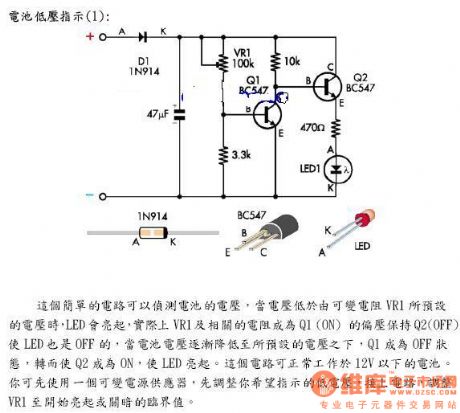
the battery voltage indicator
This simple circuit can detect the battery voltage. When the voltage is lower than the preset voltage set by the variable resistor VR1, LED will light up, in fact, related resistance and VR1 will be bias maintain Q2 (OFF) of Q1(ON), so that the LED is OFF. When the battery voltage is gradually reduced to below the preset voltage, Q1 becomes OFF, Q2 becomes ON, the LED lights up. This circuit can work under the 12V battery. You can first use a variable power supply, adjust the the low-voltage you want, connect to the circuit, adjust VR1 to critical value of beginning to light or dark.
(View)
View full Circuit Diagram | Comments | Reading(1716)
FET drive time-cycle type flash circuit
Published:2011/3/28 19:56:00 Author:may | Keyword: time-cycle type flash, FET drive time-cycle type flash
FET drive time-cycle type flash circuit is shown in the diagram:
(View)
View full Circuit Diagram | Comments | Reading(683)
Transistor TBZ363C20V8, TBZ363C5VV, TBZ363C6V4, TBZ363C7 V0 internal circuit diagram
Published:2011/3/31 22:49:00 Author:Rebekka | Keyword: Transistor , internal circuit
Transistor TBZ363C20V8, TBZ363C5VV, TBZ363C6V4, TBZ363C7 V0 internal circuit diagram is shown as below.
(View)
View full Circuit Diagram | Comments | Reading(627)
Crystal diode QZX363C15 internal circuit diagram
Published:2011/4/1 1:40:00 Author:Rebekka | Keyword: Crystal diode
Crystal diode QZX363C15 internal circuit diagram is shown as below.
(View)
View full Circuit Diagram | Comments | Reading(623)
| Pages:70/72 At 20616263646566676869707172 |
Circuit Categories
power supply circuit
Amplifier Circuit
Basic Circuit
LED and Light Circuit
Sensor Circuit
Signal Processing
Electrical Equipment Circuit
Control Circuit
Remote Control Circuit
A/D-D/A Converter Circuit
Audio Circuit
Measuring and Test Circuit
Communication Circuit
Computer-Related Circuit
555 Circuit
Automotive Circuit
Repairing Circuit