
LED and Light Circuit
Index 65
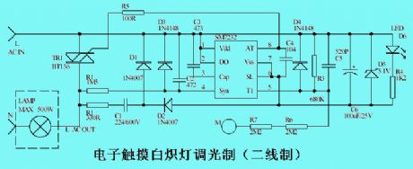
The intensity-scale of electronic touch dimmer incandescent
Published:2011/6/27 4:18:00 Author:Ecco | Keyword: intensity-scale , electronic, touch , dimmer incandescent
View full Circuit Diagram | Comments | Reading(1423)
TV control automatic light circuit
Published:2011/6/27 4:34:00 Author:Ecco | Keyword: TV , control , automatic light
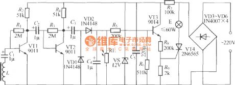
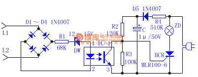
Watching TV requires certain brightness around, or a long time watching TV is not conducive to protect eyes. The circuit shown as the chart is the background small lamps lighting circuit controlled by TV. When the TV is turned on, the small lamps will be automatically lit, When the TV is turned off, the lights can automatically turned off, while watching TV during the day, the lights will be blocked and not be lit up automatically. The electromagnetic coil L need to be self-made, you should find the input or output transformer core in an old radio, and cut one side of the coil, the core will change into a U shape.
(View)
View full Circuit Diagram | Comments | Reading(749)
The human body sensor lights with LM358 designing
Published:2011/6/27 5:07:00 Author:Ecco | Keyword: human body, sensor lights , designing
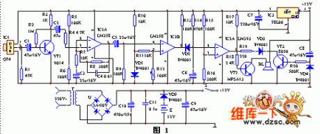
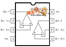
The infrared sensors, signal amplifier circuit, voltage comparator, delay circuit and sound alarm circuit form the human body sensor lights with LM358 designing. IC1 infrared detection sensor can detect the infrared radiation signals in front of the body, and the output pin ② of IC1 outputs weak electrical signals, which is amplified by the first-class amplification circuit composed of transistor VT1, then input to the op-amp IC2 and done the high-gain, low-noise amplified, then this time the pin ① of IC2 outputs enough strong signals. IC3 is used as a voltage comparator.
(View)
View full Circuit Diagram | Comments | Reading(4264)
Tel indicator circuit
Published:2011/6/27 4:16:00 Author:Ecco | Keyword: Tel , indicator circuit
View full Circuit Diagram | Comments | Reading(698)
The LED suggested circuit powered by ordinary AAA batteries
Published:2011/6/20 9:40:00 Author:Fiona | Keyword: The LED suggested, powered by ordinary AAA batteries
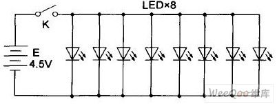
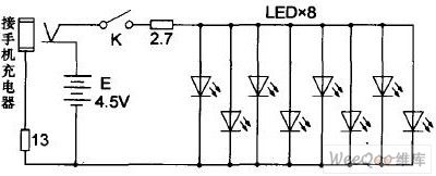
When the battery voltage is 4.38V,the measured current is about 150mA, LED's voltage drop is 3.2V. In order to effectively extend battery using time, the writer decides to cascade a small value of current limiting resistor behind the button switch K, after the repeated test,the current is 120mA when using 2.7Ω resistor,the brightness is no significant change. If it is too expensive,the circuit can use 220V AC power which requires a suitable power adapter,the writer suggests to choose the abandoned mobile home battery charger, because the mobile phone chargers plug have various different shape,it should be transformed by mono headphones plug in advance,output voltage of the charger which is found by the writer is 6.28V.
(View)
View full Circuit Diagram | Comments | Reading(1016)
LED lights supplied power by telephone lines circuit
Published:2011/6/20 22:18:00 Author:Fiona | Keyword: LED lights, supplied power by telephone lines
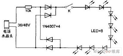
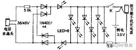
Taking into account the LED lights of telephone lines exist a negative impact on the internet, so that it can't always be connected to the telephone line,the writer also has some transformation of the light,the circuit after transformation is shown in Figure 2,changes the middle of the 6 LED in parallel,while increases a 3.6V lithium-ion cell phone batteries,usually uses the built-in of new work lithium electricity,when the limiting resistance is 5.6Ω,the operating current is about 120mA, brightness is more satisfactory.It can still use insert telephone extension interface lighting in emergency,operating current after transformation is about 4.6mA, brightness is said to the past.
(View)
View full Circuit Diagram | Comments | Reading(2050)
LED emergency light charged by own lead acid battery circuit
Published:2011/6/20 22:44:00 Author:Fiona | Keyword: LED emergency light, charged by own lead acid battery
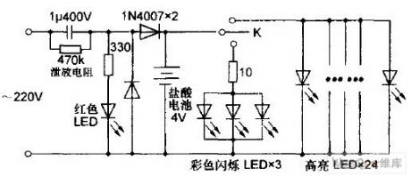
When the lead-acid battery voltage is 4V, the measured work current of the lights is about 60mA, bright LED current is more than 600 mA.So the big current makes lighting time after each full charge not be too long and damages the internal structure of the battery so that shorten the life,so it is necessary to string into a current-limiting resistance of small resistance with highlight LED.After numerous experiments, when selecting 1.2Ω,working current eventually drop to 320 mA, while the brightness change is not obvious,Because the lamp hasn't changed much, the circuit of after transformation is omitted.
(View)
View full Circuit Diagram | Comments | Reading(2560)
The instrument board lighting circuit
Published:2011/6/21 6:10:00 Author:qqtang | Keyword: instrument board, lighting circuit
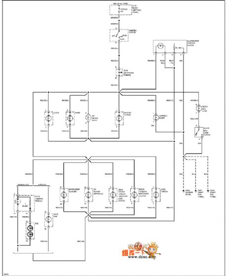
The instrument board lighting circuit is shown as above.
(View)
View full Circuit Diagram | Comments | Reading(657)
LED Transmitter Linearity-Control Circuit
Published:2011/6/11 20:18:00 Author:Robert | Keyword: LED, Transmitter, Linearity, Control
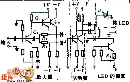
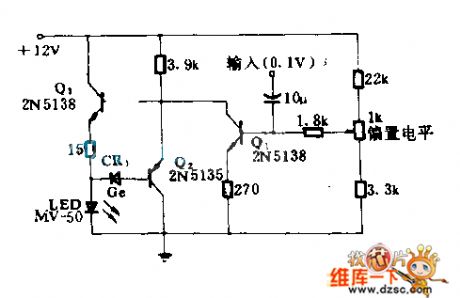
In analog system, the LED's linearity is required highly. But the linearity is different for different LED and the linearity would change as the temperature changing. This control circuit's LED driver and signal-amplifier circuit can keep the LED's linearity. The amplifier uses a couple of complementary transistors Q1 and Q2 for using to further reduce the secondary distortion. By the R1, R2 and C1's feedback it provides a 75Ω input resistance. The amplifier would send the input signal to a couple complementary driver and the driver's collector polar would output AC coupled signal on the LED. By appropriate choice of R3 it can adjust the bias current. (View)
View full Circuit Diagram | Comments | Reading(695)
The phone flasher
Published:2011/6/17 7:07:00 Author:Borg | Keyword: phone flasher
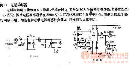
E.g 14 the phone flasherThe phone ring voltage makes the Neon bulb conducting, and the photocoupler U triggers SCR conducting and the bulb is glowing, see as Figure 20-14. The frequency of the ring voltage is often at 20Hz or so, and the bulb is flashing at the frequency. The the load is the bulb, C1 will be useless. If the ring or the relay, etc, are the load, C1 is used to remove the sparkle disturbance.
(View)
View full Circuit Diagram | Comments | Reading(696)
The flash signpost light circuit
Published:2011/6/17 8:05:00 Author:Borg | Keyword: flash signpost light
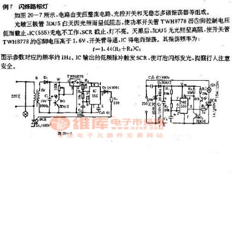
E.g 7 the flash signpost circuitSee as figure 20-7, the circuit consists of the transforming rectifier circuit, light control switch and non-steady multi-resonance oscillator, etc.The light dependent triode 3DU5 is in a low impedance due to the light in the daytime, which makes the power switch pipe TWH878 block due to the low control voltage of 5-pin, and IC(555) doesn't work without power, SCR is blocked, the light is OFF. The it's dark outside, 3DU5 is in a high impedance without light, which makes the voltage on 5-pin of TWH8778 higher than 1.6v, the switch pipe is conducting, IC is oscillating because of getting power. The oscillating frequency is f=1.44(R2+R3)C2.The frequency responding to the figured parameter is about 1Hz.
(View)
View full Circuit Diagram | Comments | Reading(616)
The flash circuit power supplied by the AC power grid
Published:2011/5/22 8:33:00 Author:Crystal Liu | Keyword: The flash circuit power supplied by the AC power grid, BC172B
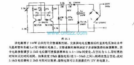
This circuit is used for alternate hige control of 100W incandescent lamp.The Dc voltage after rectifying Ac power supply voltage add to the circuit which is series connection one-way thyristor and load La(light) .Alternate hige frequency decided much harmonic oscillator's oscillation frequency.The picture circuit parameters adjustment 2.5kΩ potentiometer can make oscillation frequency range from 0.5Hz to 1Hz,occupies emptiescompared is 0.5,light time and blackout time is the same.If change 27kΩ passive resistance(range 5~50kΩ),the occupies emptiescompared will be changed,at this time 2.5kΩ potentiometer and 2.2kΩ resistance can cancel,Passive resistance can directly meet in the power which is 12V.
(View)
View full Circuit Diagram | Comments | Reading(607)
MHZ LED Pulse Modulation Circuit Diagram
Published:2011/5/11 1:45:00 Author: | Keyword: MHZ, LED, Pulse Modulation
Thecircuit is a GaAsP LED which is quickly switch-on to supply required low driven impedance.The LED can be used as high speed pulse lamp-house in fiber or other light.Q1 supplys volts d.c. and information for Q3(follower).Q2 detects output current, and limits it at about 30mA.The max switch-on time is 12ns.
(View)
View full Circuit Diagram | Comments | Reading(1069)
A Driving Circuit For Driving LED
Published:2011/5/18 21:47:00 Author:Robert | Keyword: Driving, LED

This circuit converts the single port's input signal to balanced differential driving signal and then this signal is send to 75Ω transmission line. The line's other port is connected to LED which is used as the input of optical coupling receiver. The phase reverser A changes the logic 1 to be logic 0 to make the Q1 connected and make B's output be 1. And the Q2 is disconnected and D's output becomes 0. So the logic 1 means that the Q2 borrows current from the transmission line and the LED and then the door D's output port absorbs the current. Or, Q2 would lend current to the transmission line and B absorbs the current, then D1 is connected to make the optical coupling receiver OC1's LED disconnected.
(View)
View full Circuit Diagram | Comments | Reading(696)
Small Emergency Light Circuit With Battery Protection
Published:2011/6/7 18:49:00 Author:Robert | Keyword: Emergency Light, Battery Protection
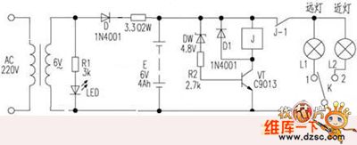
When the battery's output voltage is normal, the dw is punctured, vt is connected and also the relay is connected. The high beam or low beam light can be controlled by k to work. When the battery voltage is lower than 5.4V, the dw is disconnected to make the vt disconnected and the j open. The high beam or low beam light can not work continuously, so e stop discharging. This could protect the battery efficiently.
(View)
View full Circuit Diagram | Comments | Reading(817)
Automatical Lighting Lamp Circuit Composed Of Photoresistor
Published:2011/5/27 7:58:00 Author:Robert | Keyword: Automatical, Lighting, Lamp, Photoresistor
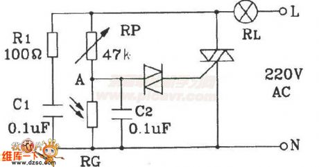
The Automatical Lighting Lamp Circuit Composed Of Photoresistor is widely used in hospital, students apartments corridor and puclic places. It would not light during the day and would light during the night.
(View)
View full Circuit Diagram | Comments | Reading(865)
Typical RGB LED Driver Chip Application Circuit with I2C Interface
Published:2011/6/3 20:37:00 Author:Michel | Keyword: RGB LED, Driver Chip, Application Circuit, I2C Interface
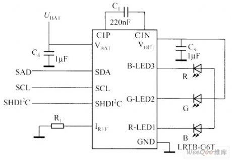
Have you ever seen the time in the dark via mobile phone?In this case,bright backlight and dark environment are in sharp contrast.which makes eyes uncomfortable.Therefore, it is necessary to adopt ICON mode,that's to say,it displays LCD panel time or the user defined picture through tiny current.If this must be realized by PWM brightness control,then the processor generates a continuous low frequency PWM signal in standby mode.In NCP5602, the function is realized by using hardware and commanding figures.The typical RGB LED driver chip application circuit with I2C interface is showed as the picture. (View)
View full Circuit Diagram | Comments | Reading(5171)
CAT3200/CAT3200-5 Driver White Light Circuit
Published:2011/5/23 21:25:00 Author:Michel | Keyword: CAT3200/CAT3200-5 Driver White Light Circuit
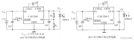
CAT3200 and cat3200-5 is boost converter of switching capacity and they output adjustable voltage with low noise.CAT3200-5 regular output voltage is 5V and it can use outter voltage to adjust output voltage.Their frequencies is 2MHz pao lotus pump and the broad input voltage(2.7-4.5V) can support the maximal output load,100mA which can help the device be used in batteries' power supply perfectly.Their shutoff control inputallows the device to enter power-fail mode and allows the mains current is under 1μA.When it shortcircuits or overloads,the device can get the upper limit turn current and overheating proctecion. (View)
View full Circuit Diagram | Comments | Reading(593)
Driving White LED Circuit
Published:2011/5/18 9:45:00 Author:Joyce | Keyword: Driving White LED
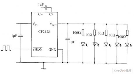
CP2128 is a step-up DC/DC converter of low noise and set frequency.If the input voltage isbetween 2.7 to 4.5 V,this device can produce 5v output voltage, and the current output can reach 100MA . Few external components make CP2128 a very suitable choice for small-sized applications in which battery is used as the power source . CP2128 charge pump can reduce fluctuation of output and input when full loaded and zero loaded. With overtemperature protection function, CP2128 can support continuous UOUT grounding. Because it has a high switching frequency, small ceramic capacitors are disposable.(1) the technical characteristics of CP2128The main technical characteristics CP2128 are as follows.①low noise and fixed frequency.②the output current: 100mA.③switching frequency: MHz 1.8.④fixed output voltage: 5 (1± 4%) V.⑤input voltage: 2.7 to 4.5 V.⑥automatic soft start to reduce inrush current.⑦no inductance.⑧when shut off.Icc<1μA(2) The typical application circuit of CP2128Application areas of CP2128 are: mobile phones, digital cameras, MP3, PDA, notebook computers, GPS receiver. The typical application circuit of CP2128 is as shown in the figure . (View)
View full Circuit Diagram | Comments | Reading(746)
The rotating speed test circuit of photo interrupters
Published:2011/5/26 22:09:00 Author:Borg | Keyword: rotating speed, photo interrupters

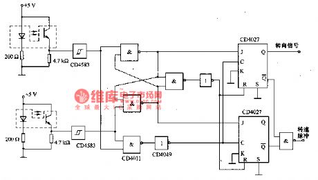
The figure is a rotating speed test circuit of photo interrupters. The circuit is equiped with 2 photo interrupters which are installed in 2 discs with a silt, it can be used to test the rotating speed and steering direction,besides, it canlink CD4027 to corresponding display equipment.
(View)
View full Circuit Diagram | Comments | Reading(1096)
| Pages:65/72 At 20616263646566676869707172 |
Circuit Categories
power supply circuit
Amplifier Circuit
Basic Circuit
LED and Light Circuit
Sensor Circuit
Signal Processing
Electrical Equipment Circuit
Control Circuit
Remote Control Circuit
A/D-D/A Converter Circuit
Audio Circuit
Measuring and Test Circuit
Communication Circuit
Computer-Related Circuit
555 Circuit
Automotive Circuit
Repairing Circuit