
LED and Light Circuit
Index 66
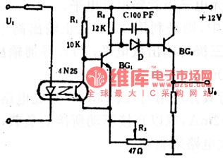
The current supervision circuit of photocoupler
Published:2011/5/26 22:25:00 Author:Borg | Keyword: supervision circuit, photocoupler
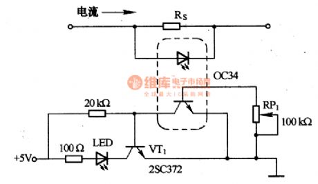
This is a current supervision circuit of photocoupler. In the tested current wires, we put in a resistance of Rs to the test, when the current reaches the regulated value, the voltage on Rs is dropping and the diode in the photocoupler is passable, so the transistor is on, then we cut it offby keeping the grounded potential of VT1 under 0.4V, so the LED is off. When the tested current is dropping, the currents in the diode and transistor of the photocouplerare dropping, so the potential of VT1 rises and it is passable, then the LED is glowing.
(View)
View full Circuit Diagram | Comments | Reading(817)
The burglar-alarm system circuit of LED
Published:2011/5/26 22:31:00 Author:Borg | Keyword: burglar-alarm system, LED
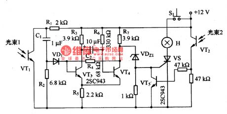
This is a burglar-alarm system circuit of LED. To enlarge the alarm range, the circuit is installed with two LED as the light receiver. The light resource is a infrared ray LED, to reduce the interruption from other rays, it needs to modulate the LED ray. If the beam of the LED is shadowed, the NPN of VTI stops work, and CI generates electricity through VD1, and the base electrode of VT3 is provided with current and VT3 is passable. In the meantime, the single stable circuit consisting of VT3 and VT4 is in a temporarily stable state.
(View)
View full Circuit Diagram | Comments | Reading(1068)
The trigger timing circuit of LED
Published:2011/5/23 2:09:00 Author:Borg | Keyword: trigger timing circuit, LED
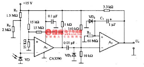
This is a trigger timing circuit of LED. In the circuit, A1 is the comparator, A2 is the single trigger timer. When the light obstructed, the current in VD, the LED, is changing, and the current is output by A1 then it triggers A2,then A2 converts the current into a low LEV and keep it for 60S(it is decided by R3 and CI). The sensitivity to the light of VD can be changed by the resistances of R1 and R2, but the ratio between the two resistance values is stable, so that VD could be provided with a certain reverse bias voltage.
(View)
View full Circuit Diagram | Comments | Reading(654)
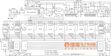
The 8-bit LED dynamic display circuit of ICM7218A
Published:2011/6/10 3:53:00 Author:qqtang | Keyword: LED dynamic display, 8-bit
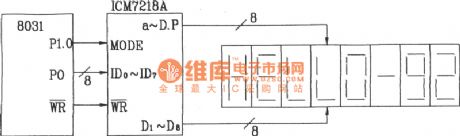

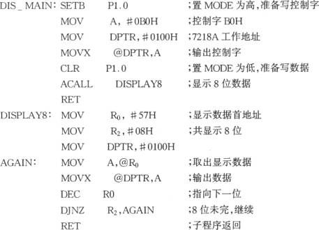
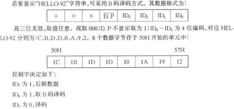
The 8-bit LED dynamic display circuit of ICM7218AIn the figure is the 8-bit LED hardware scanning dynamic displayer consisting of 8031 and ICM7218A. As ICM7218A has functions of both software decoding and hardware decoding, so there two ways to make the displayer indicate HELLO-92 , which are software decoding and hardware decoding. The following will introduce them respectively.The software decoding programmingFirstly, find out the code of the letters that need to indicate. According to the corresponding relationship between a,b ,c,d,e,f,g and data bit, we can get that in H, a and d are 0, the others are l, i.e 10111110 or BEH.
(View)
View full Circuit Diagram | Comments | Reading(1139)
The 9-bit LED LEV displaying drive circuit of LB1409
Published:2011/6/10 5:00:00 Author:qqtang | Keyword: 9-bit LED, drive circuit
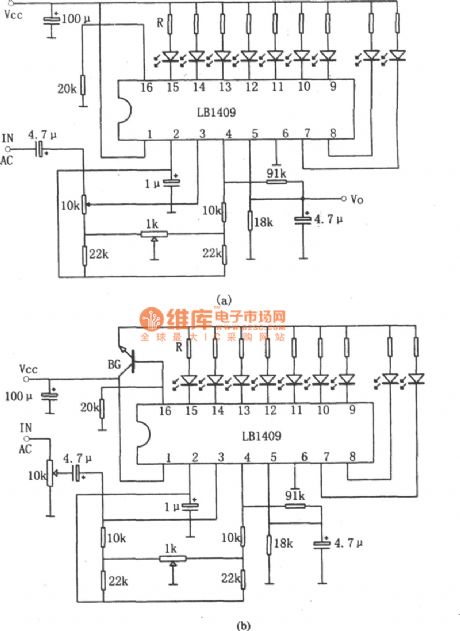
In the figure is the 9-bit LED LEV displaying drive circuit of LB1409. Figure (a) is the LEV display drive circuit which consists of LV1409, figure (b) is the LEV display drive circuit of application reference voltage. LB1409 is produced by Toyo, Japan, and the local products, such as D1409 and SL1409, are like it, and they can replace it. The LB1409 input pole is indicated with 9 stick-shape red or green LED. Inside the circuit, there is a DC amplifier, whose gains can be changed by external resistors. (View)
View full Circuit Diagram | Comments | Reading(1531)
Using Constant-Voltage Current-Limited Floating-Charge Method Power-Outage Lighting Circuit
Published:2011/5/20 0:05:00 Author:Robert | Keyword: Constant-Voltage, Current-Limiting, Floating-Charge, Power-Outage, Lighting
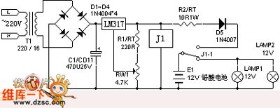
The commercial power would be changed to output 15.1V constant DC voltage through t1's step-down, d1~d4's rectifier, c1's filter and the lm317's regulator. The relay J1 is connected to make the r2, d5 process the current-limited floating charge to the battery. This would make sure the battery in full energy mode anytime. When the commerical power have a outage, j1 would be disconnected and the 12V lead-acid battery begins to supply to the lamps for emergency lighting. The 12V lead-acid battery's floating charging voltage is 14.4V. Because of the diode D5 has been connected in to prevent back discharge, it should adjust the rw1 to make the output voltage of lm317 be 15.1V. This could make sure the battery has enough voltage.
(View)
View full Circuit Diagram | Comments | Reading(1216)
The LED torch circuit
Published:2011/6/10 3:08:00 Author:qqtang | Keyword: LED torch
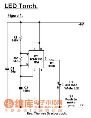
Generally, a problem of the small torch is that the life span of the battery is too short. According to the statistics, the power of a common torch is about 2W. See as the figure, the LED torch consumes power of 24mV/s, so 4 cells of No.5 can provide with more than 80 times of services(which means it can use for a month). Though the brightness of the torch is not high, but it is enough for ordinary torches. One of the cores of the torch is a 7555 time based circuit( the ordinary 555 can be used ). (View)
View full Circuit Diagram | Comments | Reading(1554)
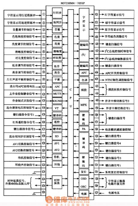
The internal circuit and pin functions of M37210M4-705SP and its signal flow circuit
Published:2011/6/5 21:24:00 Author:Seven | Keyword: internal circuit, pin functions, signal flow
(View)
View full Circuit Diagram | Comments | Reading(1198)
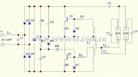
The dual-pipe energy saving lamp circuit
Published:2011/6/3 9:15:00 Author:Seven | Keyword: dual-pipe, energy saving lamp
View full Circuit Diagram | Comments | Reading(1361)
The glowing digit circuit
Published:2011/6/7 2:42:00 Author:qqtang | Keyword: glowing digit
The working principle is as follows. N1~Nn are 9-bit micro digital switch, when being set, each switch can only links to 1 bit(1~9), others are cut off. When all 1~9 are cut off, it indicates 0 . For example, if the front 3-bit digital pipes of N1~N3 indicate 098 , then N1 is off, the 9th bit of N2 is on, the 8th bit of N3 is conducting; the other set method is the same. Among the screens, N1~Nn are 1.5 inch highly bright overcast pipes, which are corresponding to N1~Nn. (View)
View full Circuit Diagram | Comments | Reading(739)
The log transmission circuit of LED signals
Published:2011/5/21 6:08:00 Author:Borg | Keyword: log transmission, LED signals
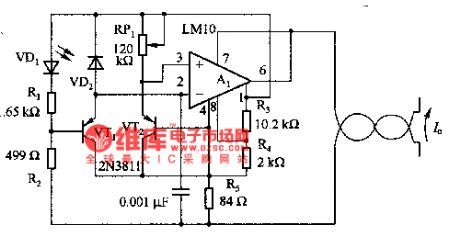
The figure is a transmission circuit of shifting D/A with LED. The circuit is to do log transmission to VD2 photo-current in the tested area, and the current is delivered to distant equipment in terms of dual-line currents. RP1 is used to set the intermediate range which is to be tested, and the temperature nature of the transformation coefficient is compensated by R5.
(View)
View full Circuit Diagram | Comments | Reading(598)
The photocoupler and its application circuit
Published:2011/5/21 4:52:00 Author:Borg | Keyword: photocoupler, application circuit
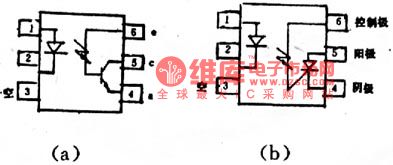
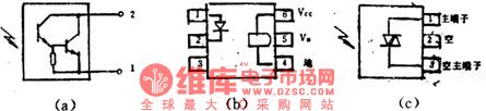
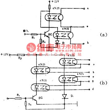
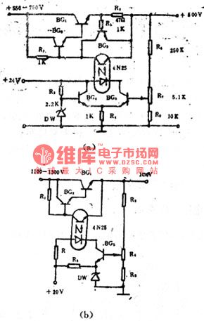
The photocoupler is a semiconductor photoelectric device which has been developed in recent years. Due to its little size, long lifespan, good anti-jamming function, wide working temperature range and total separation of input and output without touch, etc, it is widely used in electronic technology area and industrial automation control, besides, it can replace relays, transformers and wave chopper, so it could be used in separation circuits, switch circuit, D/A shift, logic circuit, overcurrent protection, long line transmission and LEV distribution, etc.
(View)
View full Circuit Diagram | Comments | Reading(927)
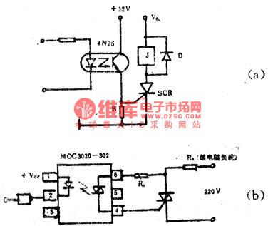
The AC control circuit consisting of photocouplers
Published:2011/5/21 5:17:00 Author:Borg | Keyword: AC control circuit, photocouplers
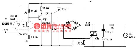
This is a AC control circuit consisting of photocouplers. The circuit is fixed with photocouplers, making the control circuit and the high voltage circuit separate the electric. The DC power supply of 5-24v/10mA controls the power of AC. When the AD voltage is over 0, VS2 gets through/cuts the line, therefore, when it is through, the current raising ratio of VS2 is low, so the high-frequency noise can be impeded. As the characters of load control are different, so the applied voltage source is not like the phase of VS2 current.
(View)
View full Circuit Diagram | Comments | Reading(966)
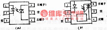
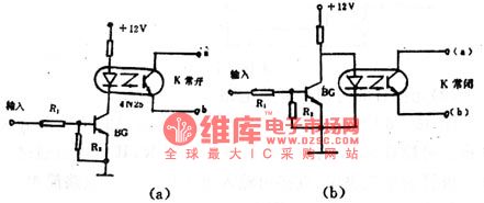
The application circuit of the photocoupler
Published:2011/5/21 4:30:00 Author:Borg | Keyword: application circuit, photocoupler
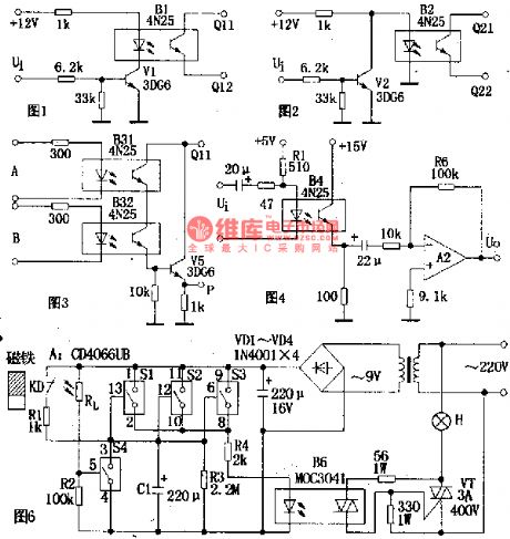
1.combination switch circuitIn the circuit of figure 1, when the input signal(ui) is a low LEV and the diode(V1) is stopped, the current of the LED in photocoupler BI is close to 0, the resistance between output terminals Q11 and Q12 is very high, which is equal to off ; the ui is a high LEV, vi is passable, the LED in BI is glowing, the resistance between Q11 and Q12 turns down, which is equal to on . As when ui is always a low LEV, the switch is off, so that it's often in high LEV state.
(View)
View full Circuit Diagram | Comments | Reading(697)
The auto gain-control circuit of photocoupler
Published:2011/5/21 20:25:00 Author:Borg | Keyword: auto gain-control, photocoupler
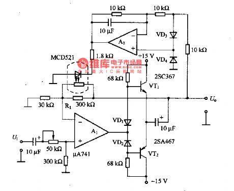
This is a auto gain control circuit of photocoupler, which is mainly consists of AC amplifiers and rectifier circuits. Suppose that we put a AC signal on the non-inverting input terminal of AI, if the input signal is lower than the set value, after it was output by A1 and rectified by A2, the current which go across the LED of MCD521 is minor, so the resistance of the light dependent resistor (LDR) in MCD521 is higher than R1. Therefore, the maximum of total resistance is 30OkΩ(the resistance of RI), and the gain of AI becomes the largest.
(View)
View full Circuit Diagram | Comments | Reading(1696)
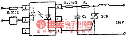
light control flash safety lights circuit
Published:2011/5/15 2:26:00 Author:John | Keyword: safety light
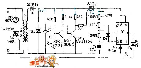
This circuit applies to safety lights in the construction site.
At the construction site, the two points A and B is put in the grid. The electricity of 220V is stepped-down by transformer B and the diode D1. Afterwards, the electricity passes through rectifier DW and filter C1 filter. Then, the DC electricity of 9V is provided to a photoelectric switch. DW affects well as a dual role of a rectifier and a regulator. During the day under strong light, photoelectric switch blocks. SCR1 has no trigger current, being in the off state. And the red signal ZD light does not shine. When in the night, photoelectric switch is in the on state. The oscillator circuit composed by IC and other components opens to work. Ultra-low frequency rectangular pulse is output by the IC constantly. SCR2 opens under this high pulse conduction and closes in the low level. As a result, the twinkling lights can be seen.
(View)
View full Circuit Diagram | Comments | Reading(636)
50kHs Frequency Light Transmitting Circuit
Published:2011/5/22 0:58:00 Author:Robert | Keyword: 50kHs, Light, Transmitting
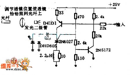
This circuit uses the pulse speed control system with central frequency of 50kHs. It takes the feedback to the transmitting audio signals to change the pulses speed. Thus it would drive the LED coupled to the optical fiber. The LED uses General Electric Company's LED55C or other similar LED. The optical transistor at the other end of the optical fiber would receive and decode the light signals to return the audio signals.
(View)
View full Circuit Diagram | Comments | Reading(631)
LED Modulator Circuit
Published:2011/5/22 2:27:00 Author:Robert | Keyword: LED, Modulator
This circuit uses the overlay typetransistors. This transistor's transmitting area is made up by several little transmitting area. And there is a layer of metal overlaying on it to make the transmitting area connected. So it could get large-power outputunder high-frequency conditions.
In this circuit it is requiredshielding. In communication system it can be used to modulate thebeam of light.
(View)
View full Circuit Diagram | Comments | Reading(759)
Integration (Quadrature) Demodulation Circuit
Published:2011/5/22 3:03:00 Author:Robert | Keyword: Integration, Quadrature, Demodulation
In this picture, the photodiode array is irradiated from the communication system's LED and then it would convert the light signals on the broadcast band. The circuit is similar with the 1:1 balanced-unbalanced converter and it has the single-channel input and double-channel output. The phase-shifting between the two output is 90°. The circuit would not require neutralization. It can give reasonably the high gain with low noise response.
(View)
View full Circuit Diagram | Comments | Reading(1247)
Timing Flash Circuit Driven By FET
Published:2011/5/12 23:44:00 Author:Robert | Keyword: Timing, Flash, FET
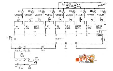
Using the circuit in the picture, it only needs a few components to make up a loop light timing control circuit. The circuit is made up by MOS time-base circuit 7555, CMOS decimal counter (pulse divider) 4017 and end-stage VMOS power transistor. The power transistor can control the lamp whose maximum current is 2A, and the resistance RV between lamp and power +VB is used for limiting current.
The time-base circuit's frequency is adjusted by the potentiometer RP (about 0.5~10Hz). The 9-stage loop register is controlled by the square wave output signal from the timing input port to change each output port to be high-voltage level in turn. Because the pin 11 is connected with the reset input pin 15, the coming of the tenth pulse would control the first lamp bright again.
(View)
View full Circuit Diagram | Comments | Reading(1087)
| Pages:66/72 At 20616263646566676869707172 |
Circuit Categories
power supply circuit
Amplifier Circuit
Basic Circuit
LED and Light Circuit
Sensor Circuit
Signal Processing
Electrical Equipment Circuit
Control Circuit
Remote Control Circuit
A/D-D/A Converter Circuit
Audio Circuit
Measuring and Test Circuit
Communication Circuit
Computer-Related Circuit
555 Circuit
Automotive Circuit
Repairing Circuit