
LED and Light Circuit
Index 64
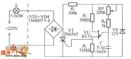
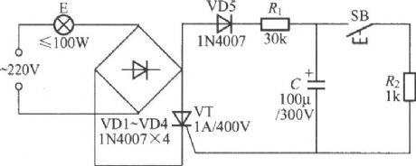
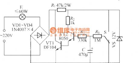
Touching adjustable timing light circuit (1)
Published:2011/7/1 2:50:00 Author:Ecco | Keyword: Touching , adjustable , timing light
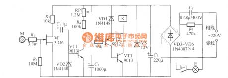
The chart shows a practical touching adjustable timing light circuit with timer time being adjustable in 1h. As long as alarm time reached, the light E is turned off, it can be used to time and turn off lights and other housing appliances.
(View)
View full Circuit Diagram | Comments | Reading(1920)
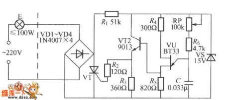
Touching dimming delay light circuit
Published:2011/7/1 2:44:00 Author:Ecco | Keyword: Touching , dimming, delay light
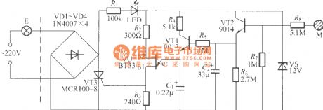
Circuit features: as long as touching the film, light will be bright and delay tens of seconds, then the light is not extinguished immediately but gradually darken until turning off. The touch switch has only two pin-out, which can directly replace ordinary light switch without having to change the original wiring. Touching the circuit once, lights can be lit 45 ~ 60s or so, if you want to change the delay time, you can adjust the resistance of resistor R6. R6 resistance is larger, the delay is longer, otherwise shorter.
(View)
View full Circuit Diagram | Comments | Reading(673)
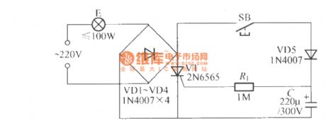
Bed safety dimmer circuit
Published:2011/7/1 3:33:00 Author:Ecco | Keyword: Bed , safety , dimmer
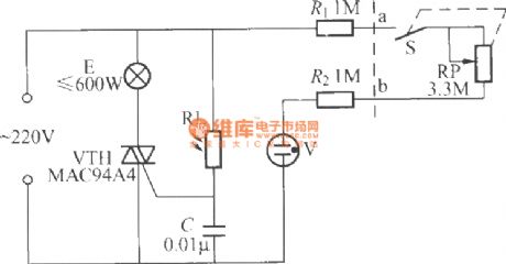
Bed safety dimmer circuit is shown as the chart, and the circuit uses the neon bulb V to couple with the photosensitive resistor RL, high-value resistors R1, R2 to isolate the dimming potentiometer RP from the electric supply phase line, and adjusting RP can change the luminance of light bulb E and turn off the light.
(View)
View full Circuit Diagram | Comments | Reading(873)
Non-touch touch delay lamp circuit
Published:2011/6/27 22:35:00 Author:Ecco | Keyword: Non-touch , touch delay lamp
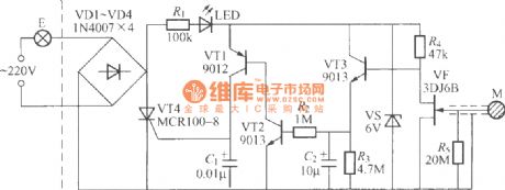
The circuit is shown as the chart, its switch panel is the full-plastic structure without any metal parts. When people use it, as long to touch the plastic panel, lights can be lit, after a delay time, the lamp is turned off. The circuit delay time depends on R2, R3 and C2's value, the data in the chart indicates the delay time being about 1 min.
(View)
View full Circuit Diagram | Comments | Reading(751)
Darlington Type Phototransistor Optical Triggered Switch Application Circuit
Published:2011/7/3 6:36:00 Author:Robert | Keyword: Darlington, Phototransistor, Optical Triggered Switch, Application
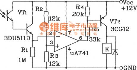
The picture shows the darlington type phototransistor optical triggered switch application circuit.
Because of using the darlington type phototransistor and operational amplifier, the very weak light can flip the circuit. If the positions of R1 and phototransistor are be reversed, or the positions of the operational amplifier's out-phase and in-phase input ports are reversed, the circuit can modified to be triggered opening by the dark. (View)
View full Circuit Diagram | Comments | Reading(1352)
Darlington Type Phototransistor Optical Control Switch Application Circuit
Published:2011/7/3 6:42:00 Author:Robert | Keyword: Darlington, Phototransistor, Optical Control, Switch, Application
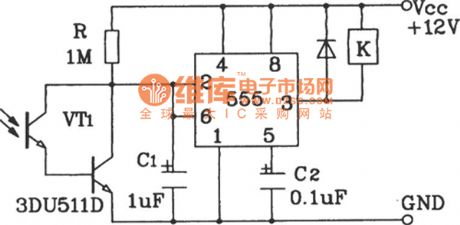
The picture shows the darlington type phototransistor optical control switch application circuit.
Because of using the darlington type phototransistor as the sensor element, it is sensitive to weak light. It is adequate for the detection of reflected light signal. (View)
View full Circuit Diagram | Comments | Reading(1636)
Silicon Controlled Capacitance Step-down LED Drive Circuit
Published:2011/7/1 8:25:00 Author:Michel | Keyword: Silicon Controlled , Capacitance Step-down, LED Drive Circuit
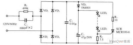
The above picture shows the silicon controlled capacitance step-down LED drive circuit.In this circuit, silicon controlled SCR and R3 constitute protection circuit, when the current flows through the LED more than the setting , SCR conducts certain Angle and the circuit's current are divided and it makes the LED work in stable condtion,which keep the LEDaway from high voltage damage.
Picture:Silicon Controlled Capacitance Step-down LED Drive Circuit (View)
View full Circuit Diagram | Comments | Reading(916)
Voltage-Sensitive Resistor Voltage Reduced Capacitance LED Driving Circuit
Published:2011/6/24 20:38:00 Author:Michel | Keyword: Voltage-Sensitive Resistor, Voltage Reduced Capacitance, LED Driving Circuit
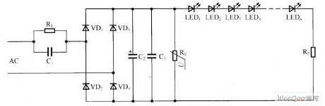
he aboved picture is a pratical voltage-sensitive resistor voltage reduced capacitance LED driving circuit 9.The difference between circuit and most application circuit is that it connects voltage sensitive resistance (It also can be transient voltage suppression LED).This resistance(transient voltage suppression LED) can effectivly run over inrush current transient voltage on undervoltage sensing to protect LED and other transistors. moment(such as lightning, the start of a great power ).Transient voltage suppressor response time is commonly ns level. (View)
View full Circuit Diagram | Comments | Reading(1332)
Electronic energy saving lamp (3)
Published:2011/6/30 2:08:00 Author:Ecco | Keyword: Electronic, energy saving, lamp
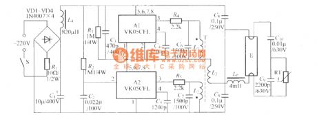
In the circuit shown as the chart, T uses E5 ferrite core with Φ0.2mm high-intensity polyester wire, and L1, L2 have about 12 to 30 turns, and L3 has 200 turns; RT uses RTC thermistor, such as MZ11B, MZ64 types.
(View)
View full Circuit Diagram | Comments | Reading(803)
The DC/AC double purpose dark room safelight
Published:2011/7/2 2:25:00 Author:Borg | Keyword: double purpose, dark room safelight

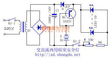
This DC/AC double purpose dark room safelight has the function of pointless auto converting switch. It is adopted with orange LED.
When the power is normally supplied, the AC 220V is rectified by the transformer, filtered by the capacitor, and then is turned into a 4V or so DC (it's 5V when it is in empty load). As the voltage of the battery in the machine is 3V, the diode D is conducting and powered by the rectifier power supply. As the BG emitter LEV is lower than the basic LEV, therefore, BG is blocked, the battery E is cut off automatically and there is no current out.When the power is off, the LEV of BG emitting pole is higher than the basic pole LEV. (View)
View full Circuit Diagram | Comments | Reading(1049)
The stepless dimmer circuit of special integrated circuits
Published:2011/6/29 0:57:00 Author:Seven | Keyword: stepless dimmer, integrated circuits
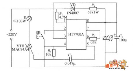
The figured circuit is the key control stepless dimmer circuit composed of HT7700A dimming special integrated circuit, which is controlled by a SB single key, and the dimming brightness has 96 stages.
(View)
View full Circuit Diagram | Comments | Reading(773)
The dual key FET dimmer circuit
Published:2011/6/29 5:10:00 Author:Seven | Keyword: dual key, FET dimmer
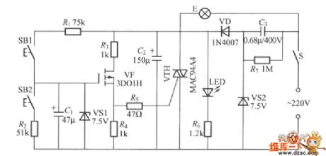
The dual key FET dimmer circuit is shown in the figure, which adopts two light touch switches to regulate the brightness, one of them is to raise the brightness, the other is to reduce to brightness. It is easy to use and its outline is pretty.
(View)
View full Circuit Diagram | Comments | Reading(1149)
The single-way thyristor dimmer circuit triggered by single knot transistor
Published:2011/6/29 21:02:00 Author:Seven | Keyword: thyristor dimmer, single knot transistor
1.To increase the stability of the bulb, we can adopt the single-knot transistor trigger circuit in the following figure.
2.See as the figured circuit, VT1 can be 3CT1 or MCR100-8 single-way transistor.
(View)
View full Circuit Diagram | Comments | Reading(2601)
The simplest dual-way thyristor dimmer circuit
Published:2011/6/29 5:35:00 Author:Seven | Keyword: dual-way thyristor, dimmer circuit
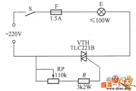
In the figure is the simplest dual-way thyristor dimmer circuit, the feature of the dual-way thyristor is that whether the AC is in its positive or passive half circle, just add a proper trigger pulse or control circuit on its control pole, the thyristor will be passable, and the conducting time is relative to the pulse width or gate current. The brightness of bulb E can be changed by adjusting RP.
(View)
View full Circuit Diagram | Comments | Reading(929)
The Dongfeng-Funshion lighting system circuit
Published:2011/6/28 20:34:00 Author:qqtang | Keyword: Dongfeng-Funshion, lighting system
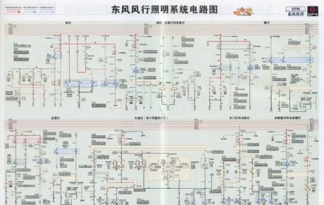
The Dongfeng-Funshion lighting system circuit is shown as above.
(View)
View full Circuit Diagram | Comments | Reading(713)
The white drive circuit composed of MAXl554
Published:2011/6/21 6:24:00 Author:Lucas | Keyword: white LED , drive circuit
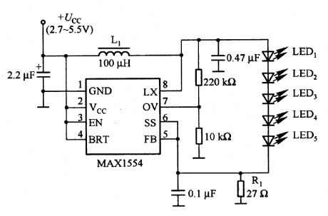
It is the white LED drive circuit which is supplied by 2 to 4 cell batteries, and the maximum luminance is constant. Rl is the current detection resistor with the resistance in 27Ω, so the LED current is about 10mA. L1 requires the use of the inductors with higher saturation and flux density for increasing the current.
(View)
View full Circuit Diagram | Comments | Reading(668)
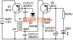
Simple LED driver
Published:2011/6/28 2:15:00 Author:zj | Keyword: Simple LED driver, 9012
View full Circuit Diagram | Comments | Reading(744)
Simple delay lamp circuit (2)
Published:2011/6/27 22:11:00 Author:Ecco | Keyword: Simple , delay lamp
View full Circuit Diagram | Comments | Reading(807)
Simple delay lamp circuit (3)
Published:2011/6/27 22:11:00 Author:Ecco | Keyword: Simple , delay , lamp
View full Circuit Diagram | Comments | Reading(662)
Simple gradually dark/light switch circuit (2)
Published:2011/6/27 22:23:00 Author:Ecco | Keyword: Simple , gradually dark, light, switch
View full Circuit Diagram | Comments | Reading(870)
| Pages:64/72 At 20616263646566676869707172 |
Circuit Categories
power supply circuit
Amplifier Circuit
Basic Circuit
LED and Light Circuit
Sensor Circuit
Signal Processing
Electrical Equipment Circuit
Control Circuit
Remote Control Circuit
A/D-D/A Converter Circuit
Audio Circuit
Measuring and Test Circuit
Communication Circuit
Computer-Related Circuit
555 Circuit
Automotive Circuit
Repairing Circuit