
LED and Light Circuit
Index 62
Light control street lamp circuit using NE555(2)
Published:2011/7/20 3:03:00 Author:zj | Keyword: Light control, street lamp circuit
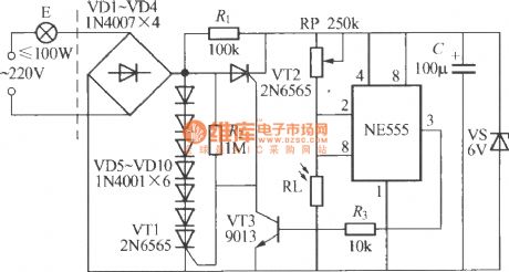
As the diagram shows the circuit is specially designed. The light control switch and the power grid adopt the two-wire connection method.It can directly replace common switch to make lighting lamp into light control street lamp. (View)
View full Circuit Diagram | Comments | Reading(1441)
3W High-power LED Drive Circuit
Published:2011/7/18 1:01:00 Author:Sue | Keyword: High-power, LED, Drive

The high-power LED easy driver is the one used in the high-power white light, but the difference is that I here use the 3W LED. The circuit will input1.2v working voltage(high capacitance NI-MH battery).The current is about 1.4-1.8A, which has a poor efficiency of about 70%. If the 150Ω resistor is replaced by a 200Ω one, and the input current is reduced to 1.0-1.3A, then a little copper sheet of an area of 3 cm² should be added on that D882 for heat radiation. I used a diagonal plier to remove the head of D882(to reduce the volume), and then welded it on the copper sheet directly. (View)
View full Circuit Diagram | Comments | Reading(4120)
HT7704 Touching stepping dimming light circuit
Published:2011/7/18 19:13:00 Author:Lucas | Keyword: Touching stepping , dimming light circuit
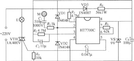
The touching stepping dimming light circuit shown aschartis composed of HT7704 integrated circuit, andHT7704 is a series of products, which has HT7704A, HT7704B and HT7704C. HT7704A is the three-step touch dimmer, and HT7704Bis the four-step touch dimmer, thenHT7704C is the two-step dimmer, that is touching on / off control, and these three application circuits arethe same.
(View)
View full Circuit Diagram | Comments | Reading(1350)
HT7700 touching stepless dimmer circuit
Published:2011/7/18 19:17:00 Author:Lucas | Keyword: touching stepless dimmer
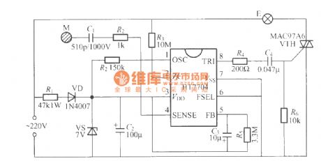
The touching stepless dimmer circuit shown as the chart is composed of HT7700 specific integrated circuit produced by Taiwan Hetai (HOLTEK). It can do stepless continuous light dimming by touching the electrodes M, in fact, the brightness of the light is changed by 96 steps.
(View)
View full Circuit Diagram | Comments | Reading(1931)
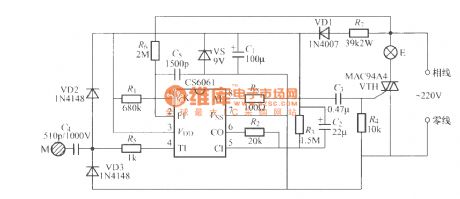
CS7232 touching stepless dimming light circuit (2)
Published:2011/7/18 19:01:00 Author:Lucas | Keyword: touching, stepless dimming light
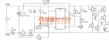
In the circuit shown as the chart, it adds a metering circuit,which can be used totransform an ordinary lamp intospecial eye protection high-dimming lamp.
(View)
View full Circuit Diagram | Comments | Reading(680)
CS6061 touching stepping dimmer circuit
Published:2011/7/18 6:12:00 Author:Lucas | Keyword: touching stepping dimmer
View full Circuit Diagram | Comments | Reading(1011)
Radio remote control lamp switch circuit
Published:2011/7/5 21:25:00 Author:zj | Keyword: Radio remote control, lamp switch circuit
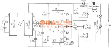
As shown in the figure itis a simple radio remote control lamp switch, press the launcher button lights ; click again, the light went out.Using themis very convenient. (View)
View full Circuit Diagram | Comments | Reading(925)
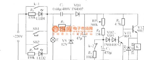
Radio remote control dimmer circuit
Published:2011/7/5 21:20:00 Author:zj | Keyword: Radio remote control, dimmer circuit

As shown in the diagram above, it is a radio remote control dimmer circuit. The radio remote control dimmer circuit adopts micro radio transmit/receive module and light modulation ASIC. So the circuit is concise and easy to produce. It works reliably. And the whole switch has only two wires for output.It can directly use it to replace the ordinary lighting switch, general lighting to remote dimmer light, without having to change the original indoor wiring. (View)
View full Circuit Diagram | Comments | Reading(2431)
Delay lamp circuit using relay (1)
Published:2011/7/7 22:01:00 Author:zj | Keyword: Delay lamp circuit, using relay
As the figue shows, it is a delay lamp using relay. It adopts the feature of relay control that the power of controlled lamp is only limited by relay contact. So you just need to use relay which has enough contact capacity. With this you can increase the power of controlled lamp. And the controlled device is not confined to the incandescent lamp. It is suitable for fluorescent lamps, electronic energy-saving lamps and other electrical devices. (View)
View full Circuit Diagram | Comments | Reading(789)
Delay lamp circuit using relay (7)
Published:2011/7/6 22:18:00 Author:zj | Keyword: Delay lamp circuit, using relay
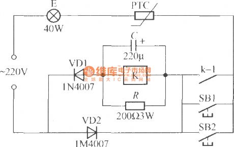
As shown in the circuit, it uses a PTC thermistor as a control element, so that the circuit is very simple. SB1 and SB2 are lights button respectively installed in two different places. Both of them can operate E. K should adopt the JRX-13F type miniature electromagnetic relay ; PTC can use color TV degaussing resistor, such as MZ72-18 type. (View)
View full Circuit Diagram | Comments | Reading(1167)
Light gun circuit diagram
Published:2011/5/13 4:23:00 Author:Ecco | Keyword: Light gun
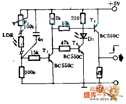
The light gunis used ascomputer handling, and it can orientate in the fluorescent screen of diaplay. When light gun receives the scanning signal from fluorescent screen, impulses light, then passes the control circuity, and the computer will show the location marked by light gun.To put a shadow shield with a window before light dependent resistor(LDR), when optical scanning electron beam makes the surface of fluorescent screen shine, the resistance value of LDR will shut down rapidly, T1, T2turn onand T3 discloses, the LED make LED turned off. That shows the light gun having indicated a word. And P1 is applied in adjusting the sensitivity of light gun.
(View)
View full Circuit Diagram | Comments | Reading(1695)
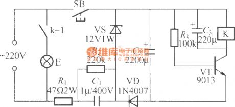
Delay lamp circuit using relay (5)
Published:2011/7/6 22:29:00 Author:zj | Keyword: Delay lamp circuit, using relay
As shown in the figure, K adopts JRX-13F, DC12V. (View)
View full Circuit Diagram | Comments | Reading(800)
LED Circuit of MAX6958/MAX6959 Driver
Published:2011/6/15 4:43:00 Author:Michel | Keyword: Driver, LED Circuit
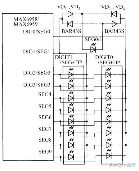
AX6958/MAX6959 is a four bit and 9 sections driver.MAX6958/MAX6959 uses six PWM(64 rank) brightness control technology, which can adjust all the average working current of LED at the same time.The single pixel level (LED) control can be achieved by expanding MAX6958 / MAX6959 function.MAX6958 / MAX6959 adoptes multiplexing technique of less pins, the 36th section drvier only uses 10 drive pins.The MAX6958 / MAX6959 standard driver connecting way is showed as the table.The MAX6958 / MAX6959 pins and LED connecting ways are different from standard connecting methods.According to the different time slot of multiplex cycle,MAX6958/MAX6959 4~7 pins act as cathode and anodic dirvers.
MAX6958/MAX6959 uses four multiplexing driving plans to drive four groups of LED cathodes in turns and every group has 9 LEDs. (View)
View full Circuit Diagram | Comments | Reading(1964)
LED producing rapid pulse light circuit
Published:2011/7/1 5:50:00 Author:Fiona | Keyword: LED, producing rapid pulse light
Only using two integrated circuits can help reduce size and power consumption (Figure 1).Normal high level pulse output by output gate G4 in the IC2 has about 2.5ns rise and fall time,and less than 10 ns pulse width, which is equivalent to three gate delays.These pulses are very suitable for pulling low the cathode potential of HLMP-CB-15-speed blue LED,and the LED anode is clamped to 5V G4 compels almost the entire 5V supply voltage to be added to the LED,so large voltage swing can ensure the LED which is welded in the edge of a small printed circuit board has the best brightness. (View)
View full Circuit Diagram | Comments | Reading(648)
MX1576 Charge-pump Drving White LED Circuit
Published:2011/6/23 23:05:00 Author:Michel | Keyword: Charge-pump, Drving, White LED Circuit
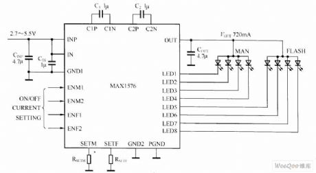
MAX1516 charge-pump can drive up to 8 white LED and it has constant current adjustment function, in order to achieve unified light intensity. The MAX1516 charge-pump can drive every group LED with 30mA which is used in blacklight.Flash group LED (LED5 ~ LED8) is the solely controlled, and they are able to use 100 mA current drive each LED ( 400 mA in total) .Through the use of adaptive 1 x, 1.5 x, 2 x mode charge-pump and current regulator of ultra low voltage difference, MAX1576 can achieve high efficiency in a lithiumion battery voltage range.Because fixed switching frequency is 1 MHz, low EMI and low input ripple. can be ensured by only using very little external components and regulation scheme optimization. (View)
View full Circuit Diagram | Comments | Reading(626)
SR03× Driving White LED Circuit
Published:2011/6/23 11:19:00 Author:Michel | Keyword: Driving, White LED Circuit
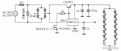
SR03 x series are dual output DC/DC power management chips without any magnetic components and the typical application circuit is shown as the aboved picture.SR036 and SR037 are two kinds of SR03 x series products of Supertex company.SR03 x series products do not need any transformer and inductor, also do not need input capacitance via high voltage,meanwhile,its work principle is very simple.SR03 x input HVin acceses rectifying 120 V or 230 V voltage of the high voltage port and it controls an external N channel mosfets or IGBT tube.The external transistor starts to conduct and charge the capacitance as the Vsource boosts when the input voltage is lower than 45V.Once when the HVin voltages is above 45 V, the external transistor will shuts off, stops charging, capacitance begins to discharge to load and maintains stable load current. (View)
View full Circuit Diagram | Comments | Reading(1120)
R1211 Driving White LED Circuit
Published:2011/6/23 11:01:00 Author:Michel | Keyword: Driving, White, LED Circuit
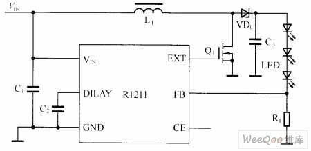
Ricoh company manufacturing R1211 series products uses the CMOS technology, is a the low power switch type boost converter of current control function.Peripheral circuit is simple and it just need a inductance, a diode, a field effect tube, and several resistance and capacitance.Its input voltage range is 2.5~5.5V which is applied to single quarter lithium ion battery or ordinary dry battery power supply occasion.The chip inside uses PWM way and it produces as much as 15 V output voltage which can drive three series LED.
R1211 series chip adopts phase compensation circuit application feedback loop which makes the boost conversion process response faster and the output voltage become more stable.The biggest R1211 duly ratio is 90%.Chip insdie builds soft start function and delay time is about 10 ms. (View)
View full Circuit Diagram | Comments | Reading(652)
MAX6964 Driving White LED Circuit
Published:2011/6/23 10:36:00 Author:Michel | Keyword: Driving, White LED Circuit
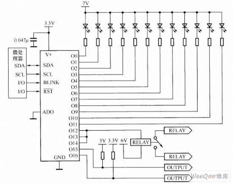
MAX6964 is a kind of I2C compatible serial interface peripheral circuit and it provide micro controller 17 output ports. The output absorbs the drain current open structure and is allowed to work in 50 mA / 7 V conditions which can drive LED or provide logic output through external voltage boost.MAX6964 inside has integrated a eight PWM current control circuit and four were global control which is used in all LED and outputs are used in current broad tuning.There are 14 brightness levels from it completely shuts off to it fully opens.In addition, every output also has independent four control bits, but the global current set is divided into 16 levels.As another choice, current control can also be configured to single eight control way, all the output can be set at a time. (View)
View full Circuit Diagram | Comments | Reading(855)
Basic White LED Drive Circuit of Switch Converter
Published:2011/6/28 5:32:00 Author:Michel | Keyword: Switch Converter, White LED, Drive Circuit
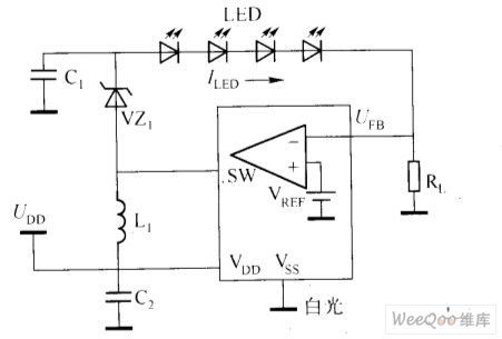
Basic White LED Drive Circuit of Switch Converter (View)
View full Circuit Diagram | Comments | Reading(680)
MA1576Y Charge - pump Driven Two Groups of LED Circuit
Published:2011/6/19 6:37:00 Author:Michel | Keyword: Charge - pump, Driven , Two Groups, LED Circuit
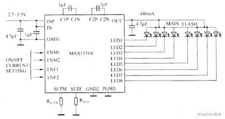
The MA1576Y charge - pump driven drive white LED Circuit is showed as above.This circuit can use 480mA general current to drivr two groups of white LED(every group has 4 white LED).For the flashing white LED group, this circuit allows each white LED current to reach 100 mA.Each group of white LED has independent the current set, pulse brightness modulation and two lines brightness control.Using the adaptive switch, in the whole process of discharging of a single lithium ion battery, circuit average efficiency can reach 83% .For the digital camera which uses white LED,it's an ideal choice to choose white LED drive circuit composed of MAX1576Y.
MA1576Y Charge - pump Driven Two Groups of LED Circuit
Picture: (View)
View full Circuit Diagram | Comments | Reading(638)
| Pages:62/72 At 20616263646566676869707172 |
Circuit Categories
power supply circuit
Amplifier Circuit
Basic Circuit
LED and Light Circuit
Sensor Circuit
Signal Processing
Electrical Equipment Circuit
Control Circuit
Remote Control Circuit
A/D-D/A Converter Circuit
Audio Circuit
Measuring and Test Circuit
Communication Circuit
Computer-Related Circuit
555 Circuit
Automotive Circuit
Repairing Circuit