
LED and Light Circuit
Index 68
Infrared Delay Lighting Switch Circuit
Published:2011/5/2 4:08:00 Author:Robert | Keyword: Infrared Delay, Lighting Switch
Infrared Delay Lighting Switch Circuit is shown below:
(View)
View full Circuit Diagram | Comments | Reading(673)
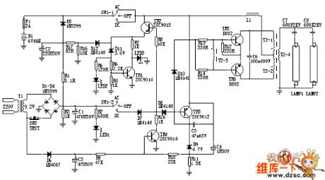
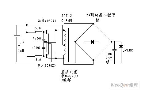
AC/DC Dual-Use Fluorescent Lighting Circuit
Published:2011/5/2 3:17:00 Author:Robert | Keyword: AC/DC Dual-Use, Fluorescent Lighting
View full Circuit Diagram | Comments | Reading(1281)
Single-transistor time relay circuit diagram
Published:2011/4/29 5:08:00 Author:Rebekka | Keyword: Single-transistor , time relay
Single-transistor time relay circuit diagram. (View)
View full Circuit Diagram | Comments | Reading(666)
High-gain operational amplifier transistor output circuit diagram
Published:2011/4/29 5:04:00 Author:Rebekka | Keyword: high-gain operational, amplifier transistor
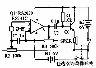
High-gain operational amplifier transistor output circuit diagram is shown as above. Connect the phone Jane to the output of 741. Transistor RS2020 single-tube-driven speaker, R2 is the volume control, R3 can adjust gain and frequency response. (View)
View full Circuit Diagram | Comments | Reading(1096)
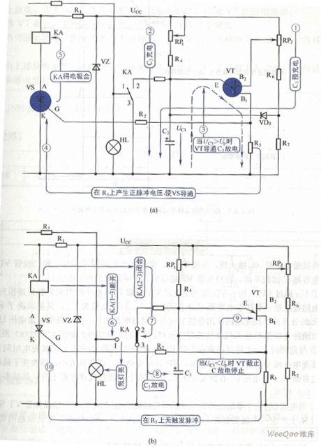
Transistor time relay circuit diagram
Published:2011/4/29 5:10:00 Author:Rebekka | Keyword: Transistor time relay
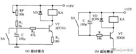
Transistor time relay circuit diagram. (View)
View full Circuit Diagram | Comments | Reading(1406)
LED boost driver circuit diagram
Published:2011/4/29 3:13:00 Author:Rebekka | Keyword: LED boost driver
LED boost driver circuit diagram. (View)
View full Circuit Diagram | Comments | Reading(1289)
Using TA7641 as LED flash launcher circuit diagram
Published:2011/4/27 3:39:00 Author:Rebekka | Keyword: LED flash launcher
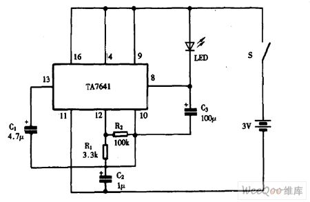
Using TA7641 as LED flash launcher circuit diagram is shown as above. (View)
View full Circuit Diagram | Comments | Reading(1369)
Flashlight circuit supplyed by battery
Published:2011/4/25 4:32:00 Author:Nicole | Keyword: flashlight, battery
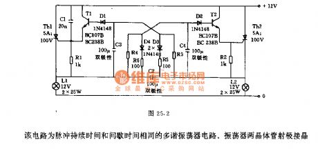
This is a multivibrator circuit with same pulse duration time and interval time. The two transistors emitter of oscillatorare connected to the gate of SCR, the two lights is flashing alternatively controlled by SCR. Capacitance C2, C3, C4 should use bipolar electrolytic capacitor. The voltage on capacitance C2 is 12V, the polarity alternatively changes with flashing rhythm. The voltage on C3, C4 changes between -12V ~Uz, Uz is SCR trigger voltage, the total of transistor T2 or T3's base-emitter cut-off voltage and diode D2 or D1's forward voltage drop is about 3V. Changing the resistance R3, R4 can change the flashing frequency, in figure, the oscillation frequency is 80/min. (View)
View full Circuit Diagram | Comments | Reading(789)
500 w Light modulation circuit diagram
Published:2011/4/20 10:00:00 Author:Rebekka | Keyword: Light modulation
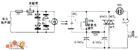
When the circuit is connected to the hi-fi equipment or at both ends of the electronic instruments speaker, the audio level can be modulated to 500W lamp by proportion. Using 3 appropriate sets of audio filters and 3 different color light Union microscopy to access to color music stage lighting effects. (View)
View full Circuit Diagram | Comments | Reading(1660)
Rechargeable flashlight circuit 1 (5)
Published:2011/4/25 1:57:00 Author:May | Keyword: Rechargeable, flashlight
View full Circuit Diagram | Comments | Reading(3225)
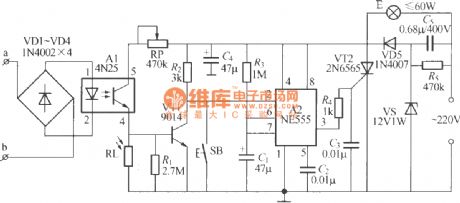
Telephone control automatic lighting circuit 1
Published:2011/4/25 4:30:00 Author:May | Keyword: Telephone control, automatic lighting
The diagram shows telephone control automatic lighting circuit. At night, when telephone rings or master takes up telephone transmitter dialing, the light can lighten; when telephone ringer stopped (no one listen) or on-hook, it can delay 10~40s, then the light can die out itself. Moreover, this circuit also set a light triggering button. The light can lighten about 40s only by pressing the button. (View)
View full Circuit Diagram | Comments | Reading(1543)
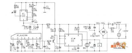
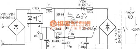
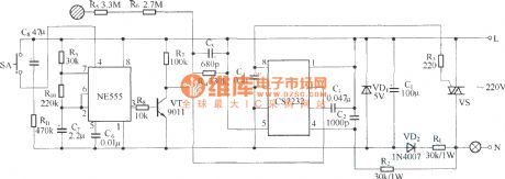
Telephone control automatic lighting circuit 2
Published:2011/4/25 4:37:00 Author:May | Keyword: Telephone control, automatic lighting
The diagram shows telephone automatic light composed of NE555 time base circuit and optical coupler. At night, when you need to make a telephone call, the light can lighten itself, it can delay 10~40s after on-hook, then the light can die out itself. Moreover, this circuit also set a triggering button. Ordinarily, when you need to lighten, the light can self lighten about 1min only by pressing the button. (View)
View full Circuit Diagram | Comments | Reading(747)
LTC3202 Drive White Light LED Circuit
Published:2011/4/22 7:55:00 Author:Joyce | Keyword: LTC3202, Drive, White Light, LED
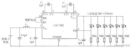
LTC3202 is a charge pump produced by Linear Technology Company,which does not need gating oscillator. The graph is the circuit of a drive white light LED powered by lithiumion batteries using LTC3202 charge pump. In order to overcome noise problems,LTC3202 uses linear control technology to make sure that the charge and discharge capacity of the conversion capacitance just meet the load current needs, and in each clock cycle,it remains a constant, thus ensuring they would not produce audio components.
The graph is the circuit of a drive white light LED powered by lithiumion batteries using LTC3202 charge pump. (View)
View full Circuit Diagram | Comments | Reading(652)
DS4301 Application Circuit
Published:2011/4/21 0:15:00 Author:Robert | Keyword: DS4301, Application
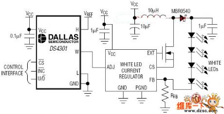
The DS4301 is a single 32-position linear digital potentiometer with 200kΩ end-to-end resistance. The wiper setting is stored in EEPROM, so the DS4301 powers up with the last stored setting. The position of the wiper is controlled through a simple three-terminal increment/decrement interface. The DS4301 is ideal for white LED backlight brightness control. Its 8-pin μSOP package, 2.4V to 5.5V supply range, and 200kΩ end-to-end resistance are especially suited for portable, battery-powered applications such as cellular telephones and PDAs. (View)
View full Circuit Diagram | Comments | Reading(617)
Half four-bit LED counting circuit
Published:2011/4/21 21:42:00 Author:Nicole | Keyword: LED counting
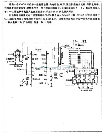
It is a CMOS half four-bit decimal counter, it has counting, latching, bit by bit scanning output circuit, protection circuit. The scanning speed can be changeable, it only needs to change a external capacitor. The power supply is 3~10V, the static power consumption is lower than 1mA, the counting frequency range is from DC to few MHz, it adopts DIP-16 foot in-line package.
The count pulse is coupled to input DG6010 count by high speed photodiode isolator SL950. 6010 sends out BCD code then transformed 7 phase drive singal by CC4511B, the singal is added to 4 bit LED to display. This counting circuit is used as faceplate counting for all kinds of instruments, such as range counting, product counting, flux counting, timing and so on. (View)
View full Circuit Diagram | Comments | Reading(687)
Composed of CS7237 self-extinguishing touch dimmer circuit circuit diagram
Published:2011/4/21 2:02:00 Author:Rebekka | Keyword: touch dimmer self-extinguishing
View full Circuit Diagram | Comments | Reading(900)
LG8150 touch stepping dimming light circuit
Published:2011/4/19 6:49:00 Author:Nicole | Keyword: dimming light
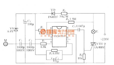
The figure is as shown, it adopts touch stepping dimming light of LG8150 integrated circuit, the finger touches M at a time, the brightness of bulb E is low brightness, middle brightness, most brightness, turn-off, low brightness... cyclic change, this circuit is suit for producing dimming table lamp. (View)
View full Circuit Diagram | Comments | Reading(866)
Lossless LED drive circuit with 24V power supply
Published:2011/4/19 6:44:00 Author:Nicole | Keyword: LED drive, 24V power supply
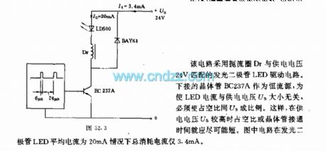
This circuit adopts LED drive circuit,its choke Dr is matched with 24V power voltage. Using under transistor BC237A as constant current source, in order to let LED current has no relationship with power voltage Us, so the duty tatio should be proportionate to Us. Thus, when the power voltage Us is higher, the duty ratio or the turn on time of transistor will short. In this circuit, in the condition of LED average current is 20mA, the total consumption current is only 3.4mA. (View)
View full Circuit Diagram | Comments | Reading(1210)
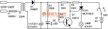
Delay light circuit with power switch integrated circuit
Published:2011/4/18 10:09:00 Author:Nicole | Keyword: Delay light, power switch
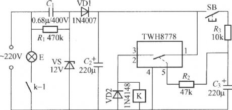
The circuit delay time is decided by the discharge time constant of R2, C3. Increasing or decreasing the capacity of C3 can adjust the delay time. When adopting the polt data, press SB once, the light E will lighting about 15s. (View)
View full Circuit Diagram | Comments | Reading(740)
Delay light circuit with power switch integrated circuit(2)
Published:2011/4/18 10:08:00 Author:Nicole | Keyword: Delay light, power switch
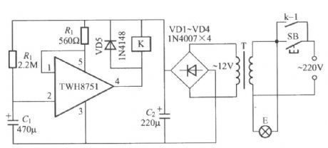
The delay time is decided by the charge time constant of R1, C1. (View)
View full Circuit Diagram | Comments | Reading(697)
| Pages:68/72 At 20616263646566676869707172 |
Circuit Categories
power supply circuit
Amplifier Circuit
Basic Circuit
LED and Light Circuit
Sensor Circuit
Signal Processing
Electrical Equipment Circuit
Control Circuit
Remote Control Circuit
A/D-D/A Converter Circuit
Audio Circuit
Measuring and Test Circuit
Communication Circuit
Computer-Related Circuit
555 Circuit
Automotive Circuit
Repairing Circuit