
Measuring and Test Circuit
Index 18
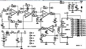
Audio Level Meter (vumeter) Circuit
Published:2012/10/25 2:30:00 Author:muriel | Keyword: Audio Level, Meter , vumeter Circuit
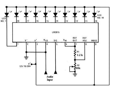
This circuit uses just one IC and a very few number of external components. It displays the audio level in terms of 10 LEDs. The input voltage can vary from 12V to 20V, but suggested voltage is 12V. The LM3915 is a monolithic integrated circuit that senses analog voltage levels and drives ten LEDs providing a logarithmic 3 dB/step analog display. LED current drive is regulated and programmable, eliminating the need for current limiting resistors. The IC contains an adjustable voltage reference and an accurate ten-step voltage divider. The high-impedance input buffer accepts signals down to ground and up to within 1.5V of the positive supply. Further, it needs no protection against inputs of ?35V. The input buffer drives 10 individual comparators referenced to the precision divider. Accuracy is typically better than 1 dB. (View)
View full Circuit Diagram | Comments | Reading(2230)
Digital metal detector circuit diagram
Published:2012/10/18 22:42:00 Author:Ecco | Keyword: Digital metal detector
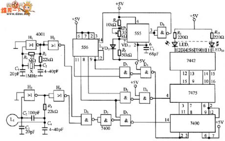
In the circuit, it uses 1MHz crystal X to generate a reference oscillation frequency, metal detector use L coil oscillator with the same nominal frequency, and NAND gate D6 will mix square wave reference signal produced by crystal oscillator and detection signal to produce a beat frequency signal circuit. 555 generates a approximately 500Hz frequency signal to drive the display 556 and NAND gate will merge the detection and display signals to add to 7490 and 7475 input ends, thereby driving the LED1 ~ LED10 emitting diodes.
(View)
View full Circuit Diagram | Comments | Reading(7907)
High-end current monitoring circuit diagram using HFP2
Published:2012/10/18 22:49:00 Author:Ecco | Keyword: High-end , current monitoring
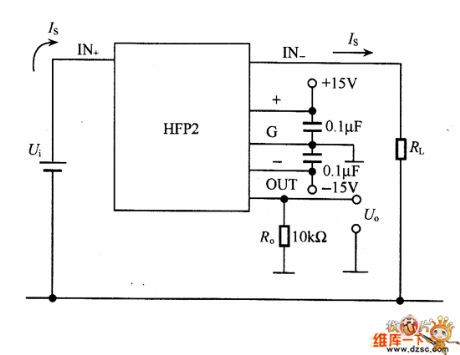
This is a high-end current monitoring circuit using DC transformer, and the working target is the same with Figure 8-9. HFP2 is a low offset voltage DC current transformer which can be easily mounted on the printed circuit board. The maximum voltage of the detected current is decided by the power between the input and output voltage of DC transformer, when the pressure reaches lkV above, the resistor Ro can not be used in principle, but the resistor is recommended by the manufacturer.
(View)
View full Circuit Diagram | Comments | Reading(1357)
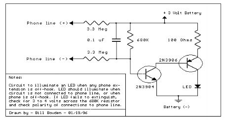
Telephone In-Use Indicator
Published:2012/10/19 0:52:00 Author:muriel | Keyword: Telephone In-Use, Indicator
View full Circuit Diagram | Comments | Reading(1103)
Decibel Meter
Published:2012/10/19 0:42:00 Author:muriel | Keyword: Decibel Meter
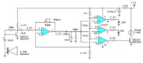
The circuit below responds to sound pressure levels from about 60 to 70 dB. The sound is picked up by an 8 ohm speaker, amplified by a transistor stage and one LM324 op-amp section. You can also use a dynamic microphone but I found the speaker was more sensitive. The remaining 3 sections of the LM324 quad op-amp are used as voltage comparators and drive 3 indicator LEDs or incandescents which are spaced about 3dB apart. An additional transistor is needed for incandescent lights as shown with the lower lamp. I used 12 volt, 50mA lamps. Each light represents about a 3dB change in sound level so that when all 3 lights are on, the sound level is about 4 times greater than the level needed to light one lamp. The sensitivity can be adjusted with the 500K pot so that one lamp comes on with a reference sound level. The other two lamps will then indicate about a 2X and 4X increase in volume.
In operation, with no input, the DC voltage at pins 1,2 and 3 of the op-amp will be about 4 volts, and the voltage on the (+) inputs to the 3 comparators (pins 5,10,12) will be about a half volt less due to the 1N914 diode drop. The voltage on the (-) comparator inputs will be around 5.1 and 6.5 which is set by the 560 and 750 ohm resistors.
When an audio signal is present, the 10uF capacitor connected to the diode will charge toward the peak audio level at the op-amp output at pin 1. As the volume increases, the DC voltage on the capacitor and also (+) comparator inputs will increase and the lamp will turn on when the (+) input goes above the (-) input. As the volume decreases, the capacitor discharges through the parallel 100K resistor and the lamps go out. You can change the response time with a larger or smaller capacitor.
This circuit requires a well filtered power source, it will respond to very small changes in supply voltage, so you probably will need a large filter capacitor connected directly to the 330 ohm resistor. I managed to get it to work with an unregulated wall transformer power source, but I had to use 4700uF. It worked well on a regulated supply with only 1000uF. (View)
View full Circuit Diagram | Comments | Reading(0)
Analog Milliamp Meter Used as Voltmeter
Published:2012/10/19 0:39:00 Author:muriel | Keyword: Analog , Milliamp Meter, Voltmeter
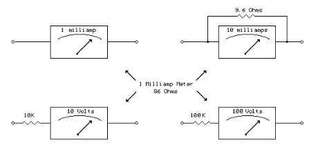
A milliamp meter can be used as a volt meter by adding a series resistance. The resistance needed is the full scale voltage reading divided by the full scale current of the meter movement. So, if you have a 1 milliamp meter and you want to read 0-10 volts you will need a total resistance of 10/.001 = 10K ohms. The meter movement itself will have a small resistance which will be part of the total 10K resistance, but it is usually low enough to ignore. The meter in the example below has a resistance of 86 ohms so the true resistor value needed would be 10K-86 or 9914 ohms. But using a 10K standard value will be within 1% so we can ignore the 86 ohms. For a full scale reading of 1 volt, the meter resistnace would be more significant since it would be about 8% of the total 1K needed, so you would probably want to use a 914 ohm resistor, or 910 standard value. The milliamp meter can also be used to measure higher currents by adding a parallel resistance. The meter resistance now becomes very significant since to increase the range by a factor of ten, we need to bypass 9/10 of the total current with the parallel resistor. So, to convert the 1 milliamp meter to a 10 milliamp meter, we will need a parallel resistor of 86/9 = 9.56 ohms. (View)
View full Circuit Diagram | Comments | Reading(1564)
Unusual Radar Detector - This unique anchient design uses a chopper amplifier
Published:2012/10/18 3:26:00 Author:muriel | Keyword: Unusual, Radar Detector
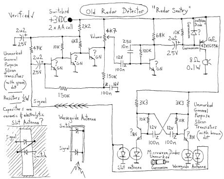
The microwave diodes are chopper-gated by a multivibrator so the RF signal level can be detected by an audio frequency amplifier. (View)
View full Circuit Diagram | Comments | Reading(3709)
How to build Economy radar detector
Published:2012/10/18 3:22:00 Author:muriel | Keyword: Economy, radar, detector
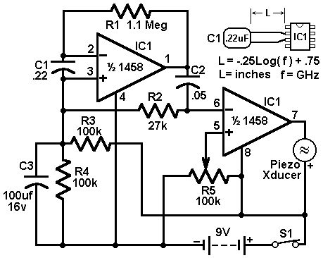
This circuit uses a 1458 dual op-amp to form a radar detector. C1 is the detector of the radar signal. The first op-amp forms a current-to-voltage converter and the second op-amp buffers the output to drive the piezo transducer. R5 sets the switching threshold of the second op-amp; normally it is adjusted so that the circuit barely triggers on background noise, then it's backed off a bit. The response of the circuit may be tuned by adjusting the length of the leads on C1. For typical road-radar systems, the input capacitor's leads should be about 0.5 to 0.6 inches long. (View)
View full Circuit Diagram | Comments | Reading(2750)
Digital Radar| Speedometer
Published:2012/10/18 3:20:00 Author:muriel | Keyword: Digital Radar, Speedometer
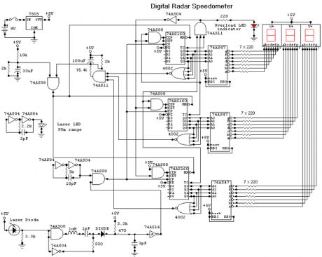
This circuit is a Digital Radar Speedometer. It allows us to evaluate the speed of any object moving, especially cars and other vehicles. The speed is calculated in kilometers per hour (KPH). Its display has three digits. This radar works with the laser reflexion. It sends laser radiation to the object and this object reflects the laser radiation to the radar. To evaluate the speed of a vehicle, we must be in front of it. In other words, the vehicle must come in our direction. The front of the radar must point the front of the vehicle. The radar has the shape of a pistol. In this radar, it has a laser LED and a laser diode. Both have a lens.
The laser LED can send a spot of light to a distance of 90 m (295 ft). It's very important that the distance range of the laser LED is 90 m, if not, the speed will not be calculated properly. The laser diode, which receives the light signal by the laser LED, must be able to detect the light which is same color as that emitted by the laser LED. The laser diode and the laser LED must be placed one beside the other. They are protected by a tinted pane. They must be placed at the front of the radar and point the outside. The radar is powered by a 9V battery and it has a SPST switch to control its power state.
The display, or the speed indicator, is placed at the rear of the radar, just on the right of the overload LED indicator. All the logic components of the circuit must be of the 74AS series and TTL type. Because they have short time of response (less than 1.7 ns) and have high frequency supports (more than 200 MHz). The radar can evaluate the speed of an object moving between 0 to 999 km/h. After this speed, the overload LED indicator will turn on and the 999 will still displayed. The radar displays the speed during 3 seconds, after this time, it displays zero (0). (View)
View full Circuit Diagram | Comments | Reading(1630)
AC Line Current Detector
Published:2012/10/18 2:06:00 Author:muriel | Keyword: AC, Line Current, Detector
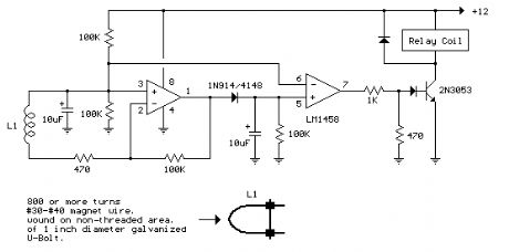
This circuit will detect AC line currents of about 250 mA or more without making any electrical connections to the line. Current is detected by passing one of the AC lines through an inductive pickup (L1) made with a 1 inch diameter U-bolt wound with 800 turns of #30 - #35 magnet wire. The pickup could be made from other iron type rings or transformer cores that allows enough space to pass one of the AC lines through the center. Only one of the current carrying lines, either the line or the neutral should be put through the center of the pickup to avoid the fields cancelling. I tested the circuit using a 2 wire extension cord which I had separated the twin wires a small distance with an exacto knife to allow the U-bolt to encircle only one wire.
The magnetic pickup (U-bolt) produces about 4 millivolts peak for a AC line current of 250 mA, or AC load of around 30 watts. The signal from the pickup is raised about 200 times at the output of the op-amp pin 1 which is then peak detected by the capacitor and diode connected to pin 1. The second op-amp is used as a comparator which detects a voltage rise greater than the diode drop. The minimum signal needed to cause the comparator stage output to switch positive is around 800 mV peak which corresponds to about a 30 watt load on the AC line. The output 1458 op-amp will only swing within a couple volts of ground so a voltage divider (1K/470) is used to reduce the no-signal voltage to about 0.7 volts. An additional diode is added in series with the transistor base to ensure it turns off when the op-amp voltage is 2 volts. You may get a little bit of relay chatter if the AC load is close to the switching point so a larger load of 50 watts or more is recommended. The sensitivity could be increased by adding more turns to the pickup. (View)
View full Circuit Diagram | Comments | Reading(1942)
The voltage output angle detection circuit using angel sensor signal conditioner UZZ9000 and magnetoresistive sensor KMZ41
Published:2012/10/12 21:46:00 Author:Ecco | Keyword: voltage output , angle detection , angel sensor , signal conditioner , magnetoresistive sensor
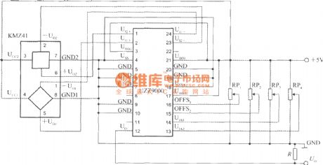
It uses the +5 V power supply, RP1 ~ RP2areoffset voltage adjustment potentiometers, RP3 ~ RP4 aregain adjustment potentiometers. R is the pull-down resistor of output end. The output voltage can be sent to a digital voltmeter to show the measured angle value.
(View)
View full Circuit Diagram | Comments | Reading(2286)
Temperature measurement circuit with 5-channel low-power programmable sensor signal processor AD7714 and thermocouple
Published:2012/10/12 21:37:00 Author:Ecco | Keyword: Temperature measurement , 5-channel , low-power , programmable sensor, signal processor , thermocouple
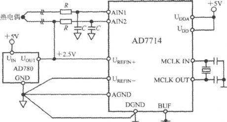
In this application, AD7714 operates in buffered mode, allowing the front terminal to connetc with decoupling capacitor in order to filter the noise on the thermocouple lead. In buffer mode, the AD7714 common mode range is narrow, the differential voltage of thermocouple is in suitable common-mode voltage range, and AD7714's AIN2 input terminal should be biased to +2.5 V reference voltage.
(View)
View full Circuit Diagram | Comments | Reading(1554)
The pressure measurement system circuit using 5 - channel low-power programmable sensor signal processor AD7714
Published:2012/10/11 21:38:00 Author:Ecco | Keyword: pressure measurement system , 5 - channel, low-power , programmable sensor, signal processor
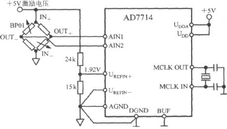
BP01 is a pressure sensor produced by Sensym Company. BP01 is connected as a bridge circuit, OUT + , OUT - ends output differential voltage. When the pressure sensor is applied to nominal full scale pressure ( 40kPa), the sensitivity of differential output voltage is 3mV / V. If it uses +5 V excitation voltage, the sensor full-scale output range is ± 15mV. The excitation voltage is divided by 24kΩ and 15kΩ resistors to provide 1.92 V reference voltage for AD7714, and the excitation voltage fluctuation does not cause a measurement error of the system.
(View)
View full Circuit Diagram | Comments | Reading(1724)
Magnetic field meter circuit
Published:2012/10/11 21:12:00 Author:muriel | Keyword: Magnetic, field meter
These days when electronic circuits can be found almost anywhere, there is, some people fear*, a different kind of environmental pollution. They call it electrosmog (the word does not appear in any dictionary – not even technical ones), but in this article we will call it stray magnetic fields (SMFs). Some ‘experts’ think that SMFs may affect the physical well-being of people. If you believe that these experts are right, the magnetic-field meter described will help you find sources of SMFs and determine their strength. These findings may help you reduce the fieldstrength.
The input amplifier, based on IC1a, ensures that the signal from the induction coil, L1, is amplified x 101. The coil is terminated into a high impedance, so that its output is buffered by the op amp. The integrator consists of IC1B, another of the four op amps contained in IC1.The (active) rectifier, based on IC1c, is, in fact, a differential amplifier that lessens the average voltage by the output potential of the integrator. Since the op amp is powered asymmetrically, the output is a half-wave rectified alternating voltage. This voltage is averaged by R16-C6 or, in case a DVM is used as the meter, by R18-R20- C7. The form factor (2.22) is corrected by the rectifier. The level matching is purposely carried out by the rectifier since this op amp has a much larger swing than IC1a or IC1b.
Magnetic field meter circuit design
The principle of the present meter is shown in the block diagram in Figure 1. The induction coil used to detect the magnetic field is represented by an alternating- voltage source, V1, whose average output is 1 μV. The output of the source is amplified x 101 by op amp X1. The op amp is linked to integrator X2 which provides frequency-dependent amplification. For direct-voltage signals this is 1000, for high-frequency signals it is 0. The cross-over frequency is chosen so that the amplification is uniform over the range in which magnetic induction is to be measured (40 Hz – 10 kHz). Feedback network R4-R6 automatically ensures that the circuit has a stable d.c. operating point at all times. This makes it possible for relatively inexpensive op amps to be used. Also, the internal attenuator ensures that the maximum d.c. amplification is x 101 (1+R6/R5). The value of R6/R5 also determines the lower limit of the frequency range.
Magnetic-field meter circuit diagram
The circuit diagram of the meter is shown in Figure 2. It consists of an input amplifier, integrator, automatic offset correction network, rectifier with d.c. suppression, display and associated drive, power supply, and a socket for connection to a digital voltmeter (DVM).
Op amps IC1a and IC1b carry a pure sinusoidal signal that alternates symmetrically around a direct voltage of 3 V, whereas that of IC1c alternates around 0 V. This means that this op amp can handle an amplification of x 2.2 much better than the earlier two. The drop across C6 is used by the display driver, IC2, to represent the strength of the magnetic field. The driver has its own reference-voltage source. This 1.25 V source is also used to derive an auxiliary voltage for op amps IC1a and IC1b. The potential at node A is [ ( R14 + R15 ) / R15 ] x 1.25 = 3 V.
The minimum voltage at which IC2 provide full drive is 1.2 V. Since the IC is driven by an averaged potential, the signal level required for full drive is 1.2 x Pi = 3.77 Vpp. Because the signal amplification takes place in the rectifier, that is, the op amp with the largest drive range, a drop in battery voltage does not immediately affect the accuracy of the meter. The (View)
View full Circuit Diagram | Comments | Reading(2051)
Stereo balance meter
Published:2012/10/11 2:35:00 Author:muriel | Keyword: Stereo balance, meter
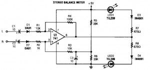
The simplest stereo balance meter circuit schematic available on the internet! When Left and Right signals are equal, no output is present from U1 and pin 6 is at a steady 4.5V. Unbalanced audio causes the LEDs to vary in brightness, which causes a difference that corresponds to unbalanced between channels.
Stereo balance meter circuit diagram
(View)
View full Circuit Diagram | Comments | Reading(0)
Crystal tester
Published:2012/10/11 2:32:00 Author:muriel | Keyword: Crystal tester
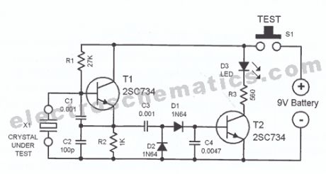
The idea for this crystal tester circuit sprung out of the need of testing a large number of oscillator crystals lying unused in a big hobby box. testing the crystals one by one without the appropriate device would have been very slow and a time consuming task. Commercial crystal testers are however very expensive, that is why this simple electronic crystal tester was born.The transistor T1 and the crystal to be tested together makes a complete crystal oscillator. The capacitors C1 and C2 works as a capacitive voltage divider that is connected to the transistor T1. If the crystal being tested is intact, the circuit oscillates. The sine wave oscillation voltage is fed to the rectifier circuit (d1, D2) and filtered by capacitor C4. With an intact crystal, the DC voltage at the base of the transistor T2 is high enough to cause the transistor to conduct. The LED lights up signalling that the crystal is good.The electronic circuit cand be used to test crystals with frequencies from 100kHz up to 30MHz. The current consumption is low: around 25mA.
Crystal Tester Circuit Diagram
(View)
View full Circuit Diagram | Comments | Reading(0)
Loudspeaker peak indicator
Published:2012/10/11 2:32:00 Author:muriel | Keyword: Loudspeaker, peak indicator
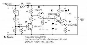
Modern loudspeakers boxes are relatively insensitive to overdriving signals, however it is still important to limit the power driving it to avoid clipping of the audio signal. A broken sound from an overdriven loudspeaker is not only annoying to the the ears but also the loudspeaker itself can be damaged by the continous uncontrolled signal peaks.
This peak indicator circuit is very useful aid in detecting the driving limits of a loudspeaker system. It can e directly connected to the existing speaker wirings and needs no extra power. It can detect very short voltage overswings and therefore provides reliable means of determing the driving limits of a loudspeaker.
The threshold of the peak indicator can be set for speakers ranging from around 15 watts to 125 watts with 8 ohms impedance. For 4 ohms speakers, the indicator can be set for 30 watts up to 250 watts. By testing speakers, occasional blinking of the LED does not mean danger but when the LED blinks very often then it is advisable to reduce the volume of the amplifier.
Loudspeaker peak indicator circuit diagram
The circuit operates this way: During operation the signal charges C2 through R1 and D1. In standby periods, all transistors are turned off and no current flows through the LED. A sample of the signal flows through P1 and enters T1. P1 controls the threshold level of T1. Once the signal sample exceeds the threshold lvel, T1 and T2 switch on and charges C1 as a result; T1 conducts amd switches T4 on.
When signal goes down, T1 and T2 turn off but since C1 discharges slowly T3 and T4 remain conducting for about one second longer causing the LED to also light up longer. This tehnique has the advantage of indicating short time signal overswings which are normally not detectable.
In constructing this peak indicator circuit it is advisable to use high luminance LEDs with a diameter of not less than 3mm.
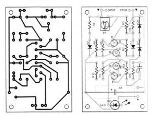
Peak indicator PCB and parts
(View)
View full Circuit Diagram | Comments | Reading(2060)
Lightning detector circuit
Published:2012/10/11 2:29:00 Author:muriel | Keyword: Lightning detector
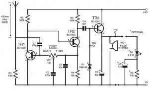
This DIY lightning detector circuit is a very sensitive static electricity detector that can provide an early warning of approaching storms from inter-cloud discharge well before an earth-to-sky return strike takes place. An aerial (antenna) formed of a short length of wire detects storms within a two mile radius.The circuit emits an audible warning tone from a piezo buzzer, or flashes an LED for each discharge detected, giving you advance warning of impendig storms so that precautions may be observed. The primary feature in the lighting detector is the circuit’s ability to be set close to self-oscillation, with its relaxation optimised via the bias resistor values shown in the circuit diagram. The oscillator is dc coupled and feedback is routed through the collector of TR1 to the base of TR2, while the overall loop gain is set with the multiturn(12, 18 or 22) preset VR1.
Lightning detector setting upTo set up the lightning sensor, adjust preset VR1 for oscillation by monitoring test point TP1, which should be at roughly 7volts peak-to-peak. Test point TP2 should be at +6V dc. Now readjust VR1 back slightly to stop oscillation; use a screwdriver to touch the aerial-side of C1 several times; the alarm should sound for 1 or 2 seconds then stop. If it continues, make a very small adjustment back and recheck. The other method is to electrostatically charge a plastic ruler and then draw your finger close to discharge, about two meter away from the aerial.
Lightning detector schematic
(View)
View full Circuit Diagram | Comments | Reading(2912)
Remote audio level indicator
Published:2012/10/11 2:28:00 Author:muriel | Keyword: Remote, audio, level indicator
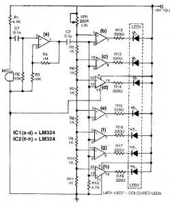
The normal level-indicator circuits which are available in the market require connections to be made to the output of the player, which may not be easily accessible. The audio level indicator circuit described here removes this restriction as it may be placed close to the player’s speakers and yet the desired effect can be realised. As shown in the circuit, signals are picked up by the condenser microphone, which get further amplified by the noninverting amplifier built around one of the four op-amps of LM324. The remaining three, along with four op-amps of the second LM324, are used as seven comparators to work as the level detector, giving seven output levels through seven coloured LEDs.
The sensitivity of the audio level indicator circuit may be improved by varying the 220k potentiometer. If a fine adjustment is desired, a 4.7-kilohm potentiometer may be connected in series resistors with the 220k potentiometer.
Remote audio level indicator circuit diagram
(View)
View full Circuit Diagram | Comments | Reading(1655)
Simple metal detector circuit
Published:2012/10/11 2:28:00 Author:muriel | Keyword: Simple, metal detector
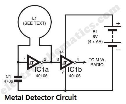
The metal detector circuit shown here must represent the limits of simplicity for a metal detector, yet the design works surprisingly well. It uses just one 40106 hex Schmitt inverter IC, a capacitor and a search coil – and of course the batteries. A lead from IC1b pin 4 needs to be attached to a medium wave radio aerial, or it should be wrapped around the radio. It can be used even like those hand held metal detectors. As shown, the metal detector gives a respectable range for beat frequency operation (bfo) up to 90mm for a bottle-top. In fact, for the ultimate in simplicity, capacitor C1 may be omitted. In this way the author achieved am amazing 150mm range for the bottle-top. However, with the frequency then being raised to more than 4MHz, instability becomes a significant problem.
As shown, the circuit oscillates at around 230kHz. One may also experiment with the frequency by changing the value of C1. A Faraday shield may be added to reduce ground effect and capacitive coupling, and this is wired to 0V.
Since the inductor resists rapid changes voltage, the charging of C1 is slightly delayed as the logic level at IC1a pin 2 changes. This sets up a rapid oscillation, which is picked up by a MW radio. Any changes in the inductance of the search coil (through the presence of metal) bring about a change to the oscillator frequency. Although 230kHz is out of range of the Medium Wave band, an MW radio will clearly pick up harmonics of this frequency.
Metal detector calibrationThe making of search coil L1 allows a lot of room for error and is far from critical. The author used seventy turns 30 s.w.g. (0,315mm) enamelled copper wire on a 120mm diameter former.The metal detector is set up by tuning the MW radio to pick up a whistle. Not every such harmonic works well, and the most suitable one needs to be found. The presence of metal will clearly change the tone of the whistle.
Metal detector faqThis is not an industrial or security metal detector and is not even close to loma or eriez metal detection products. It’s just a portable but not a hand held metal detector.
Metal Detector circuit diagram
(View)
View full Circuit Diagram | Comments | Reading(3238)
| Pages:18/101 1234567891011121314151617181920Under 20 |
Circuit Categories
power supply circuit
Amplifier Circuit
Basic Circuit
LED and Light Circuit
Sensor Circuit
Signal Processing
Electrical Equipment Circuit
Control Circuit
Remote Control Circuit
A/D-D/A Converter Circuit
Audio Circuit
Measuring and Test Circuit
Communication Circuit
Computer-Related Circuit
555 Circuit
Automotive Circuit
Repairing Circuit