
Measuring and Test Circuit
Index 2
Multi Wire Cable Testers
Published:2013/7/24 20:26:00 Author:muriel | Keyword: Multi Wire, Cable Testers
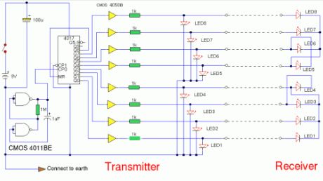
A multi wire cable tester with a separate LED for each wire. Will show open circuits, short circuits, reversals, earth faults, continuity and all with four IC's. Designed initially for my intercom, but can be used with alarm wiring, CAT 5 cables and more.
Circuit Notes:Please note that for clarity this circuit has been drawn without showing power supplies to the CMOS 4011 and CMOS 4050 IC's. The positive battery terminal connects to Pin 14 of each IC and negative to Pin 7. The CMOS 4017 uses Pin 16 and Pin 8 respectively. Note also that as the CMOS 4050 is only a hex buffer, you need 8 gates so two 4050's are required, the unused inputs are connected to ground (battery negative terminal).
Circuit Description:The circuit comprises transmitter and receiver, the cable under test linking the two. The transmitter is nothing more than a LED chaser the 4011 IC is wired as astable and clocks a 4017 decade counter divider. The 4017 is arranged so that on the 9th pulse, the count is reset. Each LED will light sequentially from LED 1 to LED 8 then back to LED 1 etc. As the 4017 has limited driving capabilities, then each output is buffered by a 4050. This provides sufficient current boost for long cables and the transmitter and receiver LED's. The receiver is simply 8 LED's with a common wire...read on. (View)
View full Circuit Diagram | Comments | Reading(1908)
MILLIGAUSS METER
Published:2013/7/24 20:25:00 Author:muriel | Keyword: MILLIGAUSS METER
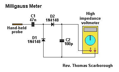
The circuit of Fig.1 provides an easy yet reliable way to detect the intensity of a.c. (or e.l.f.) fields around the home or workplace. It is doubly effective because it does not merely detect the electromagnetic radiation emitted by electrical appliances, but the electromagnetic energy actually absorbed by the body.
The circuit in Fig.1 is a standard charge pump which is charged by the alternating eddy currents induced in the human body by a.c. fields. C1 charges virtually instantly, and is read by a digital (or high impedance) voltmeter.To obtain a very rough translation from millivolts to milligauss (the unit of magnetic field strength), divide the millivolts reading by four. For example, 1000mV will yield 250 milligauss. A rough guide to the readings follows:Up to 3 milligauss - Low electromagnetic radiation25 milligauss - Significant electromagnetic radiation100 milligauss - High electromagnetic radiation250 milligauss - Maximum risk exposureDetrimental effects have been reported at doses as low as 3 milligauss, and a series of studies since the 1970's has shown that sustained exposure to high e.l.f. doses heightens the risk of certain cancers and miscarriage.Readings are taken while holding the probe in one hand. The closest proximity to the electromagnetic source does not necessarily give the highest reading, probably because the induced currents in the body remain localised at close proximity.
The SensorIs any piece of metal (e.g. a short stub of copper piping, even a short piece of fencing wire) that makes good contact with the hand. (View)
View full Circuit Diagram | Comments | Reading(1576)
Field-strength meter
Published:2013/7/24 20:25:00 Author:muriel | Keyword: Field-strength meter
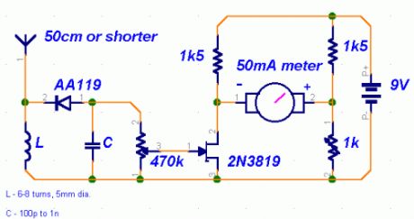
Original source:I saw this circuit in an old issue of 73 Radio Electronics . I built it, but it didn't work well, so I changed a few components to get better sensitivity.
Description:This is a very straightforward circuit. The first stage acts as a crystal receiver. Use a germanium detector diode (like 1N34, but AA119 is much more common in Europe), a silicon one won't do. The frequency is determined by L and C. For the FM band and VHF, wind a coil 5mm in diameter, 6-8 turns of coated wire 1mm thick. You can always vary the frequency by spacing the turns a bit looser or tighter. C is much less critical. Something around 100p is preferable, though.The second stage is based around the versatile 2N3819 JFET high-impedance amplifier. With the 470k potentiometer you can adjust sensitivity of the circuit. The trimmer is used to zero the meter. Use any old 50mA or slightly smaller ammeter from the junk box.
Problems:You can't expect great performance from such a simple detector-based meter. Sensitivity is just adequate enough to get a basic idea of the power that your transmitter is capable of.
Possible uses:Use the field-strength meter to find out when a transmitter is operating at optimal power. It can be very handy when aligning stages (like in case of the 4W transmitter) or experimenting with different antennas.
(View)
View full Circuit Diagram | Comments | Reading(0)
Linear Resistance Meter
Published:2013/7/24 20:24:00 Author:muriel | Keyword: Linear Resistance Meter
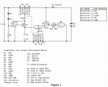
Most analogue multimeters are capable of measuring resistance over quite a wide range of values, but are rather inconvenient in use due to the reverse reading scale which is also non-linear. This can also give poor accuracy due to cramping of the scale that occurs at the high value end of each range. This resistance meter has 5 ranges and it has a forward reading linear scale on each range.The full-scale values of the 5 ranges are 1K, 10K, 100K, 1M &10M respectively and the unit is therefore capable of reasonably accurate measurements from a few tens of ohms to ten Megohms.
The CircuitMost linear scale resistance meters including the present design, work on the principle that if a resistance is fed from a constant current source the voltage developed across that resistance is proportional to its value. For example, if a 1K resistor is fed from a 1 mA current source from Ohm’s Law it can be calculated that 1 volt will be developed across the resistor (1000 Ohms divided by 0.001 amps = 1 volt). Using the same current and resistance values of 100 ohms and 10K gives voltages of 0.1volts (100 ohms / 0.001amps = 0.1volts) and 10 volts (10000 ohms / 0.001amps = 10 volts).Thus the voltage developed across the resistor is indeed proportional to its value, and a voltmeter used to measure this voltage can in fact be calibrated in resistance, and will have the desired forward reading linear scale. One slight complication is that the voltmeter must not take a significant current or this will alter the current fed to the test resistor and impair linearity. It is therefore necessary to use a high impedance voltmeter circuit.The full circuit diagram of the Linear Resistance Meter is given in Figure 1. The constant current generator is based on IC1a and Q1. R1, D1 and D2 form a simple form a simple voltage regulator circuit, which feeds a potential of just over 1.2 volts to the non-inverting input of IC1a. There is 100% negative feedback from the emitter of Q1 to the inverting input of IC1a so that Q1’s emitter is stabilised at the same potential as IC1a’s non-inverting input. In other words it is stabilised a little over 1.2 volts below the positive supply rail potential. S3a gives 5 switched emitter resistances for Q1, and therefore 5 switched emitter currents. S3b provides 5 reference resistors across T1 & T2 via S2 to set full-scale deflection on each range using VR1.As the emitter and collector currents of a high gain transistor such as a BC179 device used in the Q1 are virtually identical, this also gives 5 switched collector currents. By having 5 output currents, and the current reduced by a factor of 10 each time S3a is moved one step in a clockwise direction, the 5 required measuring ranges are obtained. R2 to R6 must be close tolerance types to ensure good accuracy on all ranges. The high impedance voltmeter section uses IC1b with 100% negative feedback from the output to the inverting input so that there is unity voltage gain from the non-inverting input to the output. The output of IC1b drives a simple voltmeter circuit using VR1 and M1, and the former is adjusted to give the correct full-scale resistance values.The CA3240E device used for IC1 is a dual op-amp having a MOS input stage and a class A output stage. These enable the device to operate with the inputs and outputs right down to the negative supply rail voltage. This is a very helpful feature in many circuits, including the present one as it enables a single supply rail to be used where a dual balanced supply would otherwise be needed. In many applications the negative supply is needed simply in order to permit the output of the op-amp to reach the 0volt rail. In applications of this type the CA3240E device normally enables the negative supply to be dispensed with.As the CA3240E has a MOS input stage for each section the input impedance is very high (about 1.5 million Megohms!) and obviously no significant input current flows into the device. This, together with the high quality of the constant current source, and the practically non-existent distortion through IC1b due to the high feedback level gives this circuit excellent linearity.With no resistor connected across T1 & T2 M1 will be taken beyond full-scale deflection and overloaded by about 100 or 200%. This is unlikely to damage the meter, but to be on the safe side a push-to-test on/off switch (S1) is used. Thus the power is only applied to the circuit when a test resistor is connected to the unit, and prolonged meter overloads are thus avoided.A small (PP3 size) 9 volt battery is a suitable power source for this project which has a current consumption of around 5mA and does not require a stabilised supply.
Photos showing inside and outside of the completed Linear Resistance Meter. (View)
View full Circuit Diagram | Comments | Reading(2669)
Digital Remote Thermometers
Published:2013/7/23 21:19:00 Author:muriel | Keyword: Digital Remote Thermometers
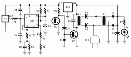
Transmitter parts:R1,R3 100K 1/4W ResistorsR2 47R 1/4W ResistorR4 5K 1/2W Trimmer CermetR5 12K 1/4W ResistorR6 10K 1/4W ResistorR7 6K8 1/4W ResistorR8,R9 1K 1/4W ResistorsC1 220nF 63V Polyester CapacitorC2 10nF 63V Polyester CapacitorC3 1µF 63V Polyester CapacitorC4,C6 1nF 63V Polyester CapacitorsC5 2n2 63V Polyester CapacitorC7,C8 47nF 400V Polyester CapacitorsC9 1000µF 25V Electrolytic CapacitorD1 1N4148 75V 150mA DiodeD2,D3 1N4002 100V 1A DiodesD4 5mm. Red LEDIC1 LM35 Linear temperature sensor ICIC2 LM331 Voltage-frequency converter ICIC3 78L06 6V 100mA Voltage regulator ICQ1 BC238 25V 100mA NPN TransistorQ2 BD139 80V 1.5A NPN TransistorL1 Primary (Connected to Q2 Collector): 100 turnsSecondary: 10 turnsWire diameter: O.2mm. enameledPlastic former with ferrite core. Outer diameter: 4mm. T1 220V Primary, 12+12V Secondary 3VA Mains transformerPL1 Male Mains plug & cable (View)
View full Circuit Diagram | Comments | Reading(1383)
Mosfet TESTER
Published:2013/7/23 21:19:00 Author:muriel | Keyword: Mosfet TESTER
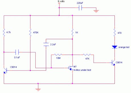
This is a variation on the astable multivibrator. Circuit was recently developed to test for N-mosfets(the power kind e.g irf830)I don’t claim circuit can test all bad mosfets or all fault mosfet conditions. If mosfet is working it will operate in the astable multivibrator circuit causing the Led to flash.A bad mosfet will not cause the LED to flash.Below is the circuit diagram, the other half of the astable utilizes an npn transistor to make the circuit cheap.Almost any npn transistor will work in this circuit.The npn transistor to the right is used as a common emitter buffer that also drives the led as it receives pulses from the mosfet drain. (View)
View full Circuit Diagram | Comments | Reading(1872)
Continuity Tester
Published:2013/7/23 21:18:00 Author:muriel | Keyword: Continuity Tester
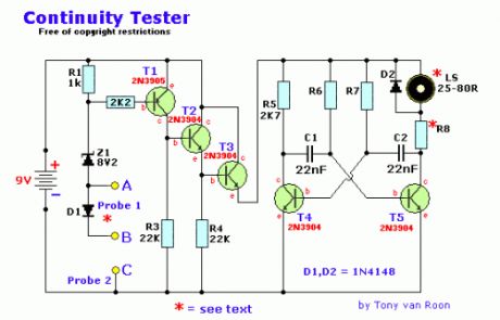
PartsR1 1K R2 2K2 R3,R4 22K R5 2K7 R6,R7 56K R8 *See text C1,C2 22nF D1,D2 1N4148Z1 8V2, 1/4 wattT1 2N3905 (PNP)T2,3,4,5 2N3904 (NPN)9volt Alkaline batterysuitable loudspeakerhousing & probes
An on-off switch is unnecessary. D1 is used when the batteryis brand-new and giving over the nominal 9volt, T1, T2 and T3 acting as the switch for supplying power to the multivibrator.
Design Considerations:Several simple circuits were tried -- a lamp, battery and probes still demanded the attention of the eyes; replacing the lamp with a buzzer was more successful but needed some three to four volts and gave no indication of a series semiconductor junction if the polarity was correct while the current flow was large enough to damage the more delicate devices within the circuit under test. An extension of the principle to operate an astable (multivibrator) type of oscillator gave good audibility but would operate from zero through to several thousands of ohms and so was too general an indication.A set of specification was becoming apparent; (1) probe current to be small; (2) probe voltage to be as low as possible, preferable less than 0.3V to avoid seeing germanium or silicon junctions as a continuous circuit; (3) no on/off switch to be used.The above circuit was the result and several have been designed and are earning their keep for both heavy electricians and electronic technicians.
(View)
View full Circuit Diagram | Comments | Reading(0)
Transistor Testers
Published:2013/7/23 21:17:00 Author:muriel | Keyword: Transistor Testers
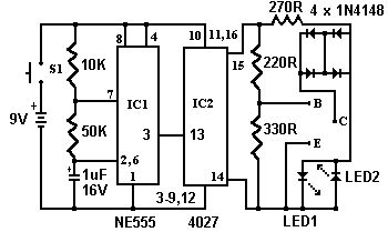
This simple circuit has helped me out on many occasions. It is able to check transistors, in the circuit, down to 40 ohms across the collector-base or base-emitter junctions. It can also check the output power transistors on amplifier circuits.Circuit operation is as follows. The 555 timer ( IC1 ) is set up as a 12hz multi vibrator. The output on pin 3 drives the 4027 flip-flop (IC2). This flip-flop divides the input frequency by two and delivers complementary voltage outputs to pin 15 and 14. The outputs are connected to LED1 and LED2 through the current limiting resistor R3. The LED's are arranged so that when the polarity across the circuit is one way only one LED will light and when the polarity reverses the other LED will light, therefore when no transistor is connected to the tester the LED's will alternately flash. The IC2 outputs are also connected to resistors R4 and R5 with the junction of these two resistors connected to the base of the transistor being tested. With a good transistor connected to the tester, the transistor will turn on and produce a short across the LED pair. If a good NPN transistor is connected then LED1 will flash by itself and if a good PNP transistor is connected then LED2 will flash by itself. If the transistor is open both LED's will flash and if the transistor is shorted then neither LED will flash.
(View)
View full Circuit Diagram | Comments | Reading(1353)
Capacitance Meter
Published:2013/7/23 21:17:00 Author:muriel | Keyword: Capacitance Meter
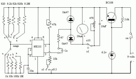
Position Range a 1 ufb 100 nfc 10 nfd 1 nfe 100 pfUse X10 switch to measure up 10uf.Use X0.5 switch for better readings on low values.
This project is more complex than the others described earlier. However, when finished, you will have an instrument capable of measuring all but the largest capacitors used in radio circuits. Unlike variable resistors, most variable capacitors are not marked with their values. As well, the markings of capacitors from salvaged equipment often rub off. By being able to measure these unmarked components, this project will prove useful to the constructor, vintage radio enthusiast or antenna experimenter.The common 555 timer IC forms the heart of the circuit (Figure Three). Its function is to charge the unknown capacitor (Cx) to a fixed voltage. The capacitor is then discharged into the meter circuit. The meter measures the current being drawn through the 47 ohm resistor. The 555 repeats the process several times a second, so that the meter needle remains steady.The deflection on the meter is directly proportional to the value of the unknown capacitor. This means that the scale is linear, like the voltage and current ranges on an analogue multimeter.The meter has five ranges, from 100pF to 1uF, selected by a five position two pole switch. In addition, there is a x10 switch for measuring higher values and a divide-by-two facility to allow a better indication on the meter where the capacitor being measured is just above 100, 1000pF, 0.01, 0.1 or 1 uF.Component values are critical. For best accuracy, it is desirable that the nine resistors wired to the Range switch have a 2% tolerance. If 0A47 diodes are not available, try OA91 or OA95 germanium diodes instead. Construct the meter in a plastic box; one that is about the size of your multimeter but deeper is ideal. The meter movement should as large as your budget allows; you will be using it to indicate exact values. A round 70mm-diameter movement salvaged from a piece of electronic equipment was used in the prototype. The meter you buy will have a scale of 0 to 50 microamps. This scale needs to be converted to read 0 to 100 (ie 20, 40, 60, 80, 100 instead of 10, 20, 30, 40, 50). Use of white correction fluid or small pieces of paper will help here.The components can be mounted on a piece of matrix board or printed circuit board. Use a socket for the IC should replacement ever be needed. Keep wires short to minimise stray capacitance; stray capacitance reduces accuracy.Calibrating the completed meter can be done in conjunction with a ready-built capacitance meter. Failing this, a selection of capacitors of known value, as measured on a laboratory meter, could be used. If neither of these options are available, simply buy several capacitors of the same value and use the one which is nearest the average as your standard reference. Use several standards to verify accuracy on all ranges.To calibrate, disable both the x10 and divide-by-two functions (ie both switches open). Then connect one of your reference capacitors and switch to an appropriate range. Vary the setting of the 47k trimpot until the meter is reading the exact value of the capacitor. Then switch in the divide-by-two function. This should change the reading on the meter. Adjust the 10k trimpot so that the needle shows exactly twice the original reading. For example, if you used a 0.01 uF reference, and the meter read 10 on the 0.1 uF range, it should now read 20. Now switch out the divide-by-two function.If you are not doing so already, change to a reference with a value equal to one of the ranges (eg 1000pF, 0.01uF, 0.1uF etc). Switch to the range equal to that value (ie the meter reads full-scale (100) when that capacitor is being measured. Switching in the x10 function should cause the meter indication to drop significantly. Adjust the 470 ohm trimpot so that the meter reads 10. Move down one range (eg from 0.01uF to 1000pF). The meter should read 100 again. If it does not, vary the 470 ohm trimpot until it does. That completes the calibration of the capacitance meter. Now try measuring other components to confirm that the measurements are reasonable.With care, an accuracy of five percent or better should be possible on most ranges.
(View)
View full Circuit Diagram | Comments | Reading(0)
Digital Radar Speedometers
Published:2013/7/23 21:16:00 Author:muriel | Keyword: Digital Radar Speedometers
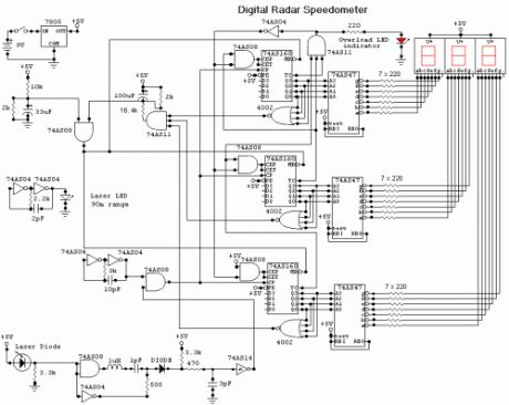
This circuit is a Digital Radar Speedometer. It allows us to evaluate the speed of any object moving, especially cars and other vehicles. The speed is calculated in kilometers per hour (KPH). Its display has three digits. This radar works with the laser reflexion. It sends laser radiation to the object and this object reflects the laser radiation to the radar. To evaluate the speed of a vehicle, we must be in front of it. In other words, the vehicle must come in our direction. The front of the radar must point the front of the vehicle. The radar has the shape of a pistol. In this radar, it has a laser LED and a laser diode. Both have a lens.The laser LED can send a spot of light to a distance of 90 m (295 ft). It's very important that the distance range of the laser LED is 90 m, if not, the speed will not be calculated properly. The laser diode, which receives the light signal by the laser LED, must be able to detect the light which is same color as that emitted by the laser LED. The laser diode and the laser LED must be placed one beside the other. They are protected by a tinted pane. They must be placed at the front of the radar and point the outside. The radar is powered by a 9V battery and it has a SPST switch to control its power state.The display, or the speed indicator, is placed at the rear of the radar, just on the right of the overload LED indicator. All the logic components of the circuit must be of the 74AS series and TTL type. Because they have short time of response (less than 1.7 ns) and have high frequency supports (more than 200 MHz). The radar can evaluate the speed of an object moving between 0 to 999 km/h. After this speed, the overload LED indicator will turn on and the 999 will still displayed. The radar displays the speed during 3 seconds, after this time, it displays zero (0).
(View)
View full Circuit Diagram | Comments | Reading(1964)
Led display digital Voltmeter
Published:2013/7/23 21:14:00 Author:muriel | Keyword: Led display, digital Voltmeter
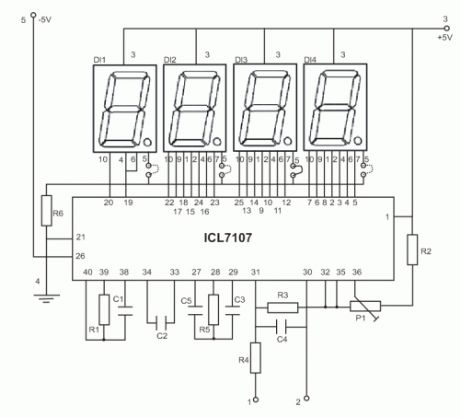
This is an easy to build, but nevertheless very accurate and useful digital voltmeter. It has been designed as a panel meter and can be used in DC power supplies or anywhere else it is necessary to have an accurate indication of the voltage present. The circuit employs the ADC (Analogue to Digital Converter) I.C. CL7107 made by INTERSIL. This IC incorporates in a 40 pin case all the circuitry necessary to convert an analogue signal to digital and can drive a series of four seven segment LED displays directly. The circuits built into the IC are an analogue to digital converter, a comparator, a clock, a decoder and a seven segment LED display driver. The circuit as it is described here can display any DC voltage in the range of 0-1999 Volts.
Technical Specifications - CharacteristicsSupply Voltage: ............. +/- 5 V (Symmetrical)Power requirements: ..... 200 mA (maximum)Measuring range: .......... +/- 0-1,999 VDC in four rangesAccuracy: ....................... 0.1 %FEATURES- Small size- Easy construction- Low cost.- Simple adjustment.- Easy to read from a distance.- Few external components.
How it WorksIn order to understand the principle of operation of the circuit it is necessary to explain how the ADC IC works. This IC has the following very important features:- Great accuracy.- It is not affected by noise.- No need for a sample and hold circuit.- It has a built-in clock.- It has no need for high accuracy external components.
(View)
View full Circuit Diagram | Comments | Reading(2323)
Digital Voltmeter
Published:2013/7/23 21:13:00 Author:muriel | Keyword: Digital Voltmeter
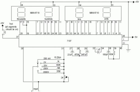
The ICL7107 is a 3 1/2 digit LED A/D convertor. It contains an internal voltage reference, high isolation analog switches, sequential control logic, and the display drivers. The auto-zero adjust ensures zero reading for 0 volts input.
(View)
View full Circuit Diagram | Comments | Reading(2057)
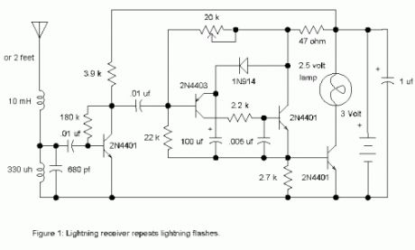
Lightning Detector
Published:2013/7/18 20:55:00 Author:muriel | Keyword: Lightning Detector
View full Circuit Diagram | Comments | Reading(0)
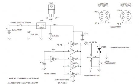
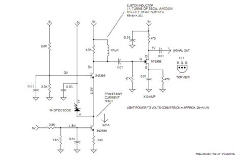
20MHz VCSEL 3mW LASER TEST CIRCUITS
Published:2013/7/15 0:43:00 Author:muriel | Keyword: 20MHz, VCSEL, 3mW , LASER TEST CIRCUITS
View full Circuit Diagram | Comments | Reading(1475)
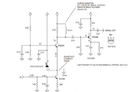
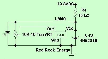
10MHz TO 20MHz LASER LIGHT DETECTORS
Published:2013/7/15 0:42:00 Author:muriel | Keyword: 10MHz TO 20MHz, LASER LIGHT, DETECTORS
View full Circuit Diagram | Comments | Reading(1292)
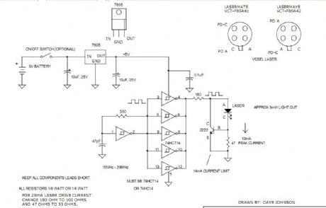
20MHz VCSEL 3mW LASER TEST CIRCUIT
Published:2013/7/11 22:24:00 Author:muriel | Keyword: 20MHz , VCSEL , 3mW , LASER TEST CIRCUIT
View full Circuit Diagram | Comments | Reading(1195)
10MHz TO 20MHz LASER LIGHT DETECTOR
Published:2013/7/11 22:23:00 Author:muriel | Keyword: 10MHz TO 20MHz, LASER LIGHT DETECTOR
View full Circuit Diagram | Comments | Reading(1088)
High-impedance voltmeter 2
Published:2013/7/11 22:20:00 Author:muriel | Keyword: High-impedance voltmeter
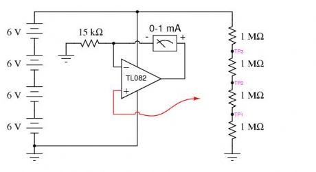
View full Circuit Diagram | Comments | Reading(1557)
High-impedance voltmeter
Published:2013/7/11 22:19:00 Author:muriel | Keyword: High-impedance voltmeter
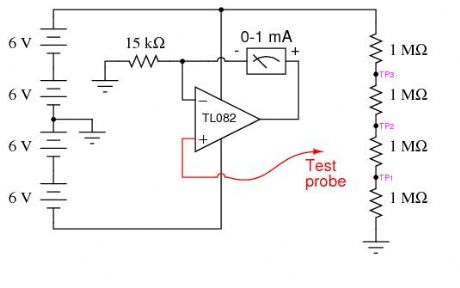
View full Circuit Diagram | Comments | Reading(0)
Temporary Test Circuit
Published:2013/7/5 1:53:00 Author:muriel | Keyword: Temporary Test Circuit
View full Circuit Diagram | Comments | Reading(1286)
| Pages:2/101 1234567891011121314151617181920Under 20 |
Circuit Categories
power supply circuit
Amplifier Circuit
Basic Circuit
LED and Light Circuit
Sensor Circuit
Signal Processing
Electrical Equipment Circuit
Control Circuit
Remote Control Circuit
A/D-D/A Converter Circuit
Audio Circuit
Measuring and Test Circuit
Communication Circuit
Computer-Related Circuit
555 Circuit
Automotive Circuit
Repairing Circuit