
Measuring and Test Circuit
Index 6
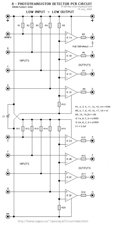
Non Inverting 8 - Photo-Detector PCB Schematic
Published:2013/5/22 21:54:00 Author:muriel | Keyword: Non Inverting 8, Photo-Detector, PCB Schematic
View full Circuit Diagram | Comments | Reading(810)
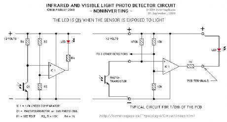
Basic Non Inverting Detector Circuit
Published:2013/5/22 21:53:00 Author:muriel | Keyword: Basic Non Inverting Detector Circuit
View full Circuit Diagram | Comments | Reading(982)
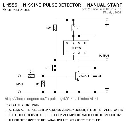
Manual Start - Missing Pulse Detector
Published:2013/5/22 21:36:00 Author:muriel | Keyword: Manual Start , Missing Pulse Detector
View full Circuit Diagram | Comments | Reading(1888)
Latching Output - Missing Pulse Detector
Published:2013/5/22 21:36:00 Author:muriel | Keyword: Latching Output, Missing Pulse Detector

View full Circuit Diagram | Comments | Reading(2277)
Steady Output - Missing Pulse Detectors - Two Timers
Published:2013/5/22 21:35:00 Author:muriel | Keyword: Steady Output , Missing Pulse Detectors , Two Timers
View full Circuit Diagram | Comments | Reading(1246)
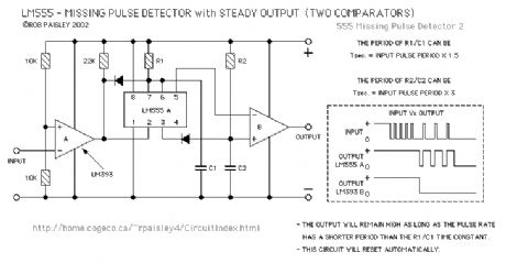
Steady Output - Missing Pulse Detectors - Two Comparators
Published:2013/5/22 21:35:00 Author:muriel | Keyword: Steady Output , Missing Pulse Detectors , Two Comparators

View full Circuit Diagram | Comments | Reading(1030)
Basic - Missing Pulse Detectors
Published:2013/5/22 21:34:00 Author:muriel | Keyword: Basic - Missing Pulse Detectors
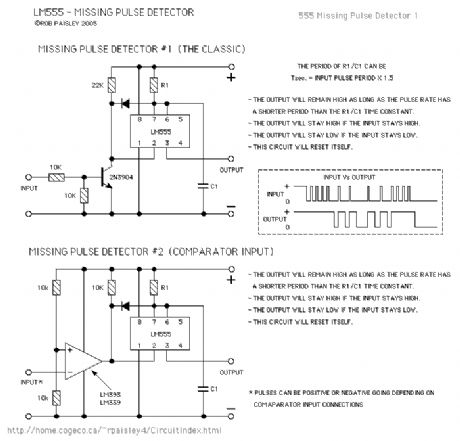
View full Circuit Diagram | Comments | Reading(1426)
Frequency and Capacitance meter
Published:2013/5/14 22:46:00 Author:muriel | Keyword: Frequency and Capacitance meter
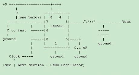
View full Circuit Diagram | Comments | Reading(1341)
Human Traffic Footstep Detector 2
Published:2013/5/14 21:58:00 Author:muriel | Keyword: Human Traffic Footstep Detector
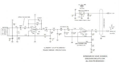
View full Circuit Diagram | Comments | Reading(1355)
GEOPHONE FOOT STOMP DETECTOR
Published:2013/5/14 21:56:00 Author:muriel | Keyword: GEOPHONE FOOT STOMP DETECTOR
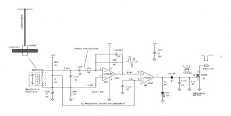
View full Circuit Diagram | Comments | Reading(2334)
Accelerometer
Published:2013/5/9 21:27:00 Author:muriel | Keyword: Accelerometer

View full Circuit Diagram | Comments | Reading(1536)
A simple handheld hygrometer
Published:2013/5/9 21:27:00 Author:muriel | Keyword: A simple handheld hygrometer
View full Circuit Diagram | Comments | Reading(1332)
An Equivalent Series Resistance Meter
Published:2013/5/9 21:26:00 Author:muriel | Keyword: Equivalent Series , Resistance Meter

View full Circuit Diagram | Comments | Reading(1556)
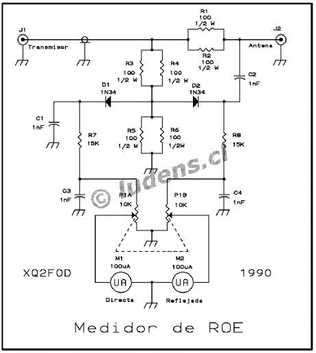
Wideband SWR meter
Published:2013/5/9 21:17:00 Author:muriel | Keyword: Wideband SWR meter
View full Circuit Diagram | Comments | Reading(1703)
ELECTRIC FIELD DETECTOR
Published:2013/5/7 21:38:00 Author:muriel | Keyword: ELECTRIC FIELD DETECTOR
The circuit will come handy when you have to follow the mains wires buried in the wall or even water pipes provided they are not too far away (2-4cm max). It will also detect a conversation on a telephone cable without actually touching it (for testing purposes only) and it works as a microphone if you keep a plastic kitchen foil between the probe tip and your mouth. The probe is just the 12mm long gate lead of the transistor. The 33M resistor should be cut short and soldered where the lead enters the transistor case. Connection to the other part of the circuit is via a standard coaxial cable of any length. The input is not protected and a pair of low leakage diodes (JPAD5) could be connected back to back between gate and ground. I did not find them necessary: I covered, with a small piece of plastic sponge, the probe tip to avoid direct contact with electrified surfaces and used a minimum of care when handling the probe. (View)
View full Circuit Diagram | Comments | Reading(2225)
SEISMIC DETECTOR
Published:2013/5/7 21:30:00 Author:muriel | Keyword: SEISMIC DETECTOR
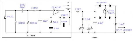
The piezoelectric element of a kitchen gas lighter is used in this simple, yet effective seismic detector. The piezo element must be placed vertically, one end solidly to ground. A 2-3 pound weight of fine gravel in a loose package should be placed on top at the other end. The high voltage lead goes to the IC, placed close to the piezo element. The whole box is acoustically and electromagnetically screened. A 3 core shielded cable brings the signal to the rest of the circuit and to the power supply (+/- 15V). The SB140 diodes are Schottky type and pin 8 (substrate) of the IC should be connected to ground. (View)
View full Circuit Diagram | Comments | Reading(1348)
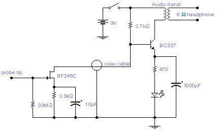
GEOMAGNETIC FIELD DETECTOR
Published:2013/5/7 21:29:00 Author:muriel | Keyword: GEOMAGNETIC FIELD DETECTOR
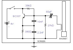
This basic oscillator will detect the Earth magnetic field. The ferrite rod and coil are taken from an old Medium Wave receiver and a small magnet is glued at one end. Tune to a medium wave commercial station until you hear a beat note. Any movement of the ferrite rod will produce an audible note that depends on the prevailing Earth magnetic field. Screening is essential. Use a plastic box padded, on the inside, with copper wires running parallel to the rod and grounded in one place only. A small hole is made in the box in order to adjust the trimmer capacitor with a plastic screwdriver. An American equivalent to the BC337 could be the 2N2369A but I did not try it out. (View)
View full Circuit Diagram | Comments | Reading(1159)
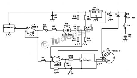
CAR BATTERY TESTER
Published:2013/5/7 21:22:00 Author:muriel | Keyword: CAR BATTERY TESTER
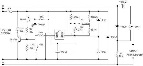
Checking the status of your car battery (accumulator) should be easier with this circuit which measures the internal resistance of the battery. Pulses generated by the 555 are used to drive a dummy load and the AC voltage which develops across the battery gives an indication of its internal resistance: the lower the voltage the healthier the battery. The AC voltage is read out by means of a digital meter connected at the output. Separate leads are used for the dummy load and for the metering circuit. They should be connected to their respective battery lugs but they should not touch each other. This avoids erroneous readings due to less than perfect contacts of the dummy load. The internal resistance depends on the battery temperature as well; this is the reason for the switch: hot means a battery (not ambient) temperature between 35 and 52 degrees Centigrade, normal is for a temperature between 16 and 34 degrees and cold is good for a temperature from -4 to 15. Beyond these ranges the reading is unreliable. The internal resistance depends also on the rated capacity of the battery. The 100 ohm potentiometer sets the battery capacity: it is rotated totally to positive for a 100Ah battery and totally to negative for a 32Ah battery. A dial with uniform markings from 32 to 100 was used in the prototype. This means we can measure internal resistance of batteries rated from 32 to 100Ah. As there are a number of smaller 12V batteries around, specially for alarm systems, a switch was introduced that, in the X1 position, will change the capacity range to 3.2 - 10Ah. The unit has six leads going out of the box: two for the dummy load, two for the metering section and two going to the digital meter. Operation is simple: set the range, temperature and battery rating, then connect the dummy load and the metering leads to the battery lugs and read the ac voltage: you should be safe if it reads below 10-12mV otherwise it is better to give the battery a good recharge and if it is still beyond 10-12mV then probably you need a new battery. A bright orange LED shows that the unit is connected and in operation. (View)
View full Circuit Diagram | Comments | Reading(4286)
MAINS FREQUENCY METER 2
Published:2013/5/7 21:19:00 Author:muriel | Keyword: MAINS FREQUENCY METER
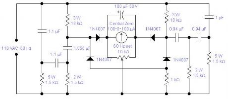
WARNING! This circuit is directly connected to the mains and should be assembled in a box which will avoid access to any of its part and care must be exercised when calibrating the unit. If you live in the States or you have a 110 VAC, 60 Hz mains, you may try the second circuit: the reported values are calculated values, I did not actually test the unit. The odd capacitors values are easily obtained with the combination of standard values: 0.94 is 2 x 0.47 in parallel, 1.056 is 1μF + 56nF in parallel and 1.1 is 1 + 0.1μF.
(View)
View full Circuit Diagram | Comments | Reading(1453)
MAINS FREQUENCY METER 1
Published:2013/5/7 21:18:00 Author:muriel | Keyword: MAINS FREQUENCY METER
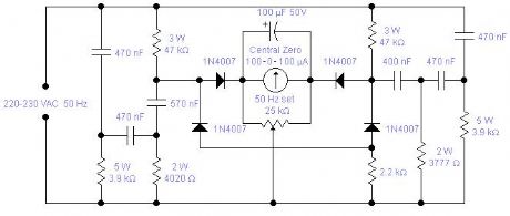
Mains frequency is pretty stable and it is unlikely that you have to measure it but if you have an emergency generator you might find this circuit useful as it will give an indication whether the generator is running too fast or too slow. Actually you can use the mains frequency to calibrate it by adjusting the 25K multiturn trimmer until it reads 0. The odd looking components values are easily obtained using standard values: 3777 is 3900 in parallel with 120KΩ, 4020 is 3900 and 120 in series, 570nF is 470nF with 100nF in parallel and 400nF is 4 x 100nF capacitors in parallel. Components should be chosen for their stability and precision. 1% tolerance would be ideal but 5% is acceptable so long as you measure them with a good meter. Capacitors should be properly rated for direct connection to the mains and resistors should have a low temperature coefficient as it will adversely affect the zero setting and change the filters response. The 100μF capacitor could be occasionally reverse biased with a voltage of 0.1-0.2 V. There is no problem for the capacitor which is generously rated. Operation is quite simple: connect it first to the mains, wait about 4-5 minutes until all resistors reach their working temperature, calibrate, and then connect to the generator. (View)
View full Circuit Diagram | Comments | Reading(1901)
| Pages:6/101 1234567891011121314151617181920Under 20 |
Circuit Categories
power supply circuit
Amplifier Circuit
Basic Circuit
LED and Light Circuit
Sensor Circuit
Signal Processing
Electrical Equipment Circuit
Control Circuit
Remote Control Circuit
A/D-D/A Converter Circuit
Audio Circuit
Measuring and Test Circuit
Communication Circuit
Computer-Related Circuit
555 Circuit
Automotive Circuit
Repairing Circuit