
Measuring and Test Circuit
Index 20
Homemade metal detector
Published:2012/9/24 4:09:00 Author:muriel | Keyword: Homemade, metal detector
This homemade metal detector circuit will help you find objects composed of materials with relatively high magnetic permeability. It is not suitable for buried coins discovery that is not sensitive enough but you can detect pirates treasures!
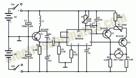
The metal detector is powered by 2 x 9V batteries, each of it charges with 15 mA. L1 detector coil is part of the sinusoidal oscillator built around transistor T1. Normally, the center frequency of the voltage controlled oscillator (VCO) from the PLL loop that is contained in IC1 is equal to the oscillation frequency of T1. This changes when entering a metallic object (ferrous or nonferrous) in the field induced by L1. S1 is a miniature 2-pole switch.Meter needle deviation is a measure of frequency change, since the direction of deviation depends on the type of material detected by the coil.The meter tool used for this homemade metal detector is zero as central, +-50µA.
Coil L1 consists of 40 turns of enamelled copper wire, wound on a plastic template with a diameter of about 10 cm. Inductance thus obtained ensure the functioning of the oscillator at a frequency approximately equal to the VCO included in the PLL loop.
Metal detector circuit schematic
Use an oscilloscope to check that pin 2 of IC1 delivers sinusoidal signal with frequency about 75 kHz. Adjust P1 so that fronts rectangular signal from pin 4 to coincide with the peaks of the sinusoidal signal from pin 2. Then, adjust P2 in order to obtain 0 on the meter. Since the neutral zero setting “runs” with the battery’s decreasing voltage it will be necessary to restore it (zero balancing) from time to time during use of the metal detector.
Related metal detector circuits?
8 Responses to “Homemade metal detector”
(View)
View full Circuit Diagram | Comments | Reading(5100)
David Moran capacitor meter project
Published:2012/9/24 4:08:00 Author:muriel | Keyword: David Moran, capacitor meter
Hi guys, I just received an email from David Moran and he sent me his capacitor meter project with pictures and a little presentation. Here are the details and schematic.
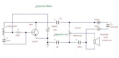
Here is the schematic of my capacitor meter I built and have used quite a bit. It will measure from zero to 0.1uf with 300pf at mid range. It is an oscillator that makes noise fed into a bridge circuit that will null out the noise when balanced. Once built, you must clip in known value capacitors and hand calibrate the dial.I built my unit into a cheap push on battery light the output can go to a small audio amp, audio input of a computer, or try a piezo speaker. The noise is rather annoying, so you may want to use a scope to view it if you must test many capacitors.
Capacitor meter schematic
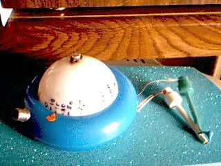
And here is a picture with the finished project:
Thank you David, you’ve done a great job!?
2 Responses to “David Moran capacitor meter project”
(View)
View full Circuit Diagram | Comments | Reading(1535)
RF Network Cable Tester
Published:2012/9/21 2:34:00 Author:Ecco | Keyword: RF Network, Cable Tester
Here is an ideal Network Cable tester to check whether RF signal is present in the Network Cable or not. It is a non contact version tester and can detect the presence of RF signal from a distance of two feet. It can be used to check all kinds of signal cables like Ethernet cable, Modem cable, Dish TV cable etc. The circuit lights an LED at the moment it accepts RF energy around the cable.The Network Cable Tester circuit has two parts. The front end has an RF detector followed by a signal amplifier. Coil L1, diode D1, capacitor C1 and resistor R1-R2 forms the signal detector section. L1 is a 0.5 mm inner diam coil made up of 10 turns of 22 SWG enameled copper wire. D1 is the high frequency Schottky signal diode. C1 decouples the signals. The signal amplifier is built using the popular BiMOS operational amplifier CA3140. It has gate protected MOSFET inputs.
The IC has low input current requirements as low as 5pA. It is a high speed device and can work between 5 to 36 volts. When the antenna (A telescopic antenna used in pocket radio) come close to the cable, coil L1 accepts the RF energy and the fast recovery diode D1 passes this energy into the inverting input of IC1 . IC is designed as an inverting amplifier with feedback. Resistor R3 determines the degree of feedback. When IC1 gets a positive pulse, its output becomes high lighting the LED. This indicates the presence of RF signal in the cable.
Network Cable Tester Circuit Diagram
BAT43 Datasheet
IC CA3140
BAT 43 Schottky Diode
?
2 Responses to “RF Network Cable Tester”
source: electroschematics.com (View)
View full Circuit Diagram | Comments | Reading(1712)
Storm Detector circuit
Published:2012/9/21 2:34:00 Author:Ecco | Keyword: Storm Detector
This storm detector circuit is very easy to build. It has a sensitive amplifier and one antenna, that togheter can detect storms at large distance. The antenna has 220 turns of enamelled copper on a square wooden frame with a side of 85 cm. The wire diameter is not so important, 0.4 mm is enough. In parallel with the end windings a capacitor is connected in order to obtain a tuned antenna on a frequency between 4 to 5 kHz. The antenna is connected through 2 twisted wires to the amplifier. The output signal can be applied to an audio amplifier or an oscilloscope in order to hear or see the signal.
Storm Detector Circuit Diagram
Storm Detector Components ListR1 = 100KΩR2 = 100KΩR3 = 1.8KΩR4 = 600ΩC1 = 10nFC2 = 10µF/25VC3 = 100µF/6.3VT1 = T2 = BC547, 548, 549?
One Response to “Storm Detector circuit”
(View)
View full Circuit Diagram | Comments | Reading(2060)
Fatigue Testing circuit
Published:2012/9/20 21:03:00 Author:Ecco | Keyword: Fatigue Testing
This fatigue testing circuit is very simple and easy to build and will determine how tired a person is. It has been discovered that the highest light frequency that a human can detect is negatively influenced by his fatigue. This circuit is based on 555 timer that is connected here as an astable multivibrator. Its output is connected to a LED that is flashing with a certain frequency.With P1 potentiometer that frequency can be adjusted between 20 and 50 Hz. The highest flashing frequency the humans can detect is somewhere between 30 and 40 flash per second but a test made by us in a early morning produced some questions like: “What LED?”.
Fatigue Tester Circuit Diagram
To make a reliable fatigue test you must adjust P1 when you are not tired. So, adjust P1 untill you just start not seeing the LED light. Leave it like that and then power up the circuit when you are tired and you will notice that the LED light has gone .
Because of the fatigue tester circuit nature, there is no wonder it has a small current consumption of just 25 mA so you can powered it up from a 9 V battery. Do not consider this to be equal to fatigue testers found on the market.?
No Responses to “Fatigue Testing circuit”
(View)
View full Circuit Diagram | Comments | Reading(1136)
Infrared detector with PID20
Published:2012/9/20 20:58:00 Author:Ecco | Keyword: Infrared detector
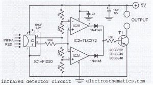
This infrared detector circuit uses a passive IR-detector component PID20. It converts heat radiation into electrical impulses. The output voltage of the PID20 increases when an object comes close to it, this object must be warmer than the surroundings.The voltage changes at the output of the IR sensor are sensed by the comparators IC2a and IC2b. Once the sensor detects an object (independent of the object’s actual temperature), one of the comparators will turn on the transistor T1. This transistor then closes the relay connected to it. A separate transistor for each comparator can be used so that the sensor will be able to determine whether the object is warmer or colder than the surroundings. The IR detector circuit consumes around 1 mA and the sensor consumes 0.2 mA.
IR detector circuit diagram
Source: electroschematics.com?
One Response to “Infrared detector with PID20”
(View)
View full Circuit Diagram | Comments | Reading(1960)
LED Component Tester with Torch
Published:2012/9/20 20:55:00 Author:Ecco | Keyword: LED Component Tester , Torch
Here is a simple tester for Hobbyists. This LED Component tester can test the integrity of electronic components from resistors to ICs before soldering. It reduces the job of testing the components using multimeter. The tester gives LED indications about the Good or Bad conditions of the components. A White LED torch is added to verify the value of the components if light is not sufficient.The circuit layout is straight forward. Two bipolar NPN transistors are used to drive two LEDs based on their base bias. When the tester is switched on through S2, Red LED lights because T2 gets base bias through R2. At the same time, Green LED remains off because the base of T1 is floating .
When a component is placed between the Probes, electrical continuity establishes and T1 gets base current through R1. When T1 conducts, Green LED turns on and Red LED turns off since the base of T2 is grounded when T1 conducts. This indicates that the component under test is good. In short Green LED lights only when a good component is connected to the probes. If the component is bad, probes will not get electrical continuity and T1 remains off. In this state only Red LED light indicating that the component is bad. Test procedure is given below.
LED Component Tester Circuit diagram
Test Procedure
1. PolarityConnect Red probe to positive track of circuit board and Black probe to test point. Circuit board under test should be ONGreen LED ON – Positive supply. Green LED OFF and Red LED ON – Negative supply or No power
2. ContinuityConnect both Red and Black probes across the test pointsGreen LED ON- Continuity. Green LED OFF and Red LED ON- No continuity
3. Resistor. 1 Ohm to 500KConnect Red and Black probes on either side of ResistorGreen LED ON- Resistor OK. Green LED OFF and Red LED ON-Resistor burned
4. Capacitor ElectrolyticRed probe to positive and Black probe to negative of capacitorGreen LED ON and gradually fades and then Red ON- Capacitor Good. Red LED always ON- Capacitor bad
5. Capacitor DiscSame as above.Probes can be connected either way round
6. LED, Diodes, Photodiodes, Infrared diodesRed probe to Anode and Black probe to CathodeGreen LED ON – Good diode and LED. Green LED OFF and Red LED ON- Diode or LED badChange the direction of Probes. If the Green LED ON diode or LED is Open
7. LDRRed and Black probes at the leads of LDRGreen LED ON and Red LED OFF. Mask with hand. Green LED turns OFF-LDR good
Probes with Crocodile Clips
?
One Response to “LED Component Tester with Torch”
Source: electroschematics.com
(View)
View full Circuit Diagram | Comments | Reading(1394)
The armature ground fault test circuit using traffic lights
Published:2012/9/19 2:35:00 Author:Ecco | Keyword: armature ground fault, test circuit , traffic lights
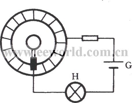
The armature is an important part of tributary electric motor and single-phase series motor, and its common faults include winding grounding, short circuit and reversed connection. These can be detected with a multimeter and megger. As shown in figure, it is a test schematic diagram with traffic light. When it is measured, the black stick of light is connected to the shaft ( ground ), red bar table is touched commutator segment. If the lamp H is not bright, it means that there is not a pathway between winding or commutator and shaft, no ground fault. If the light bulb is lit, it has existed ground fault and should be promptly repaired.
(View)
View full Circuit Diagram | Comments | Reading(1874)
Dew Detector Probe Circuit
Published:2012/9/19 21:27:00 Author:Ecco | Keyword: Dew Detector, Probe
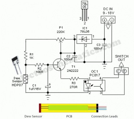
This simple and economical Dew Detector Probe circuit works on 5V dc supply. It is useful for checking the presence of dew (condensed moisture) inside sensitive electronic devices like VTR, Camera,C opier,Computer etc. The circuit utilises a ready-made dew sensor element HDP-07 (from “Hokuriku”). However, you can use any other type (carefully lifted from a discarded VTR or similar equipment) without any circuit modification.The principle of the ready made dew sensor element is based on the change in resistance of a conductive polymer in a thin film on a small ceramic substrate. As the sensing polymer wet (90 to 95% Relative Humidity), its resistance will increase drastically because the polymer expands and therefore causes a larger distance between the conductive particles. After successful construction, enclose the whole unit in a small aluminium tube as shown in the figure.This circuit has an on-board voltage regulator wired around LM78L05 (IC1). Although we can safely feed dc supply upto +35 V to this circuit, dc input in +9 to 12 V range is recommended. Similarly an opto-coupler PC817 (OC1) is used to isolate the detector circuit from the rest of the external switch/control unit. As you may noticed, this is an open-collector output which can be easily interfaced to any analogue or digital switch/control circuits like relay switches,alarm units etc.In idle state resistance of the dew sensor element is very low and thus most of the base current of transistor T1 (2N2222) finds an alternative path via dew sensor and T1 remains in cut off. Condition. When Relative Humidity (RH) exceeds and touches the 90-95% level, dew sensor element behaves almost like an open component (very high resistance), T1 is forward biased and the opto-coupler is energised. Note that the adjustment of threshold set preset pot P1 is very critical. Use theoritical & empirical methods to calibrate the detection mechanism.
Dew Sensor Circuit Schematic
Source: electroschematic.com (View)
View full Circuit Diagram | Comments | Reading(3224)
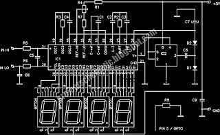
The level test circuit with CMOS NAND gate 4011 connected into inverter
Published:2012/9/16 22:53:00 Author:Ecco | Keyword: level test , CMOS NAND gate , inverter
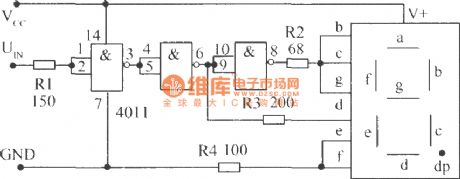
In this circuit, it can also use NOT gate to replace 4011. High level displays H, low level displays L. R2 ~ R4 play a limiting role, so the digital tube and its anode are connected to the positive power supply Vcc directly. The normally on segments e , f are grounded by R4 to reduce the drive current.
(View)
View full Circuit Diagram | Comments | Reading(2198)
LED VU Meter with LM3914N
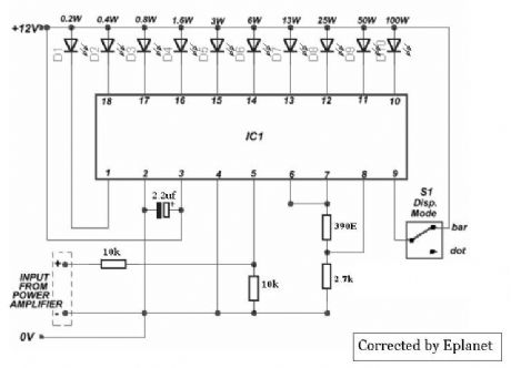
Published:2012/9/16 21:26:00 Author:Ecco | Keyword: LED, VU Meter
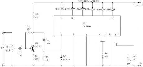
The circuit is based on an LM3914N bar graph display driver device (IC1), which can be used to drive up to ten LEDs. This is connected so that with OV12 at the input only the first LED indicator switches on. This simple peak reading VU meter circuit uses six LEDs to indi-cate six signal levels at 14, 8, 3, 0, +3, and +6dB, or any other levels having the same spacing (e.g. 17, 11, 6, 3, 0, and +3dB, if preferred). About 24mV peak to peak is needed in order to activate the highest LED indicator, so the circuit is sufficiently sensi-tive to be used with any normal item of audio equipment. (View)
View full Circuit Diagram | Comments | Reading(4129)
VU Meter with Audio Mixer circuit
Published:2012/9/16 21:25:00 Author:Ecco | Keyword: VU Meter , Audio Mixer
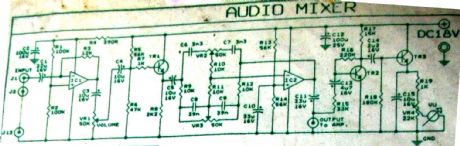
This is audio mixer circuit. The circuit is for one channel input, if you need, for example 5 channel mixer, then you need to build 5 similar circuits. (View)
View full Circuit Diagram | Comments | Reading(4462)
VU meter with LM3915
Published:2012/9/16 21:24:00 Author:Ecco | Keyword: VU meter
This nifty sound level meter is a perfect one chip replacement for the standard analog meters. It is completely solid state and will never wear out. The whole circuit is based on the LM3915 audio level IC and uses only a few external components. (View)
View full Circuit Diagram | Comments | Reading(5502)
Thermometer circuit with AD595
Published:2012/9/16 21:24:00 Author:Ecco | Keyword: Thermometer circuit
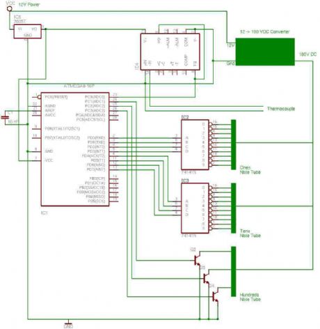
the entire circuit is comprised of integrated circuits. This makes for some easy organization when it goes to the circuit board for soldering. In addition, I used only 3 of the pins on the 3rd nixie tube for the hundreds position in the display. Since I was only using three, I decided to save a 74141 IC and just use a few high voltage transistors (MPSA42). I figure the thermometer will very unlikely be in any situation where a temperature between 0 and 399 will ever need to be displayed, and if it is, the electronics will probably not work anyways. (View)
View full Circuit Diagram | Comments | Reading(2489)
Digital Thermometer circuit up to 150°C
Published:2012/9/16 21:23:00 Author:Ecco | Keyword: Digital Thermometer, 150°C
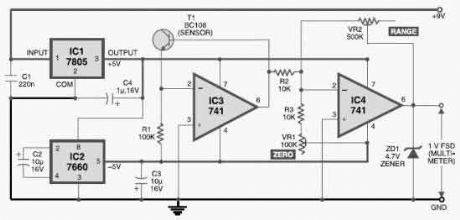
This digital thermometer circuit can measure temperatures up to 150°C with an accuracy of ±1°C. The temperature is read on a 1V full scale-deflection (FSD) moving-coil voltmeter or digital voltmeter. Operational amplifier IC 741 (IC3) provides a constant flow of current through the base-emitter junction of npn transistor BC108 (T1). The voltage across the base-emitter junction of the transistor is proportional to its temperature. (View)
View full Circuit Diagram | Comments | Reading(1489)
digital voltmeter with LED display (ICL7107)
Published:2012/9/16 20:51:00 Author:Ecco | Keyword: digital voltmeter , LED display
This is a design circuit for digital voltmeter with LED display. Itas ideal to use for measuring the output voltage of your DC power supply. It includes a 3.5-digit LED display with a negative voltage indicator. It measures DC voltages from 0 to 199.9V with a resolution of 0.1V. The voltmeter is based on single ICL7107 chip and may be fitted on a small 3cm x 7cm printed circuit board. The circuit should be supplied with a 5V voltage supply and consumes only around 25mA. (View)
View full Circuit Diagram | Comments | Reading(4605)
Metal Detector TDA 2822
Published:2012/9/13 21:17:00 Author:Ecco | Keyword: Metal Detector
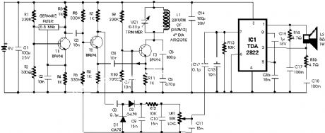
The circuit described here is that of a metal detector. The opera- tion of the circuit is based on superheterodyning principle which is commonly used in superhet receivers. The circuit utilises two RF oscillators. The frequencies of both oscillators are fixed at 5.5 MHz. The first RF oscillator comprises transistor T1 (BF 494) and a 5.5MHz ceramic filter commonly used in TV sound-IF section. The second oscillator is a Colpitts oscillator realised with the help of transistor T3 (BF494) and inductor L1 (whose construction details follow) shunted by trimmer capacitor VC1.
(View)
View full Circuit Diagram | Comments | Reading(2643)
Low cost Metal Detector
Published:2012/9/13 21:17:00 Author:Ecco | Keyword: Low cost , Metal Detector
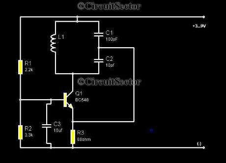
Metal detectors are usually very complicated and it may be consist of very costly components and metal detector DIY circuits are rare. However this metal detector hobby circuit can be constructed by only a few components such as BC548 and an ordinary AM radio that we usually use.
Source: NEXT.GR (View)
View full Circuit Diagram | Comments | Reading(2184)
metal detector with MC AT90S2313
Published:2012/9/13 21:16:00 Author:Ecco | Keyword: metal detector , MC
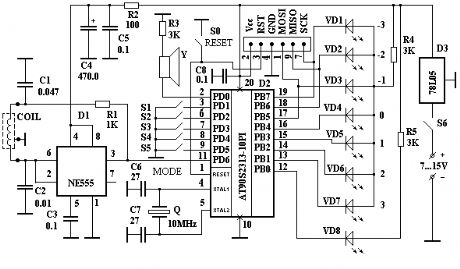
It's a simple metal detector design that has the quite good characteristics. the principle of operation which one differs from the classic schemes (BFO, transmit-receive known as two-boxes metal detector, inductive). The dynamic mode is used to find targets in interference environment. There is known from theory of signal filtration that if signal shape is determined we can construct optimal filter - the best one for extracting the signal with maximum signal/noise ratio. This filter is known as optimal matched filter.
(View)
View full Circuit Diagram | Comments | Reading(5842)
Metal detector with CD4011
Published:2012/9/13 21:16:00 Author:Ecco | Keyword: Metal detector
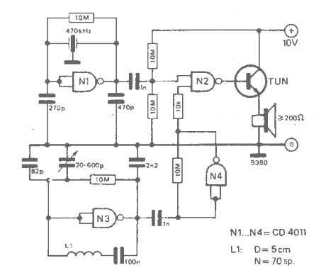
The working principle of this cheap and easy to build metal detector circuit consists in mixing two equal frequencies which causes a low-frequency interference. When one of the oscillators become unstable then the frenquency of the interference will be modified. The metal detector circuit is built with CD4011.
Source: NEXT.GR (View)
View full Circuit Diagram | Comments | Reading(3800)
| Pages:20/101 1234567891011121314151617181920Under 20 |
Circuit Categories
power supply circuit
Amplifier Circuit
Basic Circuit
LED and Light Circuit
Sensor Circuit
Signal Processing
Electrical Equipment Circuit
Control Circuit
Remote Control Circuit
A/D-D/A Converter Circuit
Audio Circuit
Measuring and Test Circuit
Communication Circuit
Computer-Related Circuit
555 Circuit
Automotive Circuit
Repairing Circuit