
Measuring and Test Circuit
Index 3
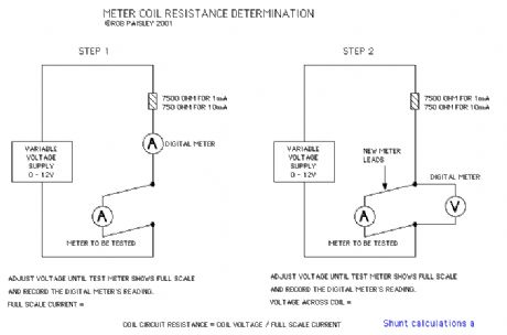
The Coil Resistance Of A Meter
Published:2013/6/25 22:42:00 Author:muriel | Keyword: The Coil Resistance , Meter
View full Circuit Diagram | Comments | Reading(1400)
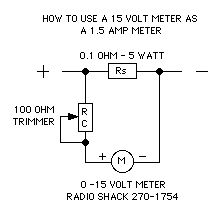
1.5 AMP Shunt Ammeter Circuit
Published:2013/6/25 22:41:00 Author:muriel | Keyword: 1.5 AMP, Shunt Ammeter Circuit
View full Circuit Diagram | Comments | Reading(1256)
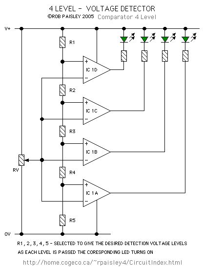
4 Level voltage Detector
Published:2013/6/25 22:40:00 Author:muriel | Keyword: 4 Level, voltage Detector
View full Circuit Diagram | Comments | Reading(3248)
Day and Night Detector Schematic
Published:2013/6/25 21:45:00 Author:muriel | Keyword: Day and Night Detector Schematic

The detector for this circuit uses a voltage comparator the same as those on the Visible and Infrared Light Detectors page at this site.
The major change is the mounting of infrared emitters mounted at ceiling height above the detectors phototransistor. (View)
View full Circuit Diagram | Comments | Reading(1216)
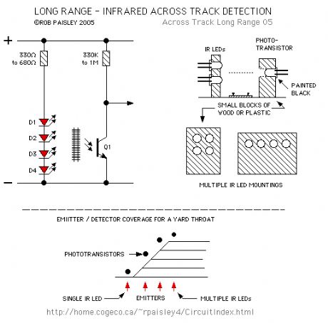
Long Range - Across The Track Detection
Published:2013/6/25 21:41:00 Author:muriel | Keyword: Long Range, Track Detection
View full Circuit Diagram | Comments | Reading(886)
Track Infrared Detectors
Published:2013/6/25 21:39:00 Author:muriel | Keyword: Track Infrared Detectors
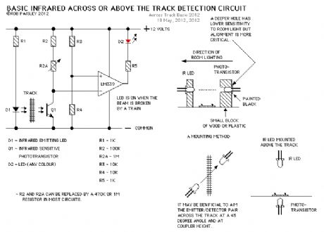
This page presents information on infrared - Above The Track and Across The Track train position detection circuits. The circuits are designed around the LM339 quad comparator chip and can use a wide assortment of matched infrared - emitter / detector pairs.
The circuit bellow is the basic voltage comparator based detector circuit using the LM339 Quad or LM393 Dual comparator ICs.
The LED will turn on when the infrared beam is broken. The value of the resistor R1 determines the sensitivity of the phototransistor Q1. In most cases a value of 1 Meg or 470K ohm with good results but every situation is different and some experimentation might be needed.
Circuit Operation - When a train breaks the infrared beam the phototransistor will conduct less current. The voltage at the MINUS input of the comparator will rise above the reference voltage at the PLUS as determined by R3 and R4. The output of the comparator to turn ON and the LED will be lit. (View)
View full Circuit Diagram | Comments | Reading(1351)
Basic Photocell Detector
Published:2013/6/21 3:16:00 Author:muriel | Keyword: Basic Photocell Detector
View full Circuit Diagram | Comments | Reading(1075)
Basic Phototransistor Detector
Published:2013/6/21 3:16:00 Author:muriel | Keyword: Basic Phototransistor Detector

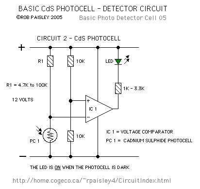
In this circuit, when the light falling on the phototransistor (Q1) is blocked, its conductance will decrease and the voltage across Q1 will rise. When the voltage rises above 1/2 of the supply voltage the output of the comparator will turn ON and the LED will be lit.The only critical part of this circuit is the value of resistor R1 which in most cases can be 470K ohms but may have to be increase if the room is dark or decreased if the room is well lit.
Increasing the value of R1 will cause the sensitivity of the sensor to decrease. This may be necessary when the light falling on the cell is not very strong or shadows can affect the phototransistor.
There are a number of phototransistors sizes and case styles. The smaller cases will be easier to hide but connecting wires may be more difficult. (View)
View full Circuit Diagram | Comments | Reading(1581)
Low Tech Meters For DCC Systems
Published:2013/6/21 2:40:00 Author:muriel | Keyword: Low Tech Meters, DCC Systems
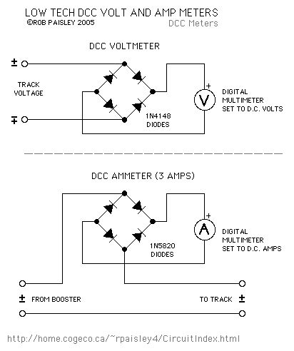
These are inexpensive low tech methods for measuring voltages and currents in DCC track systems. They are not as accurate as a high frequency AC volt and amp meters but if you only need an approximate indication these circuits will do the job.
The 1N5819 and 1N5820 diodes used here are Schottky types. This type of diode have a lower forward voltage drop (0.3V vs. 0.7V) than typical silicon diodes such as the 1N4000 series and can operate at efficiently at high frequencies.
(View)
View full Circuit Diagram | Comments | Reading(1324)
Battery testing Circuit
Published:2013/6/18 20:58:00 Author:muriel | Keyword: Battery testing Circuit
View full Circuit Diagram | Comments | Reading(1675)
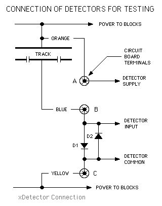
Connection Of Detectors
Published:2013/6/18 3:54:00 Author:muriel | Keyword: Connection, Detectors
View full Circuit Diagram | Comments | Reading(870)
LM 555 Photo-Detector With Delayed Release
Published:2013/6/18 3:47:00 Author:muriel | Keyword: LM 555, Photo-Detector , Delayed Release

View full Circuit Diagram | Comments | Reading(1196)
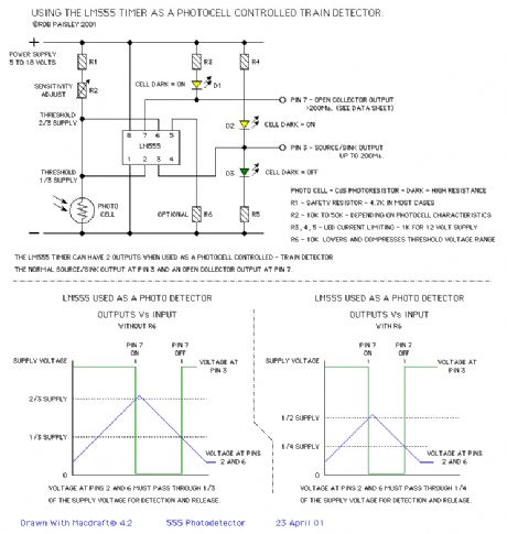
555 Photo-Detector Design Guide Sheet
Published:2013/6/18 3:47:00 Author:muriel | Keyword: 555 Photo-Detector, Design Guide Sheet
View full Circuit Diagram | Comments | Reading(1073)
Light Activated Detector Circuit
Published:2013/6/18 3:46:00 Author:muriel | Keyword: Light Activated Detector Circuit
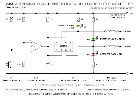
This page shows three circuits for using the 555 timer IC as a photocell controlled train detector.
The circuit is shown driving light emitting diodes but any load of less than 200 milliamps could be used.
Shown on the schematic is a secondary output that uses the open collector at the DISCHARGE terminal (Pin 7) of the timer. This output can sink a fairly large current and would be ideal for driving relays. (View)
View full Circuit Diagram | Comments | Reading(1290)
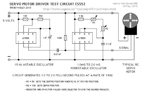
Servo Motor Test Circuit (LM555)
Published:2013/6/13 1:40:00 Author:muriel | Keyword: Servo Motor, Test Circuit , LM555
View full Circuit Diagram | Comments | Reading(2444)
AC Only - Block Occupancy Detector
Published:2013/6/13 1:29:00 Author:muriel | Keyword: AC Only, Block Occupancy Detector

View full Circuit Diagram | Comments | Reading(1217)
Day and Night Detector Circuit
Published:2013/6/6 20:53:00 Author:muriel | Keyword: Day and Night, Detector Circuit
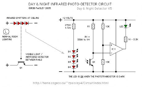
The detector for this circuit uses a voltage comparator the same as those on the Visible and Infrared Light Detectors page at this site.
The major change is the mounting of infrared emitters mounted at ceiling height above the detectors phototransistor. (View)
View full Circuit Diagram | Comments | Reading(1192)
4 - Infrared Detectors Schematic
Published:2013/6/6 20:48:00 Author:muriel | Keyword: 4 , Infrared Detectors Schematic
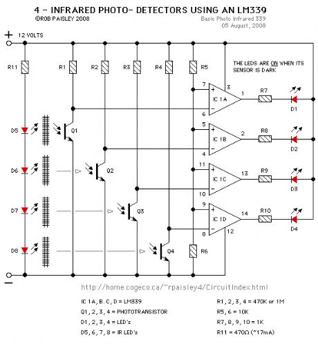
The schematic shows how the LM339 can be used to build a multiple detector unit.
In order to reduce on the total current needed for the circuit the infrared LED's can be wired in series and the value of the series resistor adjusted to supply the needed current. In this way the LED's use the same 17 milliamps instead of needing 17 milliamps each.
The parts values shown on the schematic are guidelines that should work in most situations but may have to be adjusted for your particular needs.
(View)
View full Circuit Diagram | Comments | Reading(1309)
Long Range - Across The Track Infrared Detectors
Published:2013/6/6 20:47:00 Author:muriel | Keyword: Long Range, Track Infrared Detectors

The method shown below has been tested with sensor gaps as wide as 12 inches but a distance of 8 inches or less is more practical.
There is also a method that can be used for longer range across track detection that could be used for yard throats. A detector circuit of this type is in use at the London Model Railroad Group's club layout and spans seven O Scale tracks using one infrared LED and a lensed phototransistor.
(View)
View full Circuit Diagram | Comments | Reading(1023)
Basic Infrared Detector Schematic
Published:2013/6/6 20:47:00 Author:muriel | Keyword: Basic Infrared, Detector Schematic

This page presents information on infrared - Above The Track and Across The Track train position detection circuits. The circuits are designed around the LM339 quad comparator chip and can use a wide assortment of matched infrared - emitter / detector pairs.
The circuit bellow is the basic voltage comparator based detector circuit using the LM339 Quad or LM393 Dual comparator ICs.
The LED will turn on when the infrared beam is broken. The value of the resistor R1 determines the sensitivity of the phototransistor Q1. In most cases a value of 1 Meg or 470K ohm with good results but every situation is different and some experimentation might be needed.
Circuit Operation - When a train breaks the infrared beam the phototransistor will conduct less current. The voltage at the MINUS input of the comparator will rise above the reference voltage at the PLUS as determined by R3 and R4. The output of the comparator to turn ON and the LED will be lit. (View)
View full Circuit Diagram | Comments | Reading(1445)
| Pages:3/101 1234567891011121314151617181920Under 20 |
Circuit Categories
power supply circuit
Amplifier Circuit
Basic Circuit
LED and Light Circuit
Sensor Circuit
Signal Processing
Electrical Equipment Circuit
Control Circuit
Remote Control Circuit
A/D-D/A Converter Circuit
Audio Circuit
Measuring and Test Circuit
Communication Circuit
Computer-Related Circuit
555 Circuit
Automotive Circuit
Repairing Circuit