
Remote Control Circuit
Index 17
MN|4821JTD(TV) remote control microprocessor
Published:2011/7/8 9:25:00 Author:Lena | Keyword: TV set, remote control, microprocessor
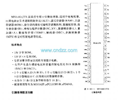
MN14821JTB is a remote control 4-bit microprocessor, usually used in TV set etc. The internal circuit consists of Arithmetic Logical Unit (ALU),Random-access memory(RAM),Read-only memory(ROM),instruction encoder and Programmable Logic Array, data flip-latch, instruction register, stack and program counter(PC,XY),data flip-latch(L),accumulator(A),data register(TEMP),decoder(DEC),multiplexer(MPX) and timing control circuit.
Specifications:
12k byte ROM
128 *4 bit RAM
Special interface circuit is used to display characters in the screen
D/A converter (DAC1 and DAC2) used for produce selective tuned voltage and volume control voltage
two 4-bit input ports(A and B),two 4-bit output ports(D and E ),one 9-bit dispersed output port(C),and relevant data flip-latch.77 instructions(16 branch conditional transfer commands)
assorted used types are M50142P,μPC1373H and μPD4049
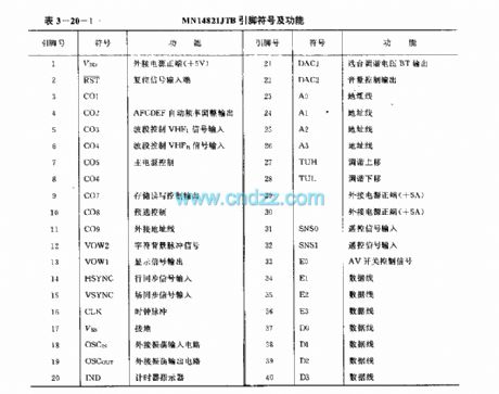
pinouts and functions
(View)
View full Circuit Diagram | Comments | Reading(1896)
Fan remote control speed regulation circuit TX315B1
Published:2011/7/8 5:57:00 Author:TaoXi | Keyword: Fan speed, remote control, speed regulation
Fan remote control speed regulation circuit TX315B1
(View)
View full Circuit Diagram | Comments | Reading(850)
Remote control discoloration droplight TDC1808/TDC1809
Published:2011/6/14 2:52:00 Author:TaoXi | Keyword: Remote control, discoloration, droplight
Each time when you press the button, the mute signal output terminal MUTE will output the low-level voltage to make the external light emitting diode to flash one time as the output instruction. The coded signal is sent out by the MK5087's TONE port and this signal gets to the launch component TDC1808 through resistance R2; in the receiving circuit, the receiving & demodulation output signal of the TDC1809 receiving component is decoded by the YN9102 DTMF decoder, the binary code that is sent out by the D1~D4 ports (corresponding to the launch instruction encoding phase) can be controlled by the SCR, then SCR controls the 4 kinds of color of colored lights.
(View)
View full Circuit Diagram | Comments | Reading(905)
The Multichannel wireless remote control circuits F36-F and F36-J
Published:2011/6/14 2:50:00 Author:TaoXi | Keyword: Multichannel, wireless remote control
This circuit uses the multichannel wireless remote control circuit which is composed of the F36-F and F36-J. In the transmission circuit, we use the DTMF coding & decoding circuit to change the launch button input signal into the 4-bit binary code and then input this signal to the F36-F to send out. In the receiving circuit, the F36-J receives the remote control signal and changes this signal into the 4-bit binary code, then changes this 4-bit binary code into the channel control signal through a four-sixteen line decoder to control the corresponding circuit.
Theremote controltransmission circuit:
The receiver decoding circuit:
(View)
View full Circuit Diagram | Comments | Reading(837)
The DTMF coding sixteen-channel remote control circuit
Published:2011/6/14 2:50:00 Author:TaoXi | Keyword: DTMF, coding, sixteen-channel, remote control
Transmitter circuit:
Receiving circuit:
(View)
View full Circuit Diagram | Comments | Reading(921)
The DTMF seven-channel remote controllers MK5087 and TDA7010
Published:2011/6/14 2:50:00 Author:TaoXi | Keyword: DTMF, seven-channel, remote controller
The transmitter circuit which is composed of the DTMF encoder MK5087 and the coding keyboard:
The receiving circuit:
(View)
View full Circuit Diagram | Comments | Reading(1060)
The TV remote controller 21
Published:2011/6/14 2:51:00 Author:TaoXi | Keyword: TV, remote controller
TV remote controller 21
(View)
View full Circuit Diagram | Comments | Reading(770)
Radio control explosive device which is composed of the S%26P27A/S%26P27B
Published:2011/6/14 3:00:00 Author:TaoXi | Keyword: Radio control, explosive device
In the exploitation of mines and the blasting of rock material, the radio control explosive method is more flexibility, reliability and economy than the method of wire control. The radio control explosive device which is composed of the S%26P27A/S%26P27B is as shown in the figure.
(a) is the eadio remote control transmitter circuit, (b) is the radio reception and demodulation circuit.
(View)
View full Circuit Diagram | Comments | Reading(851)
The long distance remote control switch which is composed of the S%26P27A/S%26P278
Published:2011/6/14 3:00:00 Author:TaoXi | Keyword: remote control, long distance
(a) is the remote control transmitter circuit, this circuit uses the digital coding circuit VD5026 as the address encoder, and it uses the three-state encoding mode and can compose multiple extensions (the transmitter is used as the extension or the receiver is used as the extension). (b) is the receiving circuit, it is composed of the receiver module and the decoding circuit VD5027 and the relay K.
(View)
View full Circuit Diagram | Comments | Reading(1016)
The Pulse dialing nine-channel infrared remote control circuits of the LR40992 and μPC1373
Published:2011/7/8 6:00:00 Author:TaoXi | Keyword: Pulse dialing, nine-channel, infrared remote control
The transmitter circuit:
The receiver circuit:
(View)
View full Circuit Diagram | Comments | Reading(884)
Pulse dialing ten-channel infrared remote control circuits of the UM9151 and μPC1373
Published:2011/7/8 6:00:00 Author:TaoXi | Keyword: Pulse dialing, ten-channel, infrared remote control
The transmitter circuit:
The receiver decoding and control circuit:
(View)
View full Circuit Diagram | Comments | Reading(888)
Code hopping radio control circuit TR1300/1315
Published:2011/7/8 5:58:00 Author:TaoXi | Keyword: Code hopping, radio control
The radio transmission circuit:
The remote control receiver demodulation and decoding output circuit:
(View)
View full Circuit Diagram | Comments | Reading(916)
Transceiver module composed of the wireless remote control fan governor RCM1A/RCM1B
Published:2011/7/8 5:59:00 Author:TaoXi | Keyword: Transceiver module, wireless remote control, fan governor
This governor has three gears of wind speed: strong, middle and weak, you can control it by the wireless remote control method or touch the switch, and this governor can be used to transform the touch mode ceiling fans and electric fans. You can connect it to the electric fan motor after the installation is complete, for the motor with the speed shaft head, you can connect it according to the above figure. For the motor with the speed reactor, you can connect it according to the figure.
(View)
View full Circuit Diagram | Comments | Reading(993)
Bean Sprouting Machine Constant Temperature Controller
Published:2011/7/10 7:27:00 Author:Sue | Keyword: Bean Sprouting Machine, Constant Temperature, Controller
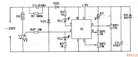
When the power is on, the temperature of the bean sprouting machine is lower than RP3's given control temperature. RT's resistance value is large and IC's pin 2's and pin 6's voltages are both lower than pin 5's voltage. Pin 3 outputs high level and VT is connected. Heating wire EH begins to be heated. As the temperature is becoming higher and higher, RT's resistance value is becoming smaller and smaller. When the temperature reaches the given temperature, IC's pin 2's voltage is higher thanhalf of pin 5's voltage. When its pin 6's voltage is higher than or equal to pin 5's voltage, IC's inner circuit will be reversed. Its pin 3 outputs low level and VT is disconnected and EL stops being heated. As the temperature is becoming lower and lower, RT's resistance value is becoming higherand higher which will make IC's pin 2 and pin 6 have lower voltages. When IC's pin 6's voltage is lower than pin 5's voltage, its pin 2's voltage is lower than or equal to half of pin 5's voltage, IC's pin 3 will have high level again which will make VT connected. EH begins to be heated again. (View)
View full Circuit Diagram | Comments | Reading(1223)
The output protection circuit of digital integrated circuit
Published:2011/7/7 6:48:00 Author:Sophia | Keyword: Digital integrated circuit, Output protection circuit
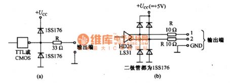
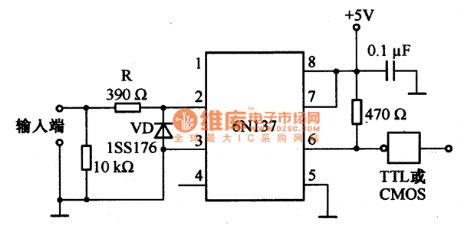
The output of digital integrated circuits must also be protected. Figure a, bare the output protection circuit. Figure a is common protection circuit, Figure (b) is the protection circuit of ELA-422-A. It is the same as the input protection circuit, and resistance R is used to limit the current flowing through output, the diode is used to limit the external input signal level and limit the signal in the range of (0.6V) ~ (Ucc +0.6 V). The resistivity of resistance R is slightly lower than the resistivity of input protective resistance, so that the impact of pressure drop on R can be reduced. (View)
View full Circuit Diagram | Comments | Reading(1589)
The protection circuit adopting photo-coupler
Published:2011/7/7 7:04:00 Author:Sophia | Keyword: protection circuit, photo-coupler
(View)
View full Circuit Diagram | Comments | Reading(965)
The battery, starter and engine circuit of Passat 2.81V
Published:2011/7/7 21:17:00 Author:Seven | Keyword: engine circuit, starter
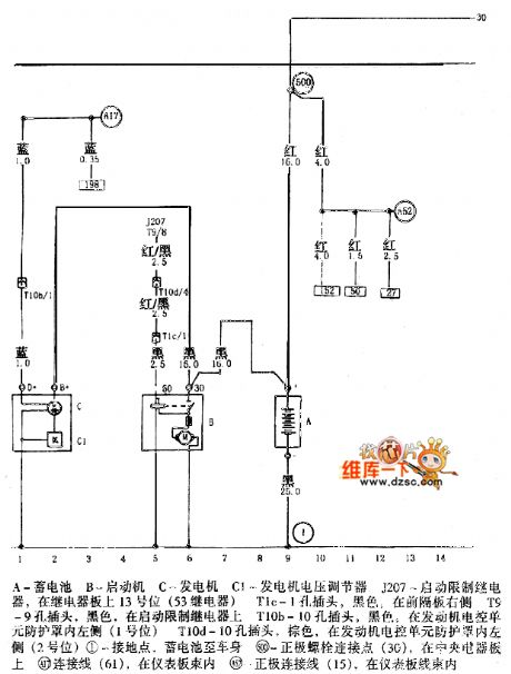
The battery, starter and engine circuit of Passat 2.81V is shown as above.A-battery B-starter C-generator C1-voltage regulator of the generator J207- the starting limit relay, on the 13 spot of the board(53 relay) T1c-one-hole plug, black, on the right side of the angle divider T9-9-hole plug, black, on the starting limit relay T10b-10-hole plug, black, on the left side of the shield of the generator control unit(No.1 spot)T10d-10 -hole plug, black, on the left side of the shield of the generator control unit(No.2 spot)①-ground connection spot, from the battery to the car body (View)
View full Circuit Diagram | Comments | Reading(1159)
The dual-way control SCR liquid level control circuit
Published:2011/7/7 20:24:00 Author:Seven | Keyword: dual-way control, liquid level
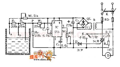
See as the figure, the controller consists of liquid level, trigger controller and step-down rectifier circuit, etc. The water level detecting poles of a, b and c compose the bias circuit as the water level detector with W1, R1, R2 and R3. When the water level is below b , Vp-b≈R3×VDD/(Rw1+R1+R2+R3)<1/3VDD, 555 is offset, SCR is triggered and conducting, the motor is running and drawing water. When the level is over a , Vp-a≈R3×VDD/(Rw1十R3)>2/3VDD, so 555 is reset, 3-pin is in a low LEV, SCR is blocked and the motor stops. (View)
View full Circuit Diagram | Comments | Reading(2923)
Tank-type water level control circuit
Published:2011/7/6 9:09:00 Author:John | Keyword: water level
View full Circuit Diagram | Comments | Reading(1322)
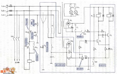
Voltage type leakage protection circuit
Published:2011/7/4 0:44:00 Author:John | Keyword: leakage protection
View full Circuit Diagram | Comments | Reading(883)
| Pages:17/34 1234567891011121314151617181920Under 20 |
Circuit Categories
power supply circuit
Amplifier Circuit
Basic Circuit
LED and Light Circuit
Sensor Circuit
Signal Processing
Electrical Equipment Circuit
Control Circuit
Remote Control Circuit
A/D-D/A Converter Circuit
Audio Circuit
Measuring and Test Circuit
Communication Circuit
Computer-Related Circuit
555 Circuit
Automotive Circuit
Repairing Circuit