
Remote Control Circuit
Index 9
LB1475 (video tape recorder) two-wire wired remote control circuit
Published:2011/7/27 22:15:00 Author:TaoXi | Keyword: video tape recorder, two-wire, wired, remote control circuit
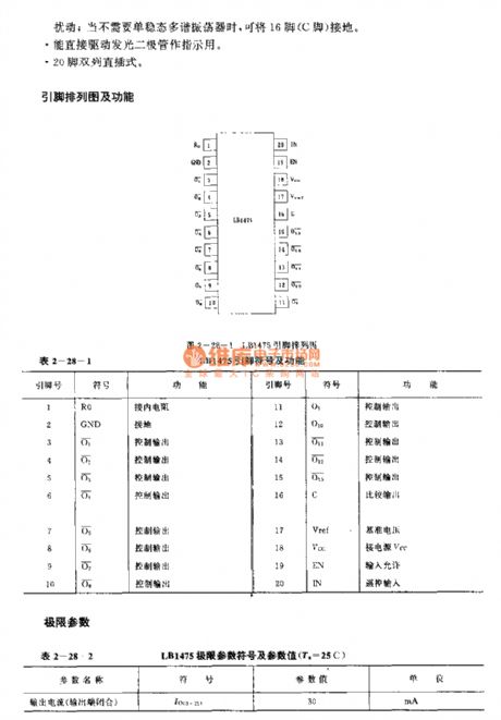
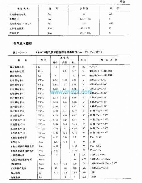
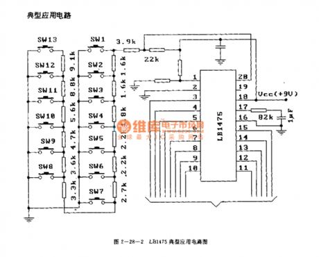
FeaturesYou can complete 13 kinds of remote control functions by using only two control lines between the controller and the remote control equipment.
It has the monostable multivibrator, the oscillation frequency is controlled by the external components, and this monostable multivibrator can be used to inhibit the disturbance which is produced by the switch conversion; when you do not want to use the monostable multivibrator, you can connect the pin-16 with the ground.
It can drive the light-emitting diode directly.
20-pin dual-row DIP package.
(View)
View full Circuit Diagram | Comments | Reading(2156)
LM909 (electronic toys) radio remote control receivier decoding circuit
Published:2011/7/28 0:53:00 Author:TaoXi | Keyword: electronic toys, radio, remote control, receivier, decoding circuit
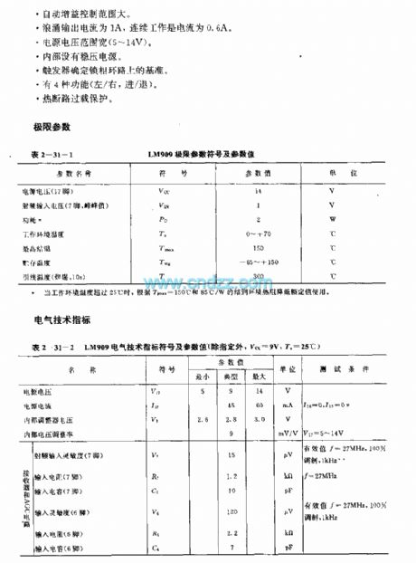
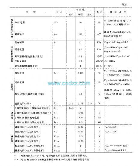
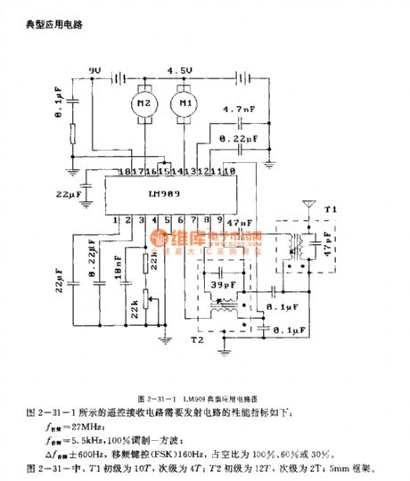
The LM909 is designed as the radio remote control receivier decoding circuit that can be used in the electronic toys application. The circuit is composed of the radio frequency amplifier, the automatic gain control (AGC) circuit, the wave detector, the phase locked loop, the level detection circuit and the push-pull output circuit.
Features
The decoding frequency is 40MHz.The RF sensitivity is high.It has the audio PLL demodulator.The automatic gain control range is wide.The surge output current is 1A, the continuous operating current is 0.6A.The power supply voltage range is wide (5-14V).It has the voltage-stabilized power supply.
(View)
View full Circuit Diagram | Comments | Reading(2029)
LM1872 (electronic toys and model cars) radio, infrared ray remote control receiving decoder circuit
Published:2011/7/28 1:08:00 Author:TaoXi | Keyword: electronic toys, model cars, radio, infrared ray, remote control, receiving, decoder circuit
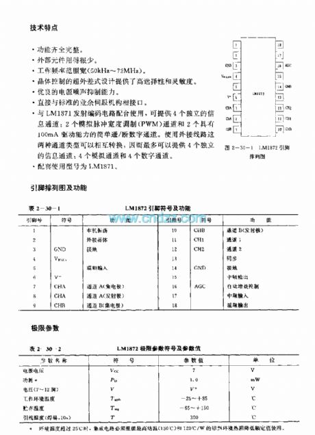

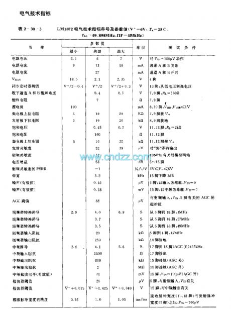
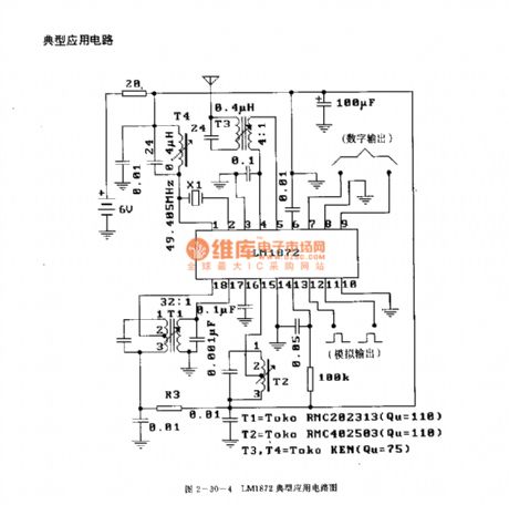
The LM1872 is designed as the radio or infrared ray remote control receiving decoder circuit that can be used in the electronic toys and model cars. The internal circuit is composed of the logic unit circuit, the local oscillator, the voltage regulator, the intermediate frequency circuit, the AGC circuit, the wave detector and the synchronous circuit.
Features
The function is complete.The external components is few.The operating frequency is wide (50kHz-72MHz).The specialized superheterodyne type design supplies the high selectivity and sensitivity.It has good power supply noise rejection capability.It connects with the standard spare servo mechanism directly.The matching model is LM1871.
(View)
View full Circuit Diagram | Comments | Reading(3389)
M50116P/AP/BP/CP (video recorder, TV and audio equipment) 60-function infrared remote control receiving circuit
Published:2011/8/1 4:57:00 Author:TaoXi | Keyword: video recorder, TV, audio equipment, 60-function, infrared, remote control, receiving circuit
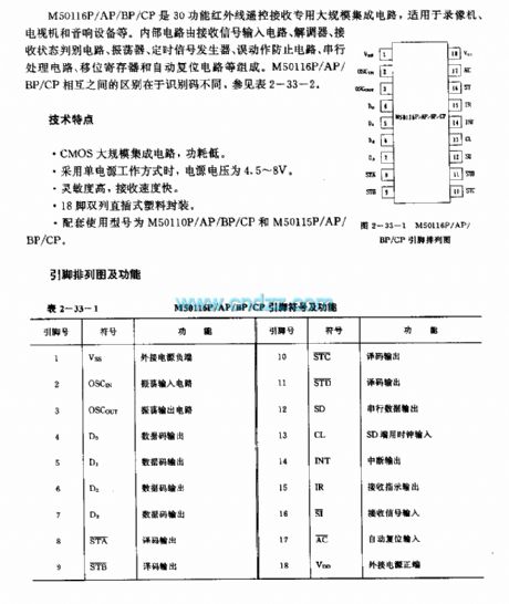
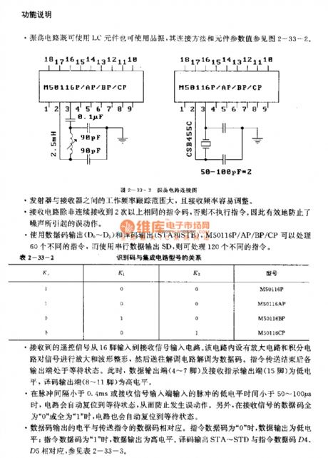
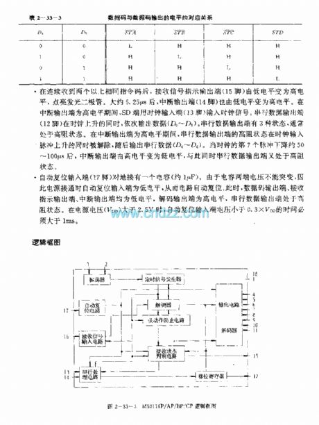
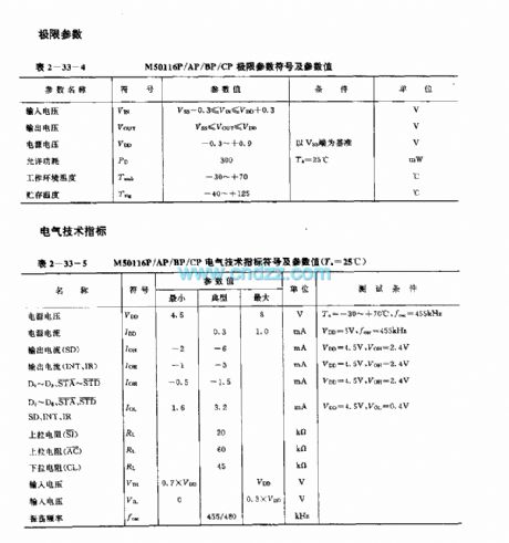
The M50116P/AP/BP/CP is designed as the 30-function infrared remote control receiving circuit that can be used in the video recorder, TV and audio equipment applications. The internal circuit is composed of the receiving signal input circuit, the demodulator, the receiving state discriminant circuit, the oscillator, the timing signal generator, the malfunction prevention circuit, the serial processing circuit, the shifting register and the automatic reset circuit. The differences between the M50116P, M50116AP, M50116BP, M50116CP are the identification numbers.
Features
CMOS large scale integrated circuit, the power consumption is low.When it uses the single power operating mode, the power voltage is 4.5-8V.The high sensitivity, fast receiving speed.18-pin dual-row DIP plastic package.The matching models are M50116P, M50116AP, M50116BP, M50116CP and M50115P, M50115AP, M50115BP, M50115CP.
(View)
View full Circuit Diagram | Comments | Reading(1434)
M50117F/AP/BP/CP (VCR, TV and audio equipment) 120-function infrared remote control receiver circuit
Published:2011/8/1 5:01:00 Author:TaoXi | Keyword: VCR, TV, audio equipment, 120-function, infrared, remote control, receiver circuit
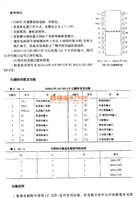
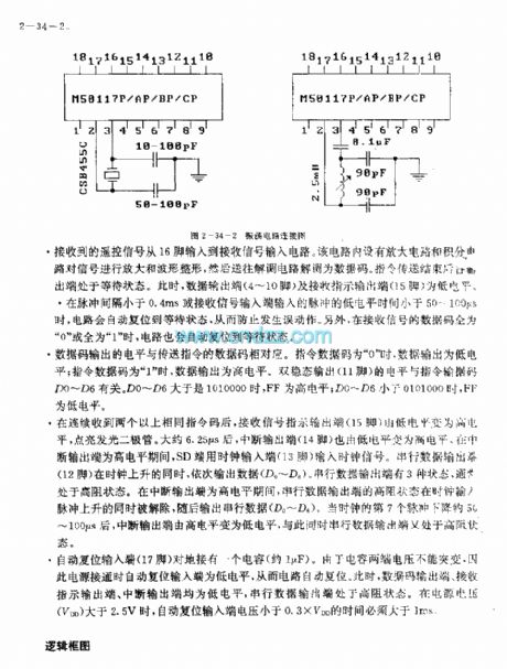
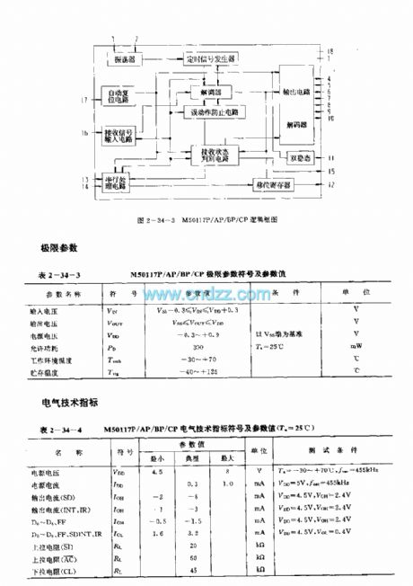
The M50117F/AP/BP/CP is designed as the 120-function infrared remote control receiving circuit that can be used in the video recorder, TV and audio equipment applications. The internal circuit is composed of the receiving signal input circuit, the demodulator, the receiving state discriminant circuit, the oscillator, the timing signal generator, the malfunction prevention circuit, the serial processing circuit, the shifting register and the automatic reset circuit. The differences between the M50117P, M50117AP, M50117BP, M50117CP are the identification numbers.
Features
CMOS large scale integrated circuit, the power consumption is low.When it uses the single power operating mode, the power voltage is 4.5-8V.The high sensitivity, fast receiving speed.18-pin dual-row DIP plastic package.The matching models are M50110P, M50110AP, M50110BP, M50110CP and M50115P, M50115AP, M50115BP, M50115CP.
(View)
View full Circuit Diagram | Comments | Reading(1327)
M50111P/AP/BP/CF (video recorder, television and audio equipment) 30-function infrared remote control receiver circuit
Published:2011/8/1 5:04:00 Author:TaoXi | Keyword: video recorder, television, audio equipment, 30-function, infrared, remote control, receiver circuit
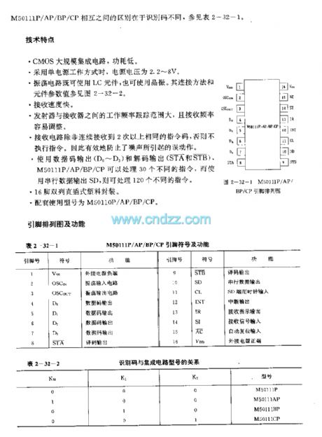
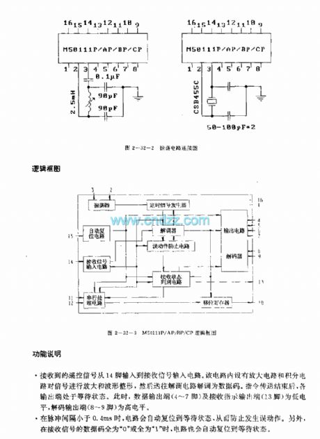
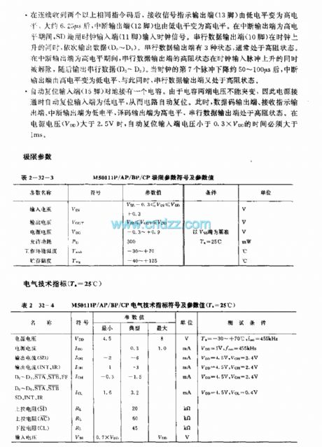
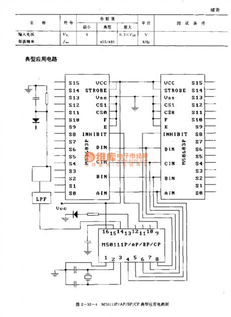
The M50111P/AP/BP/CF is designed as the 30-function infrared remote control receiving circuit that can be used in the video recorder, TV and audio equipment applications. The internal circuit is composed of the receiving signal input circuit, the demodulator, the receiving state discriminant circuit, the oscillator, the timing signal generator, the malfunction prevention circuit, the serial processing circuit, the shifting register and the automatic reset circuit. The differences between the M50117P, M50117AP, M50117BP, M50117CP are the identification numbers.
Features
CMOS large scale integrated circuit, the power consumption is low.When it uses the single power operating mode, the power voltage is 2.2-8V.The high sensitivity, fast receiving speed.16-pin dual-row DIP plastic package.The matching models are M50110P, M50110AP, M50110BP, M50110CP.
(View)
View full Circuit Diagram | Comments | Reading(1716)
SL517 (electronic toy) audio, RF or infrared decoder circuit
Published:2011/8/1 20:29:00 Author:TaoXi | Keyword: electronic toy, audio, RF, infrared decoder
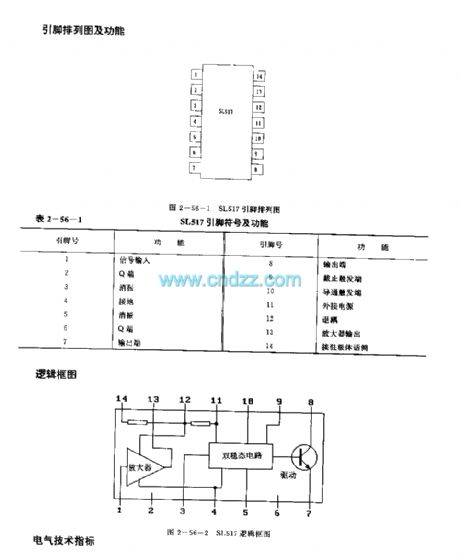
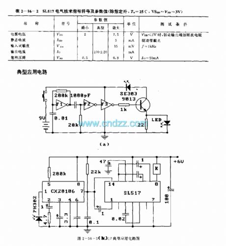
The SL517 is designed as the audio, RF or infrared decoder circuit that can be used in the electronic toy application. The internal circuit is composed of the analog amplifier, the frequency divider, the bistable circuit and the driver.
Features
It uses the CMOS technology.The power voltage range is wide, the value is 2-7.5V.The quiescent current is small (</=5mA).The external components are little.The high sensitivity (</=15mV).The strong anti-interference ability.Bistable output, the driving current is large (100+/-20mA).Simple assembly debugging, stable and reliable performance.
(View)
View full Circuit Diagram | Comments | Reading(2394)
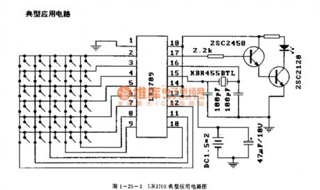
LR3709 (video tape recorder) infrared remote control launch circuit
Published:2011/8/1 20:59:00 Author:TaoXi | Keyword: video tape recorder, infrared, remote control, launch circuit
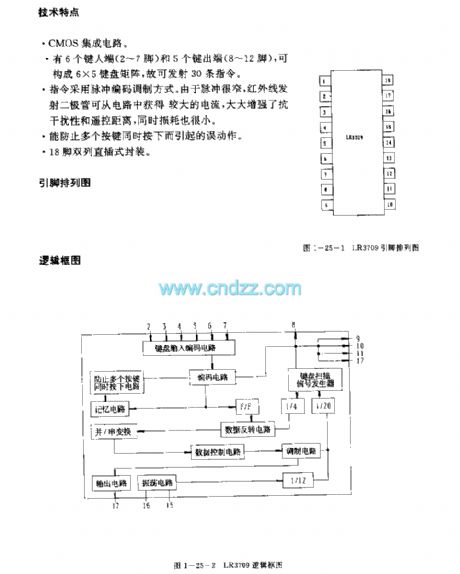
Features
The CMOS IC.It has six input ports (pin-2 to pin-7) and five output ports (pin-8 to pin-12), and they can form the 6X5 keyboard matrix, so this device can launch 30 instructions.The instructions use the pulse coding modulation mode. Because the pulse is narrow, the infrared emission diode can get the large current from the circuit to enhance the anti-jamming performance and the remote distance, also the power consumption is small.It can prevent the error action.18-pin dual-row DIP package.
(View)
View full Circuit Diagram | Comments | Reading(1307)
M50110P/AP/BP/CP (video recorder, TV and audio equipment) 30-function infrared remote control launch circuit
Published:2011/8/1 8:58:00 Author:TaoXi | Keyword: video recorder, TV, audio equipment, 30-function, infrared, remote control, launch circuit
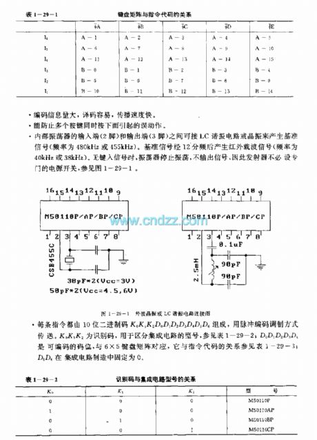
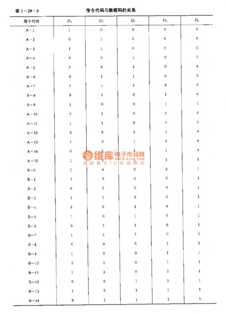
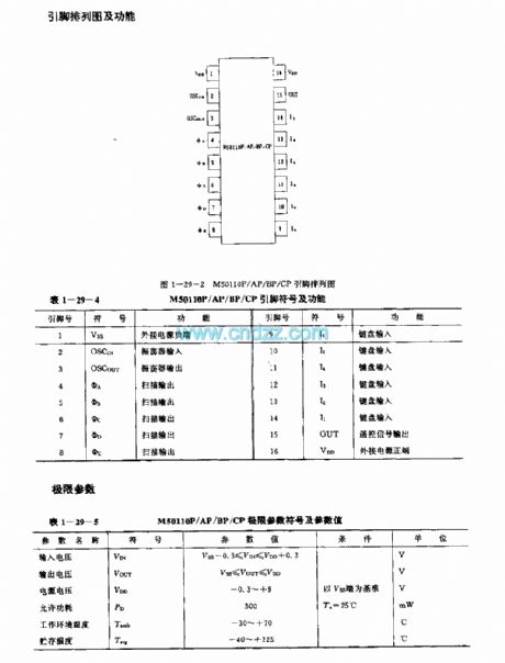
The M50110P/AP/BP/CP is designed as the 30-function infrared remote control launch circuit that can be used in the video recorder, TV and audio equipment applications. The internal circuit is composed of the keyboard input encoder, the instruction decoder, the oscillator, the timing signal generator, the scanning signal generator, the Coding modulator and the output buffer. The difference between the M50110P, M50110AP, M50110BP, M50110CP is the identification number.
Features
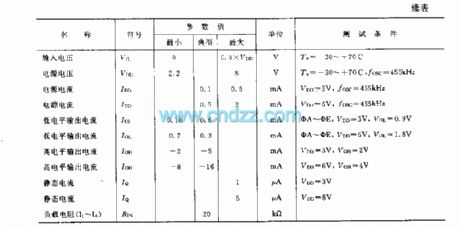
It uses the single power operating mode, the power voltage is 2.2-8V.The oscillator will stop operating when the keyboard buttons are not pressed to reduce the power consumption.The duty ratio is small to reduce the power consumption of the diode.The external components are few, the SNR is high, the anti-interference ability is strong.It has six input ports and five output ports to form the 6X5 keyboard matrix.The matching models are M5011P/AP/BP/CP, M50116P/AP/BP/CP and M50117P/AP/BP/CP.
(View)
View full Circuit Diagram | Comments | Reading(1189)
LR3710AM (video tape recorder) infrared remote control launch circuit
Published:2011/8/1 21:06:00 Author:TaoXi | Keyword: video tape recorder, infrared, remote control, launch circuit
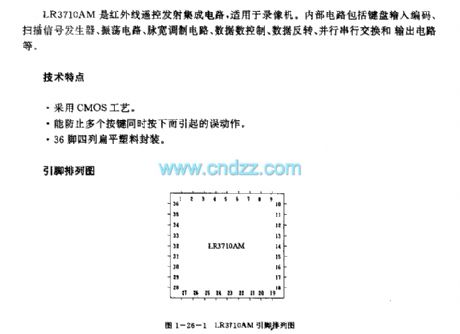
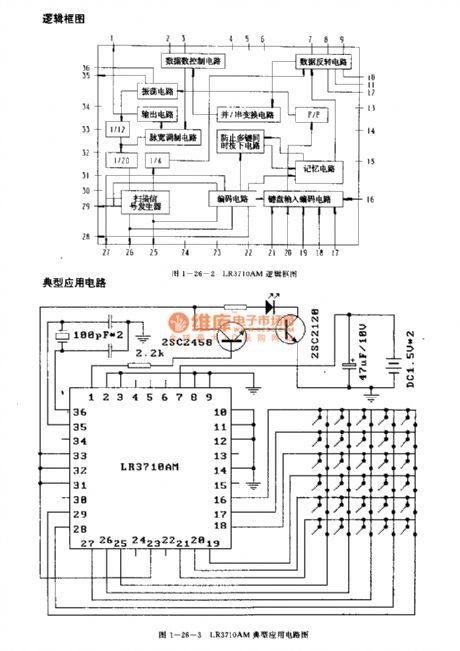
The LR3710AM is designed as the infrared remote control launch circuit that can be used in the video tape recorder application. The internal circuit is composed of the keyboard input coding circuit, the scanning signal generator, the oscillating circuit, the pulse width modulation circuit, the data control circuit, the data inversion circuit, the parallel serial switching circuit and the output circuit.
Features
It uses the CMOS technology.It can prevent the error action.It is in the 36-pin four-row flat plastic package.
(View)
View full Circuit Diagram | Comments | Reading(1256)
LR3714M (video tape recorder) infrared remote control launch circuit
Published:2011/8/1 21:13:00 Author:TaoXi | Keyword: video tape recorder, infrared, remote control, launch circuit
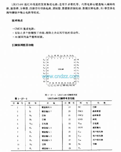
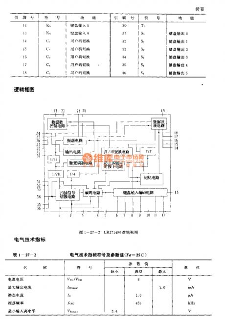
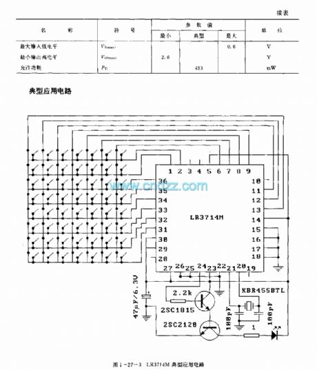
The LR3714M is designed as the infrared remote control launch circuit that can be used in the video tape recorder application. The internal circuit is composed of the keyboard input coding circuit, the scanning signal switching circuit, the oscillator, the modulator, the data control circuit, the data inversion circuit, the parallel serial switching circuit and the button pulse output circuit.
Features
It uses the CMOS technology.It can prevent the error action.It is in the 36-pin four-row flat plastic package.
(View)
View full Circuit Diagram | Comments | Reading(1248)
LR3715M (TV and video recorder) infrared remote control launch circuit
Published:2011/8/1 21:21:00 Author:TaoXi | Keyword: TV, video recorder, infrared, remote control, launch circuit
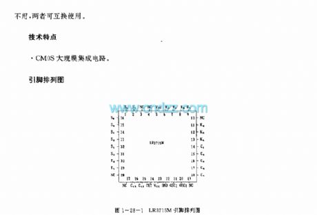
The LR3715M is designed as the infrared remote control launch circuit that can be used in the TV and video recorder applications. The LR3715M has the same technical features, pins arrangement, shape structure, absolute maximum ratings, electrical specifications, logic diagram and the typical applications with the LR3714M. The difference between the LR3715M and LR3714M is the pin-27. The LR3715M's pin-27 is empty, the LR3714M's pin-27 is the C14 port. They can be exchanged if we do not use the pin-27.
Features
The CMOS large scale integrated circuit.
(View)
View full Circuit Diagram | Comments | Reading(971)
LC2190 (air conditioner, electric fan, radio, TV and toy) infrared, ultrasonic and wireless remote control launch circuit
Published:2011/8/1 21:38:00 Author:TaoXi | Keyword: air conditioner, electric fan, radio, TV, toy, infrared, ultrasonic, wireless, remote control, launch circuit

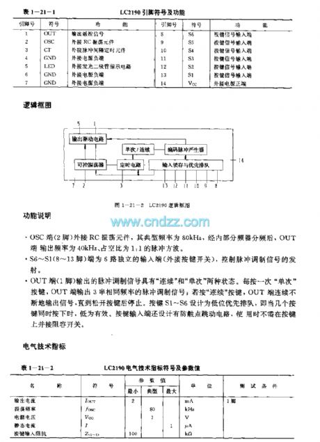
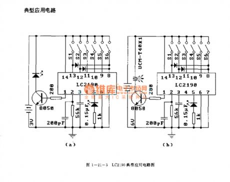
The LC2190 is designed as the infrared, ultrasonic and wireless remote control launch circuit that can be used in the air conditioner, electric fan, radio, TV and toy applications. The internal circuit is composed of the output driving circuit, the controllable oscillator, the timing cirucit, the coding pulse generator, the input latch circuit and the priority queuing circuit.etc.
Features
Low power consumption.Good anti-interference performance.Little external components.Easy to use.The external RC circuit forms the oscillating circuit. It does not need the crystal oscillator, so the cost of it is cheaper than other controllers.The matching model is LC2200.
(View)
View full Circuit Diagram | Comments | Reading(1860)
KS5410 (TV, video tape recorder and audio equipment) infrared remote control launch circuit
Published:2011/8/1 21:53:00 Author:TaoXi | Keyword: TV, video tape recorder, audio equipment, infrared, remote control, launch circuit
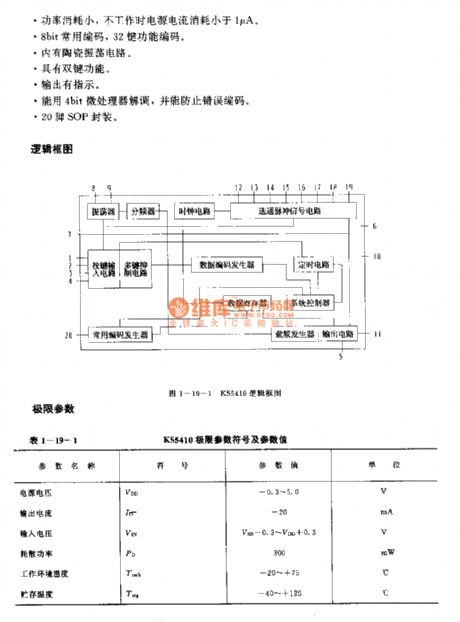
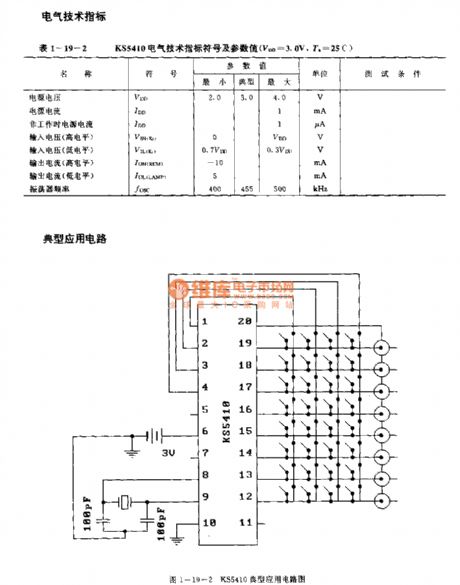
The KS5410 is designed as the infrared remote control launch circuit that can be used in the TV, video tape recorder and audio equipment applications. The internal circuit is composed of the oscillator, the frequency divider, the button input circuit, the multi-key suppression circuit, the common code generator, the data coding generator, the data register, the strobe pulse signal circuit, the clock circuit, the timing circuit, the system controller, the carrier frequency generator and the output current.
Features
The power voltage is low, the range is 2.0-4.0V.The transmission efficiency is high, the duty ratio is 1.8%.The power consumption is small, when it is not in the operating state, the power current consumption is smaller than 1uA.8-bit commonly used code, 32-button function code.It has the ceramic oscillating circuit.It has the double-button function.
(View)
View full Circuit Diagram | Comments | Reading(1542)
KS5803A/B (tape recorder, TV, video recorder and toy) infrared remote control launch circuit
Published:2011/8/1 22:01:00 Author:TaoXi | Keyword: tape recorder, TV, video recorder, toy, infrared, remote control, launch circuit
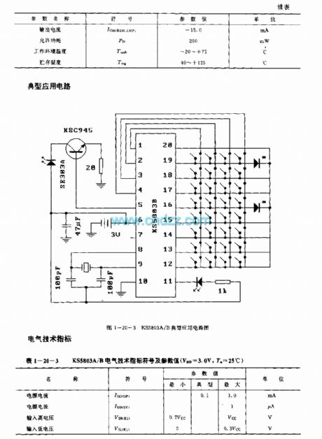
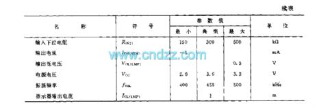
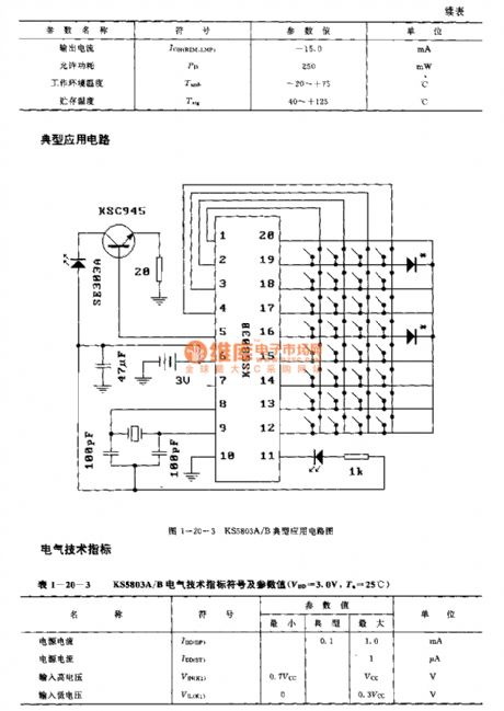
The KS5803A/B is designed as the infrared remote control launch circuit that can be used in the tape recorder, TV, video recorder and toy applications.
(View)
View full Circuit Diagram | Comments | Reading(1585)
LM1871 (electronic toys and model cars) wireless remote control launch coding circuit
Published:2011/8/2 3:43:00 Author:TaoXi | Keyword: electronic toys, model cars, wireless, remote control, launch, coding circuit

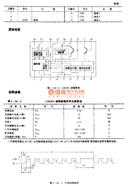
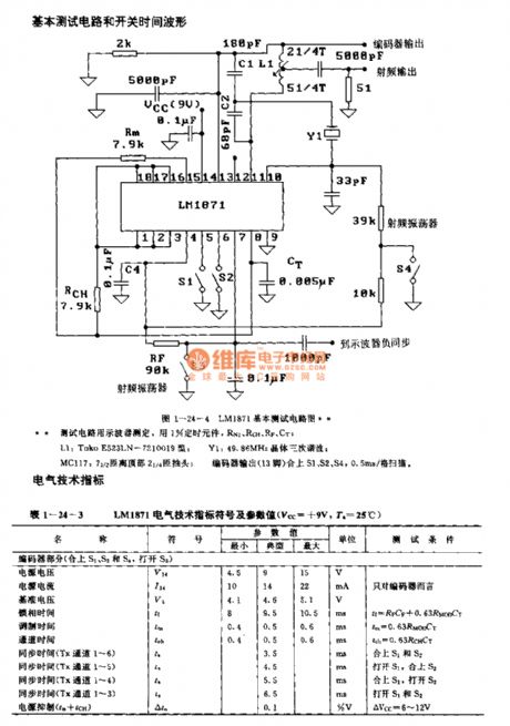
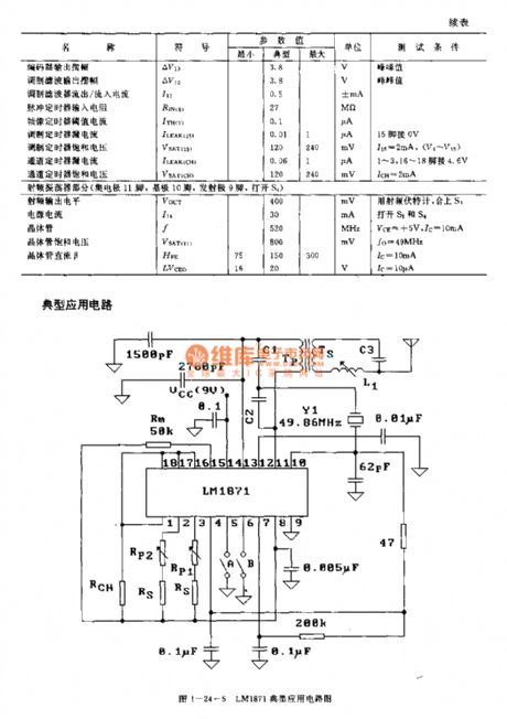
The LM1871 is designed as the wireless remote control launch coding circuit that can be used in the electronic toys and model cars. The internal circuit is composed of the channel addition logic circuit, the 4.6V voltage regulator, the encoder, the frame-picture timer and the pulse timer.
FeaturesThe IC has the radio frequency oscillator/transmitter and the 4.6V voltage regulator.The RF output power is adjustable.The six proportion channels use the same timing capacitor.The channel number is programmable. The external modulator controls the frequency band width.It can be used in the low power, non-speech signal and unauthorized communication devices with the carrier frequency of 27MHz or 49MHz and the 3m field strength of 10000uV/m.
(View)
View full Circuit Diagram | Comments | Reading(2180)
IJC7462M (TV) infrared remote control launch circuit
Published:2011/8/2 3:53:00 Author:TaoXi | Keyword: TV, infrared, remote control, launch circuit
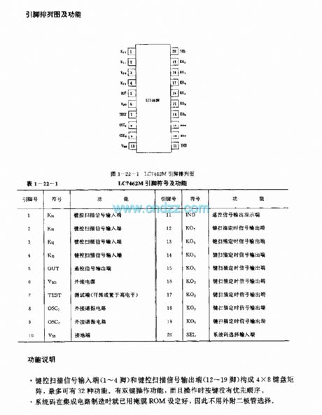
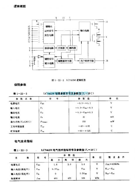
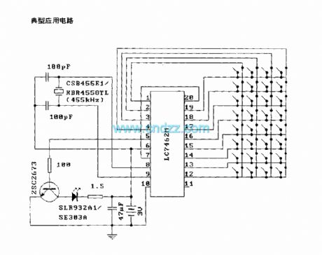
The IJC7462M is designed as the infrared remote control launch circuit that can be used in the TV application. The internal circuit is composed of the button output timing signal generator circuit, the button control signal input circuit, the button data register, the user code register, the oscillating circuit, the frequeny divider, the decoder.
Features
The CMOS large scale integrated circuit.In the standby state, the current consumption is lower than 10uA.It has the oscillating circuit, you can add the quartz resonator to form the clock oscillator.20-pin dual-row DIP plastic package.The matching model is CX20106A.
(View)
View full Circuit Diagram | Comments | Reading(3131)
KA2310 (toy) wireless remote control launch control regulation circuit
Published:2011/8/2 4:00:00 Author:TaoXi | Keyword: toy, wireless, remote control, launch, control, regulation circuit
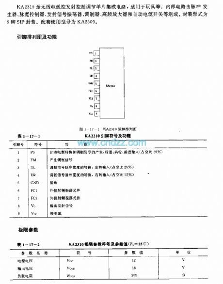
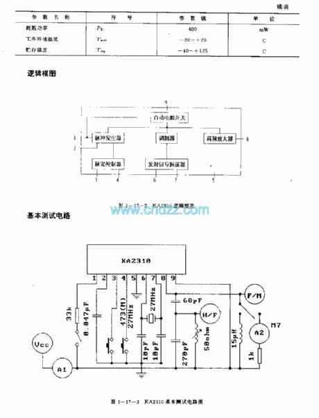
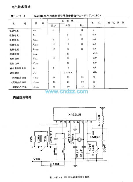
The KA2310 is designed as the wireless remote control launch control regulation circuit that can be used in the toy application. The internal circuit is composed of the pulse generator, the pulse width controller, the transmitting signal oscillator,the modulator, the high frequency amplifier and the automatic power switch. This device is in the 9-pin SIP package. The matching model is KA2309.
(View)
View full Circuit Diagram | Comments | Reading(2582)
KA2312 (toy) wireless remote control launch control regulation circuit
Published:2011/8/2 4:02:00 Author:TaoXi | Keyword: toy, wireless, remote control, launch, control, regulation circuit
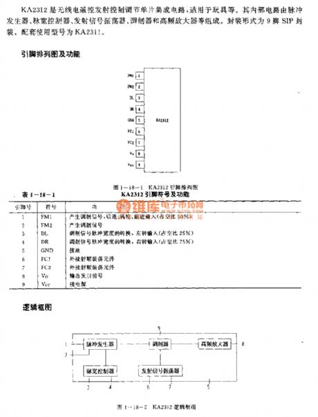

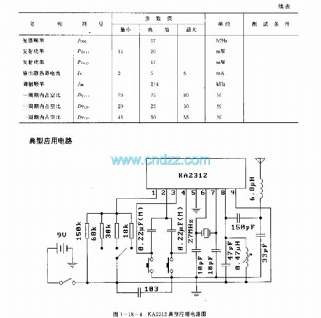
The KA2312 is designed as the wireless remote control launch control regulation circuit that can be used in the toy application. The internal circuit is composed of the pulse generator, the pulse width controller, the transmitting signal oscillator,the modulator, the high frequency amplifier and the automatic power switch. This device is in the 9-pin SIP package. The matching model is KA2311.
(View)
View full Circuit Diagram | Comments | Reading(1898)
GM3043 (TV and video tape recorder) infrared remote control launch circuit
Published:2011/8/1 9:01:00 Author:TaoXi | Keyword: TV, video tape recorder, infrared, remote control, launch circuit
The GM3043 has the same functions and pin arrangement with the uPD1943G, so they can exchange directly. The technical characteristics, absolute maximum ratings, main electrical specifications, logic diagram and typical application circuits of the GM3043 can reference the uPD1943G's. (View)
View full Circuit Diagram | Comments | Reading(841)
| Pages:9/34 1234567891011121314151617181920Under 20 |
Circuit Categories
power supply circuit
Amplifier Circuit
Basic Circuit
LED and Light Circuit
Sensor Circuit
Signal Processing
Electrical Equipment Circuit
Control Circuit
Remote Control Circuit
A/D-D/A Converter Circuit
Audio Circuit
Measuring and Test Circuit
Communication Circuit
Computer-Related Circuit
555 Circuit
Automotive Circuit
Repairing Circuit