
Remote Control Circuit
Index 12
Simple and reliable temperature measurement circuit
Published:2011/7/28 21:25:00 Author:John | Keyword: temperature measurement
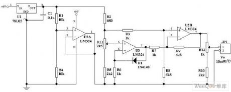
Any ordinary diode (eg IN4148), in principle, can be used as a fine electronic thermometer’s sensing element with certain precision. When the diode temperature is increased by 1 degree, its forward voltage drop will reduce 2mV.
As shown in the figure, a constant reference voltage is applied to the input end of op-amp A2. A diode and a resistor are applied to the inverting input of op-amp. Therefore, the current flows through the diode and also flows through the resistor. A constant pressure drop should be maintained on the resistor.
(View)
View full Circuit Diagram | Comments | Reading(2352)
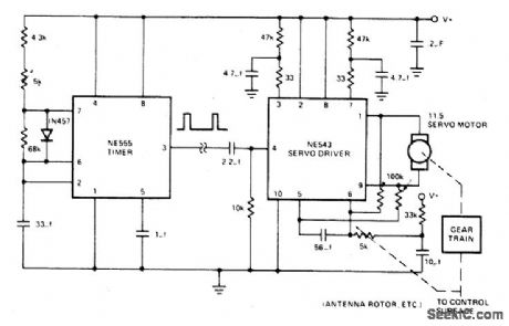
REMOTE_CONTROL_SERVO_SYSTEM
Published:2009/6/29 4:01:00 Author:May
View full Circuit Diagram | Comments | Reading(1110)
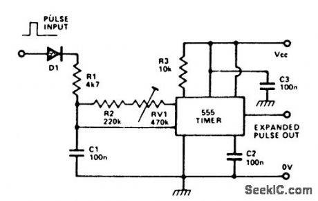
RADIO_CONTROL_MOTOR_SPEED_CONTROLLER
Published:2009/6/29 3:59:00 Author:May

View full Circuit Diagram | Comments | Reading(1040)
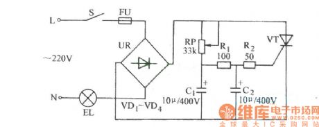
The thyristor light regulation circuit
Published:2011/7/21 3:19:00 Author:Seven | Keyword: thyristor, light regulation
View full Circuit Diagram | Comments | Reading(1042)
COMPACT_IR_RECEIVER
Published:2009/6/24 21:32:00 Author:Jessie
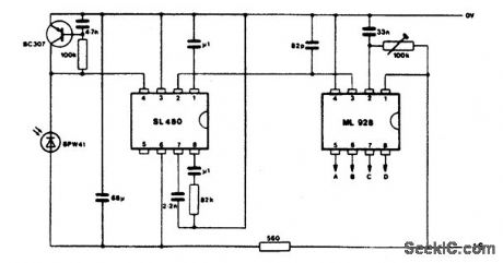
View full Circuit Diagram | Comments | Reading(1625)
IR_REMOTE_CONTROL_TRANSMITTER/RECEIVER
Published:2009/6/24 21:30:00 Author:Jessie
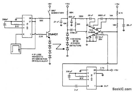
The circuit is designed to operate at 25 kHz. The data stream turns the 2N4401 hard on or off depending upon the coded state. This in turn switches the series infrared LEDs on and off. The receiver circuit consists of a three stage amplifier with photo diodes arrayed for maximum coverage of the reception area. The range of this set-up should be about 10 meters. (View)
View full Circuit Diagram | Comments | Reading(2718)
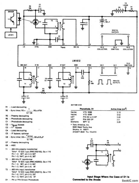
IR_TYPE_DATA_LINK
Published:2009/6/24 21:29:00 Author:Jessie
View full Circuit Diagram | Comments | Reading(1466)
ULTRASONIC_REMOTE_CONTROL_TESTER
Published:2009/6/24 21:27:00 Author:Jessie
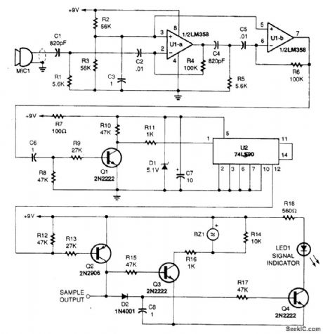
This circuit picks up the ultrasonic tone via MIC1, amplifies it, and divides it by 10 in IC U2, a 74LS90. The output of U2 drives an audio amplifier and a piezoelectric element is used as a speaker. (View)
View full Circuit Diagram | Comments | Reading(2068)
REGENERATIVE_RECEIVER_FOR_6_TO_17_MHz
Published:2009/6/24 4:49:00 Author:Jessie
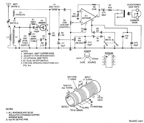
The headphones are 32-Ω stereo types.The common lead is left floating so that the two sides are in series,giving 64Ω. (View)
View full Circuit Diagram | Comments | Reading(3427)
TOROIDAL_CORE_TRF_SHORTWAVE_RECEIVER
Published:2009/6/24 4:45:00 Author:Jessie
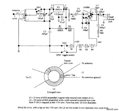
A ZN414 IC feeds an LM386 audio amplifier in this TRF circuit SW1is a band-switch,Coverageis up to 18 MHz. (View)
View full Circuit Diagram | Comments | Reading(4993)
RECEIVER_PREAMP
Published:2009/6/24 4:37:00 Author:Jessie
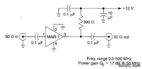
Suitable for HF and VHF receivers, this preamplifier can be mounted on the back of the receiver for a boost in gain. Useful gain is about 17 dB at 50 MHz (View)
View full Circuit Diagram | Comments | Reading(0)
SUPERHET_FRONT_END
Published:2009/6/24 4:36:00 Author:Jessie
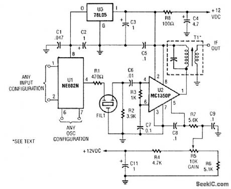
This superhet receiver front end is simple and uses an NE602 followed by an MC1350 IF amplifier. (View)
View full Circuit Diagram | Comments | Reading(6259)
BALANCED_LINE_RECEIVER
Published:2009/6/24 4:34:00 Author:Jessie
Unity-gain inverter U2 drives R4 (usually grounded at -Vout, equalizing currents in tinput legs, and provides a choice of balanced p-p output with a gain of R2/R1). (View)
View full Circuit Diagram | Comments | Reading(1940)
REMOTE_RE_CURRENT_READOUT
Published:2009/6/23 1:45:00 Author:May
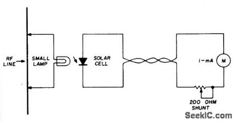
A suitable pilot lamp is illuminated by a small sample of rf and energizes an inexpensive solar cell; the dc current generated by the cell is a measure of relative rf power, and may be routed to a low-current meter located at any convenient point. A sensitive, low-current pilot lamp is desirable to cause minimum dis-turbance to normal rf circuit conditions. The number 48 or 49, 60 mA lamp is suitable for use with transmitters above 1-watt output. (View)
View full Circuit Diagram | Comments | Reading(0)
REMOTE_AIVIPLIFIER
Published:2009/6/18 22:02:00 Author:May
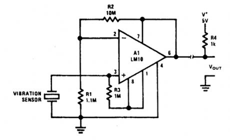
Useful for transducers and such where a sin-gle two-wire pair are the only leads available. (View)
View full Circuit Diagram | Comments | Reading(947)
REMOTE_CONTROL_TRANSMITTER
Published:2009/6/17 23:07:00 Author:May

This transmitter can be used for a variety of purposes. An INS8048L microprocessor generates various codes depending on keypad presses. The codes are modulated on a 40-kHz carrier. Q1 drives IR LEDs LED1 and LED2. (View)
View full Circuit Diagram | Comments | Reading(1206)
ULTRASONIC_REMOTE_CONTROL_TRANSMITTER
Published:2009/6/17 23:04:00 Author:May
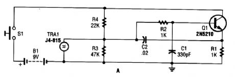
A GC Electronic P/N J4-815 ultrasonic transducer is used in this 40-kHz transmitter for remote-control application. (View)
View full Circuit Diagram | Comments | Reading(1182)
REMOTE_CONTROL_EXTENDER
Published:2009/6/17 23:03:00 Author:May
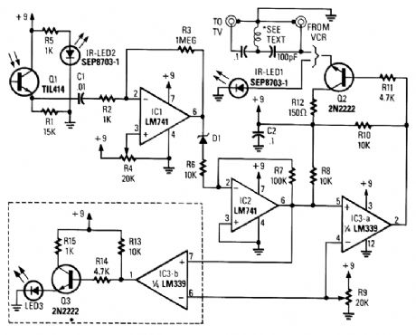
A signal from an IR remote control is converted from IR radiation to a frequency pulse that can be transmitted through coaxial TV cable or any other two-conductor wire to another room, where it's converted back into an IR signal. (View)
View full Circuit Diagram | Comments | Reading(1635)
INTERFACE_CIRCUITS_FOR_THE_REMOTE_CONTROL_TRANSMITTER
Published:2009/6/17 22:55:00 Author:May
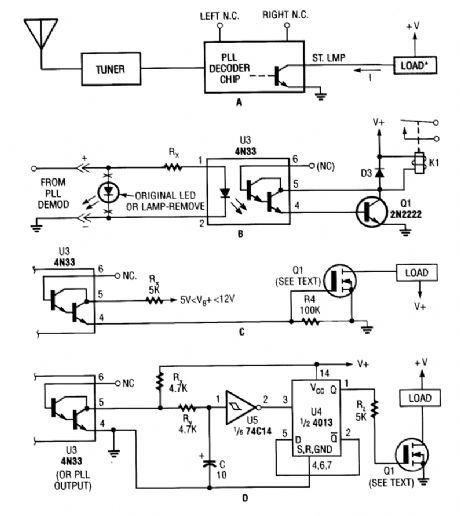
Shown here are several possible interface circuits that can be used with the remote-control transmitter. The one in A illustrates a typical FM stereo MUX decoder with a load connected directly to the open-collector output of a TA7343 PLL. The circuit in B illustrates an optoisolator-coupler out-put driving a 12-V relay coil via a general-purpose transistor. C shows the gate of an N-channel power MOSFET connected to the output of a 4N33. The final circuit, D, is a toggle flip-flop that allows push-on/push-off control. (View)
View full Circuit Diagram | Comments | Reading(2643)
REMOTE_CONTROL_RECEIVER
Published:2009/6/17 22:53:00 Author:May
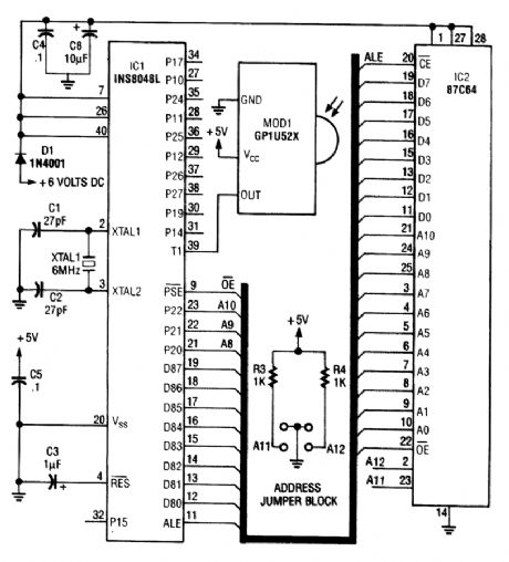
This circuit is based on the Sharp GP1U52X IR module and INS8048L microprocessor. The GP1U52X is a hybrid IC/infrared detector that provides a strong clean signal for later filtering and demodulation. (View)
View full Circuit Diagram | Comments | Reading(1399)
| Pages:12/34 1234567891011121314151617181920Under 20 |
Circuit Categories
power supply circuit
Amplifier Circuit
Basic Circuit
LED and Light Circuit
Sensor Circuit
Signal Processing
Electrical Equipment Circuit
Control Circuit
Remote Control Circuit
A/D-D/A Converter Circuit
Audio Circuit
Measuring and Test Circuit
Communication Circuit
Computer-Related Circuit
555 Circuit
Automotive Circuit
Repairing Circuit