
Remote Control Circuit
Index 14
M708 (TV) infrared remote control launch circuit
Published:2011/7/20 6:41:00 Author:Christina | Keyword: infrared, remote control, launch, TV
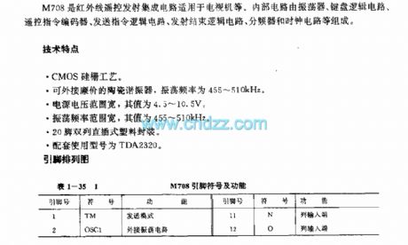
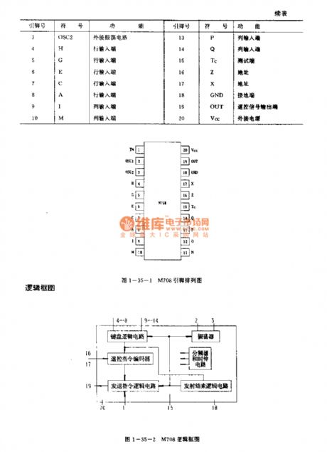
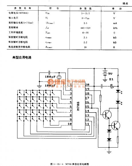
The M708 is designed as one kind of infrared remote control launch circuit that can be used in TV. The internal circuit is composed of the oscillator, the keyboard logic circuit, the sending command logic circuit, the transmitter ending logic circuit, the frequency divider and the clock cirucit.
Features
The CMOS silicon gate processThe external cheap ceramic resonator, the oscillation frequency is 455-510kHzThe wide oscillation frequency range, the value is 455-510kHzThe 20-pin dual-row DIP plastic packageThe matching model is TDA2320.
(View)
View full Circuit Diagram | Comments | Reading(1312)
PT2265 general infrared remote control coding circuit
Published:2011/7/20 6:52:00 Author:Christina | Keyword: general, infrared, remote control, coding circuit

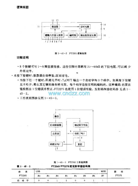
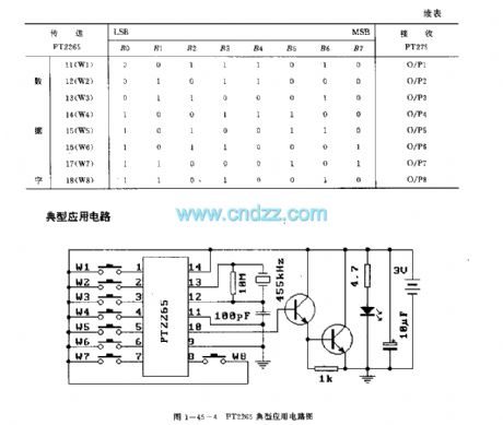
The PT2265 is designed as one kind of general infrared remote control coding circuit that can be used in the remote control transmitters. The internal circuit is composed of the oscillator, the timing circuit, the keyboard input scanning and sampling circuit, the coder and the output wave-form generator.
Features
The low power consumptionThe power supply voltage is 2.2-5.5VEight signal launch channelsThe start word can be encodedThe special coding techniques to improve the anti-noise ability14-pin dual-row DIP packageThe matching model is PT2275.
(View)
View full Circuit Diagram | Comments | Reading(1431)
SAAl250 (TV) infrared remote control launch circuit
Published:2011/7/20 7:12:00 Author:Christina | Keyword: TV, infrared, remote control, launch circuit
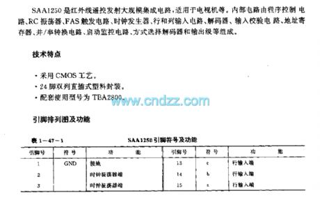
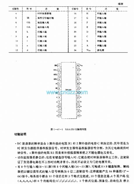
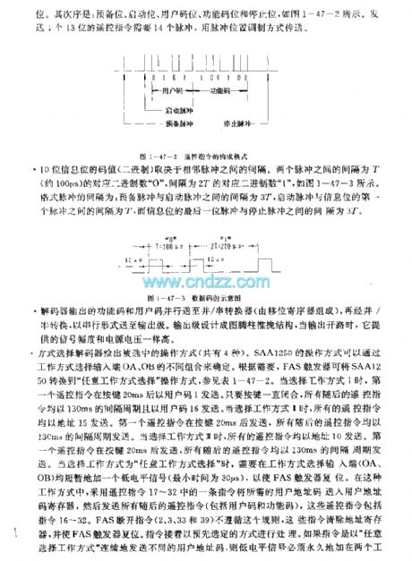
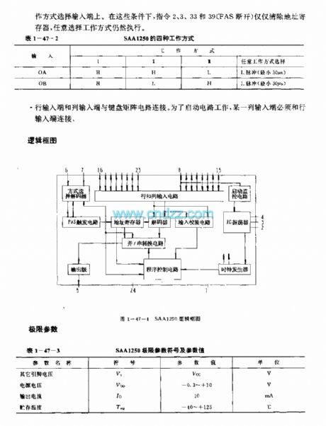
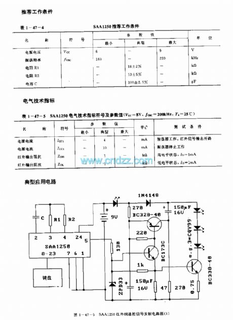
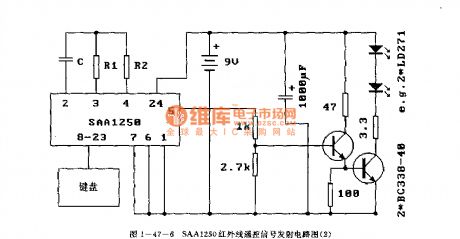
The SAAl250 is designed as one kind of infrared remote control launch circuit that can be used in the TVs. The internal circuit is composed of the program control circuit, the RC oscillator, the FAS trigger circuit, the clock generator, the row and column input circuit, the decoder, the input calibration circuit, the address register, the parallel/serial conversion circuit, the monitoring circuit, the mode selection decoder and the output stage.etc.
Features
It uses the CMOS technology,The 24-pin dual-row DIP plastic package,The matching model is TBA2800.
The frequency of the RC oscillator is decided by the pin-3's external resistor R1 and pin-2's external resistor C, the function of it is to supply the reference oscillation signal to the clock generator.
(View)
View full Circuit Diagram | Comments | Reading(1512)
SAA3004 infrared remote control launch circuit
Published:2011/7/20 8:15:00 Author:Christina | Keyword: infrared, remote control, launch circuit
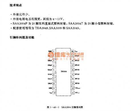
Features
The little external components.The wide external power supply voltage range, the value is 4-11V.The SAA3004P uses the 20-pin dual-row DIP plastic package, the SAA3004T uses the 20-pin small size plastic package.The matching model are TDA3048, SAA3009 and SAA3049.
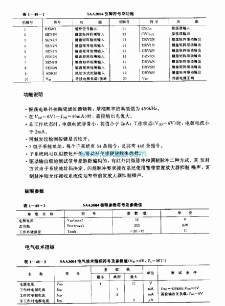
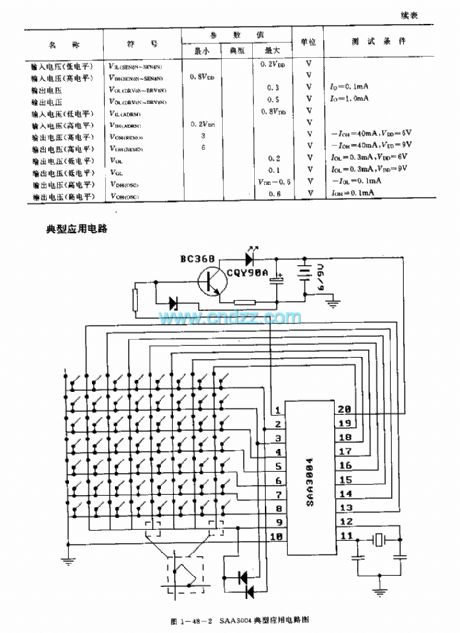
Function description
The oscillating circuit has the external ceramic filter. The typical value of the reference frequency is 450kHz.When the VDD=6V, the remote control output current is the maximum.In the non-operating state, the power supply current is very small, the value is lower than 2uA; in the operating state, the power supply current is lower than 2mA.It has seven groups of subsystem addresses, every subsystem has 64 instructions.
(View)
View full Circuit Diagram | Comments | Reading(2294)
SAA3010 (TV) infrared remote control launch circuit
Published:2011/7/20 7:43:00 Author:Christina | Keyword: infrared, remote control, launch circuit, TV

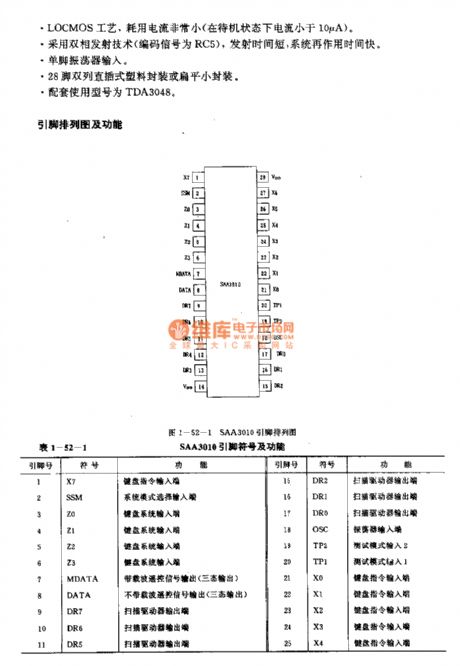
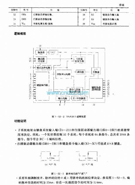
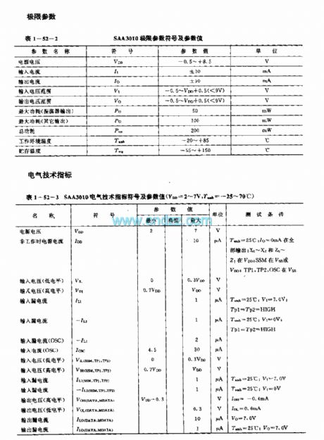
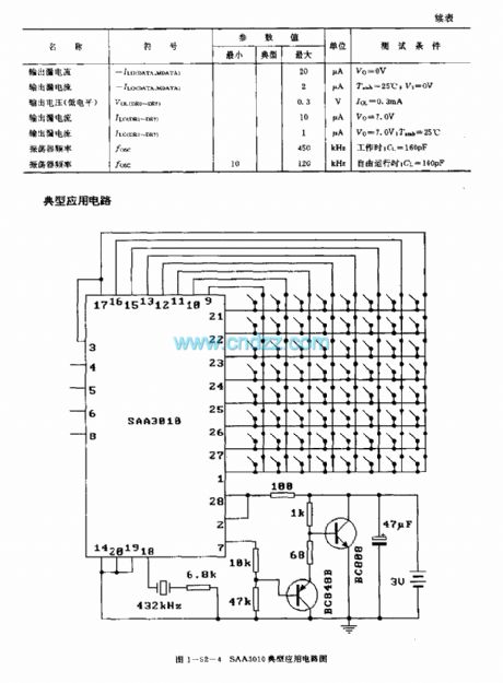
The SAA3010 is designed as one kind of low voltage power supply general general infrared remote control launch circuit. The internal circuit is composed of the oscillator, the test mode circuit, the mode selection circuit, the keyboard encoder, the control unit circuit, the decoder, the keyboard driver decoder, the instruction and system address latch and the frequency divider.
Features
Low voltage power supply, the power consumption is very small,It uses the dual-phase launch technology, the launch time is short,The single pin oscillator input,Every button of the keyboard is the single-pole switch,28-pin dual-row DIP plastic package,The matching model are TDA3048.
(View)
View full Circuit Diagram | Comments | Reading(3225)
IX0187PA (TV and audio equipment) 30 functions infrared remote control launch circuit
Published:2011/7/21 1:37:00 Author:TaoXi | Keyword: TV, audio equipment, 30 functions, infrared, remote control, launch circuit
The IX0187PA has the same features, pin arrangement, pin functions, absolute maximum ratings, electrical specifications, logic diagram and the typical applications with the M58484P, so they can directly exchange. (View)
View full Circuit Diagram | Comments | Reading(974)
IX033lPA (video tape recorder) infrared remote control launch circuit
Published:2011/7/20 19:08:00 Author:TaoXi | Keyword: video tape recorder, infrared, remote control, launch circuit
The IX033lPA has the same features, pin arrangement, pin functions, absolute maximum ratings, electrical specifications, logic diagram and the typical applications with the LR3710AM, so they can directly exchange. (View)
View full Circuit Diagram | Comments | Reading(820)
IX0348PA (video tape recorder) infrared remote control launch circuit
Published:2011/7/20 19:09:00 Author:TaoXi | Keyword: video tape recorder, infrared, remote control, launch circuit
The IX0348PA has the same features, pin arrangement, pin functions, absolute maximum ratings, electrical specifications, logic diagram and the typical applications with the LR3709, so they can directly exchange. (View)
View full Circuit Diagram | Comments | Reading(840)
Ix0478PA (video tape recorder) infrared remote control launch circuit
Published:2011/7/20 19:10:00 Author:TaoXi | Keyword: video tape recorder, infrared, remote control, launch circuit
The IX0478PA has the same features, pin arrangement, pin functions, absolute maximum ratings, electrical specifications, logic diagram and the typical applications with the LR3714M, so they can directly exchange. (View)
View full Circuit Diagram | Comments | Reading(858)
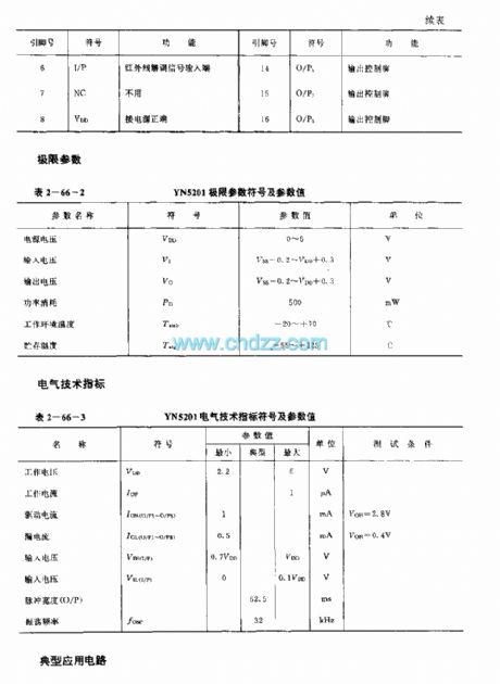
YN5201 (electric fan) infrared remote control decoder circuit
Published:2011/7/21 3:36:00 Author:TaoXi | Keyword: electric fan, infrared, remote control, decoder circuit
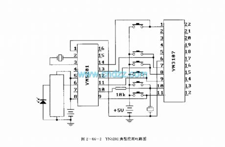
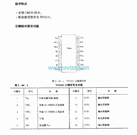
Features
It uses the CMOS technology;The matching model is YN5101.
(View)
View full Circuit Diagram | Comments | Reading(1144)
YH5203 (anti-theft system) radio or infrared remote control decoder circuit
Published:2011/7/21 3:46:00 Author:TaoXi | Keyword: anti-theft system, radio, infrared, remote control, decoder circuit
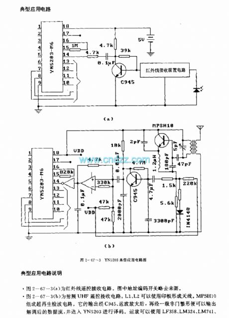
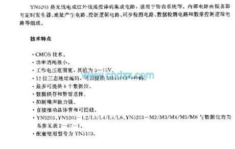
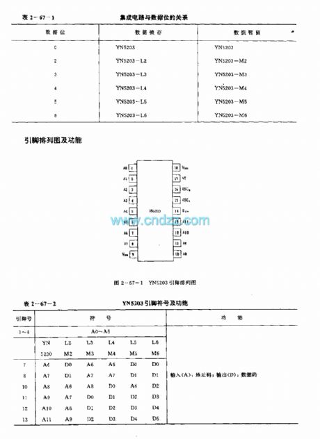
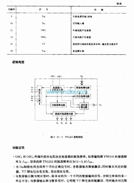
The YH5203 is designed as one kind of radio or infrared remote control decoder circuit that can be used in the anti-theft system. The internal circuit is composed of the oscillator, the timing generator circuit, the address generator, the control logic circuit, the synchronous detection circuit, the data detection circuit and the data control logic circuit.
Features
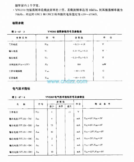
The CMOS technology.The power consumption is low.The operating voltage range is wide, the value is 3-15V.The 12-bit three states address coding can supply 531441 kinds of code.The six data position.The data latching and persistence selection.The strong ability to reduce the noise. It can promote the transistor and SCR directly.The matching model is YN5103.
(View)
View full Circuit Diagram | Comments | Reading(1527)
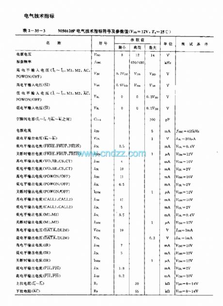
M50120P (TV) infrared remote control launch circuit
Published:2011/7/20 19:38:00 Author:TaoXi | Keyword: TV, infrared, remote control, launch circuit
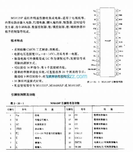
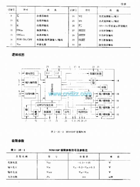
The M50120P is designed as one kind of infrared remote control launch circuit that can be used in TVs. The internal circuit is composed of the input circuit, the scanning circuit, the type coding circuit, the oscillator, the timing signal generator, the instruction decoder, the data controller, the D/A controller, the D/A converter and the program controller.
Features
It uses the aluminum gate CMOS technology;When it uses the single power operating mode, the power voltage is wide (Vcc=8-14V);The oscillation circuit is connected with the ceramic or the LC component to be used as the resonant component, the transmitting signal uses the pulse code modulation mode;It can receive 36 kinds of instructions, and it has nine direct key functions;The simple single frequency receiving system;30-pin dual-row DIP package;The matching models are M51231P, M58486AP or the M50118P.
(View)
View full Circuit Diagram | Comments | Reading(1324)
M50119F (TV) infrared remote control launch circuit
Published:2011/7/20 19:22:00 Author:TaoXi | Keyword: TV, infrared, remote control, launch circuit
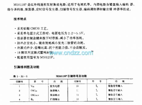

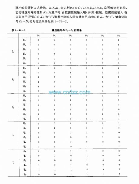
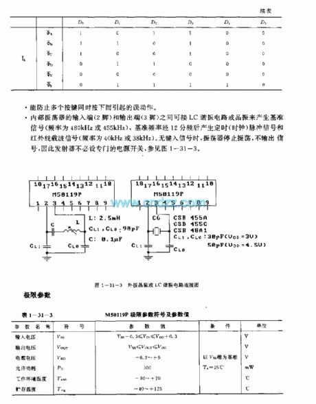
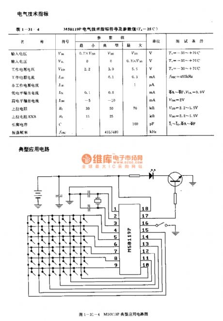
M50119P is designed as one kind of infrared remote control launch circuit that can be used in the TVs. The internal circuit is composed of the keyboard input encoder, the instruction decoder, the oscillator, the timing signal generator, the scanning signal generator, the coding modulator and the output buffer.
Features
It uses the aluminum gate CMOS technology;When it uses the single power operating mode, the power voltage is 2.2-5.5V;When the keyboard button is not pressed, the oscillator will stop oscillating to save the power comsumption;The duty ratio is small to reduce the power comsumption;The little external components, high signal to noise ratio, strong anti-interference ability;18-pin dual-row DIP plastic package;The matching model is M50120P.
(View)
View full Circuit Diagram | Comments | Reading(1436)
M50125P (TV) 30 functions infrared remote control launch circuit
Published:2011/7/20 19:26:00 Author:TaoXi | Keyword: 30 functions, infrared, remote control, launch circuit, TV
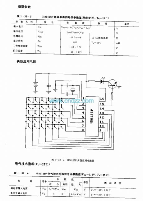
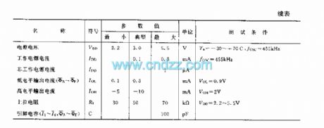
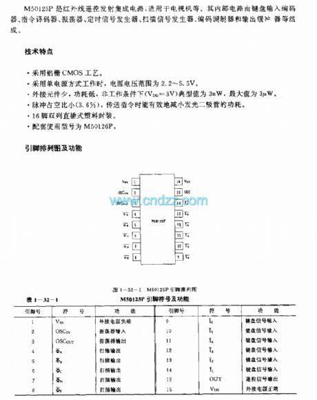
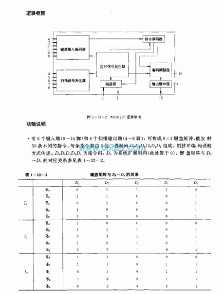
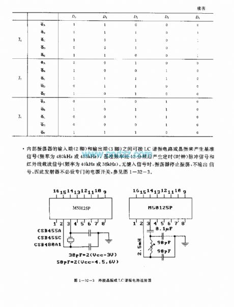
M50125P is designed as one kind of infrared remote control launch circuit that can be used in the TVs. The internal circuit is composed of the keyboard input encoder, the instruction decoder, the oscillator, the timing signal generator, the scanning signal generator, the coding modulator and the output buffer.
Features
It uses the aluminum gate CMOS technology;When it uses the single power operating mode, the power voltage is 2.2-5.5V;When the keyboard button is not pressed, the oscillator will stop oscillating to save the power comsumption;The duty ratio is small (3.6%) to reduce the power comsumption of the LED;The little external components, high signal to noise ratio, strong anti-interference ability;16-pin dual-row DIP plastic package;The matching model is M50126P.
(View)
View full Circuit Diagram | Comments | Reading(1141)
AN5020 (TV and video recorder) infrared remote control receiving preamplifier circuit
Published:2011/7/20 21:58:00 Author:TaoXi | Keyword: TV, video recorder, infrared, remote control, receiving, preamplifier circuit
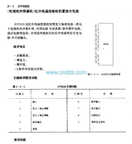
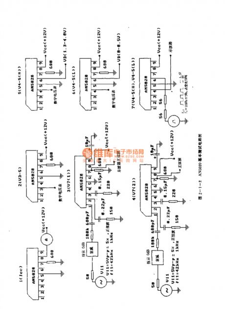
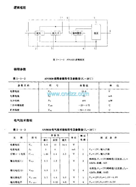
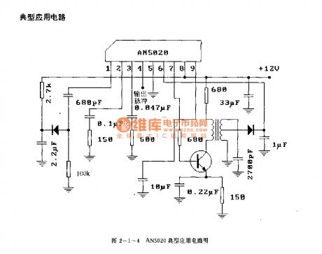
The AN5020 is designed as one kind of infrared remote control receiving preamplifier circuit that can be used in the TV and video recorder. The internal circuit is composed of the amplifier, the pulse shaping circuit, the voltage stabilization amplifier, the function of it is to change the infrared remote control signal into the pulse square wave output.
Features
High sensitivity,Large gain,Low noise,9-pin single row DIP package.
(View)
View full Circuit Diagram | Comments | Reading(2139)
BA2206 (toy car and motorboat) wireless remote control servo system single-chip circuit
Published:2011/7/20 22:22:00 Author:TaoXi | Keyword: toy car, motorboat, wireless, remote control, servo system, single-chip circuit

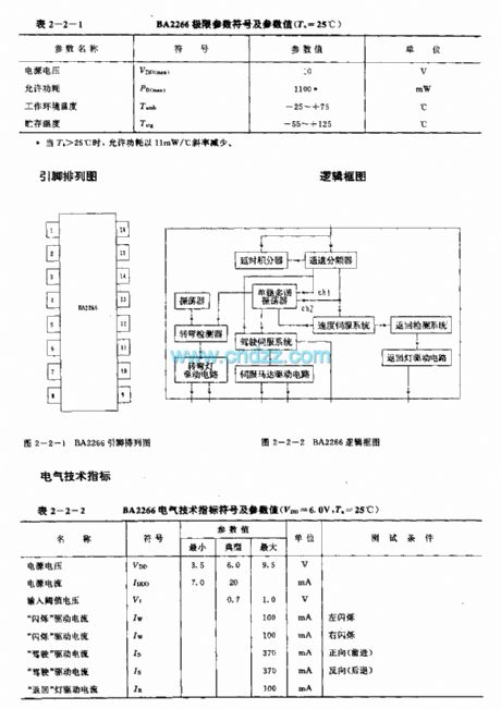
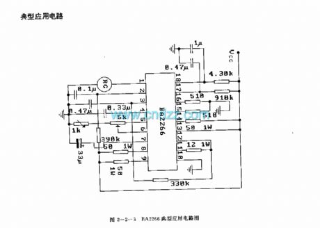
The BA2206 is designed as one kind of wireless remote control servo system single-chip circuit that can be used in the toy car, motorboat or other mobile electronic toys. The internal circuit is composed of the oscillator, the delay integrator, the channel frequency divider, the turning detector, the driving servo system, the speed servo system, the return detection system and a variety of drive circuits. It is in the 18-pin dual-row DIP plastic package.
The motor speed control includes the multi-function control such as the forward drive and back driver.The left and right flashing lights are connected with the output port of the driving servo system, the pulse signal controls the automatic flashing.The flashing light's flashing cycle can be changed by changing the value of external capacitor.
(View)
View full Circuit Diagram | Comments | Reading(3762)
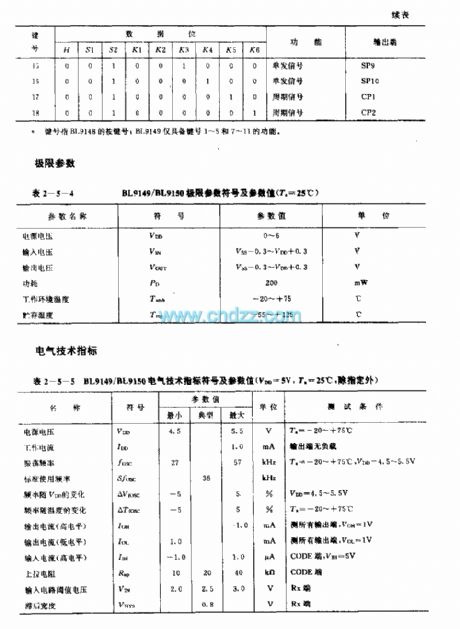
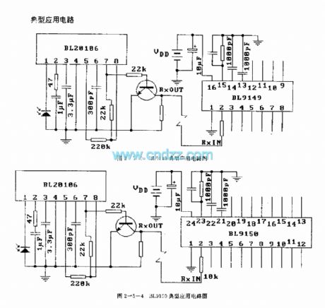
BIJ9149/BIJ9150 general infrared control receiving circuit
Published:2011/7/20 22:53:00 Author:TaoXi | Keyword: general, infrared, control, receiving circuit
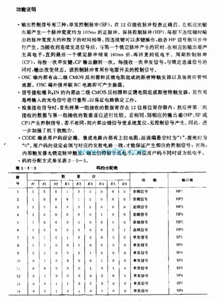
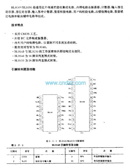
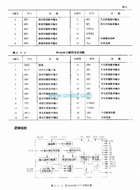
Function description
There are three kinds of output control signals: the single control pulse (SP), after the 12-bit receiving pulse is correct, the corresponding output port will produce a positive pulse with the pulse width of 107ms. if you maintain the control pulse (HP), when you press the continuous button, the output pulse width is equal to the press time. The HP signals can be synchronously parallel produced because the continuous key has the multi-key operation function, when it receives the continuous signal, the high level is produced by the corresponding output port.
(View)
View full Circuit Diagram | Comments | Reading(950)
uPDl987C (TV) infrared remote control receiving circuit
Published:2011/7/21 2:18:00 Author:TaoXi | Keyword: TV, infrared, remote control, receiving circuit
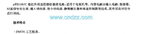
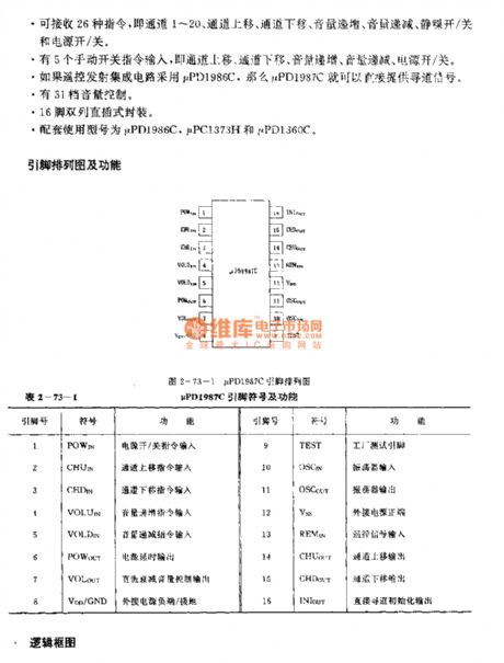
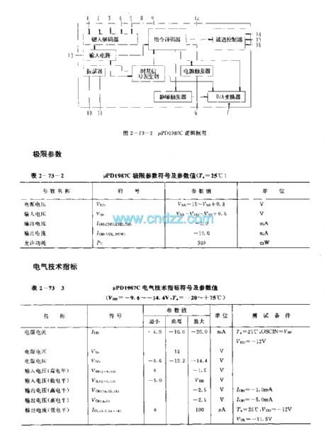
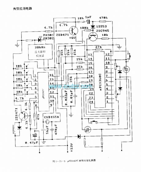
The uPDl987C is designed as the infrared remote control receiving circuit that can be used in the TVs. The internal circuit is composed of the input circuit, the oscillator, the time-base signal generator, the type-in decoder, the instruction decoder, the squelch trigger, the channel controller. The function of it is to decode the signal.
Features
The PMOS technology.It can receive 26 kinds of instructions.It has five manual switches to input the instructions.It has 31 stages of volume control.The 16-pin dual-row DIP package.The matching models are uPD1986C, uPC1373H and the uPD1360C.
(View)
View full Circuit Diagram | Comments | Reading(1080)
The uPDl937C (TV sets) infrared remote control receiving circuit
Published:2011/7/21 2:20:00 Author:TaoXi | Keyword: TV sets, infrared, remote control, receiving circuit

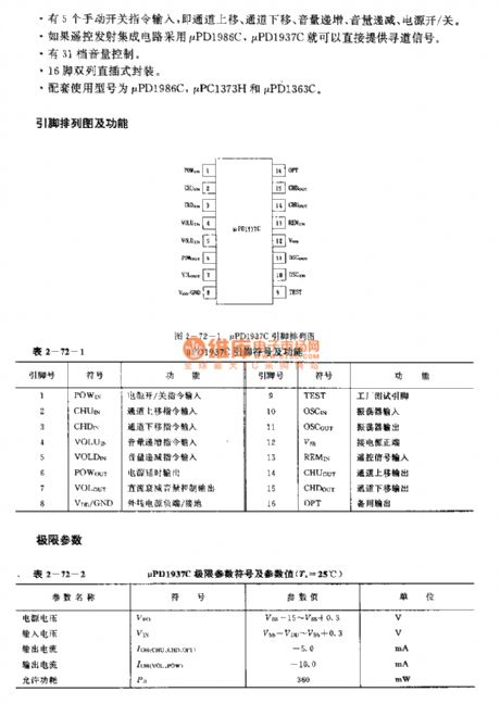
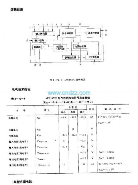
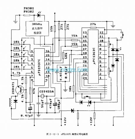
The uPDl987C is designed as the infrared remote control receiving circuit that can be used in the TVs. The internal circuit is composed of the input circuit, the oscillator, the time-base signal generator, the type-in decoder, the instruction decoder, the squelch trigger, the channel controller. The function of it is to decode the signal.
Features
The PMOS technology.It can receive 26 kinds of instructions.It has five manual switches to input the instructions.It has 31 stages of volume control.The 16-pin dual-row DIP package.The matching models are uPD1986C, uPC1373H and the uPD1360C.
(View)
View full Circuit Diagram | Comments | Reading(1312)
UPCI490HA (TV) infrared remote control receiving signal processing circuit
Published:2011/7/21 3:11:00 Author:TaoXi | Keyword: TV, infrared, remote control, receiving, signal, processing circuit
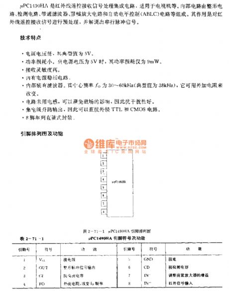
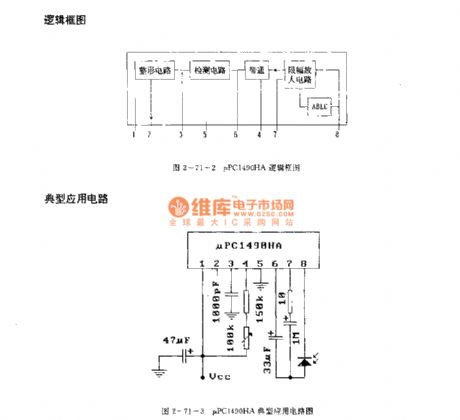
The μPCI490HA is designed as one kind of infrared remote control receiving signal processing circuit that can be used in the TVs. The internal circuit is composed of the shaping circuit, the detection circuit, the bandpass filter, the limiting amplifier and the automatic level control (ABLC) circuit. The function of it is to pretreat the infrared remote control receiving signal and demodulate out the serial pulse signal.
Features
Low power supply voltage, the typical value is 5V.Low power comsumption, when the power supply voltage is 5V, the power comsumption is 9mW.The high receiving sensitivity. It has the power voltage stabilization circuit.It has the filter. The center frequency fo is 30-60kHz (the typical value is 38kHz).The circuit has no electrical inductance to avoid the influence of the magnetic field.8-pin single row DIP package.
(View)
View full Circuit Diagram | Comments | Reading(1062)
| Pages:14/34 1234567891011121314151617181920Under 20 |
Circuit Categories
power supply circuit
Amplifier Circuit
Basic Circuit
LED and Light Circuit
Sensor Circuit
Signal Processing
Electrical Equipment Circuit
Control Circuit
Remote Control Circuit
A/D-D/A Converter Circuit
Audio Circuit
Measuring and Test Circuit
Communication Circuit
Computer-Related Circuit
555 Circuit
Automotive Circuit
Repairing Circuit