
Remote Control Circuit
Index 15
Highly Reliable Generic Timer Circuit
Published:2011/7/14 8:37:00 Author:Joyce | Keyword: Highly Reliable, Generic , Timer
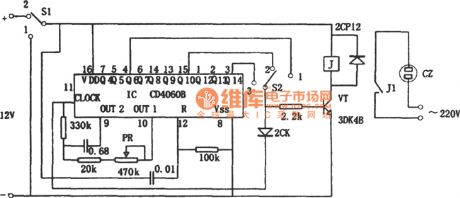
As shown in the figure is a highly reliable generic timing circuit composed of CD4060B. The time of timing the circuit ranges from 1 second to 1 hour, which is controlled by switch S2 control with 3 gears, namely: when S2 is 1, time of timing is 1 ~ 20 seconds ; when S2 is 2, time of timing is 15 ~ 320 seconds; when S2 is 3, time of timing 4 ~ 85 minutes . PR can be used to calibrate the timing time. The timing mode is counting type. CD4060B is a binary 14-level counter. When S1 turns from 1 to 2, the circuit will automatically reset, and timing will start. At that time, J is not actuated, normally closed contact J1 will be on, and voltage on socket CZ will supply power. (View)
View full Circuit Diagram | Comments | Reading(1347)
Preset Outage Timer of Electric Cooker Circuit
Published:2011/7/14 8:38:00 Author:Joyce | Keyword: Preset, Outage , Timer , Electric Cooker
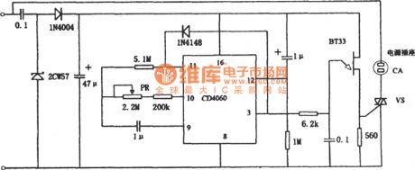
As shown in the figure is a preset outage timer of electric cooker circuit. Time of the timing circuit ranges from 1 hour to 12 hours, which can be regulated by PR .The timing mode is counting typeand control method mode is preset outage timing. The circuit uses BT33 to produce trigger signals of thyristor VS. If BT33 stops vibrating, VS will shut off, and CZ will be interrupted. (View)
View full Circuit Diagram | Comments | Reading(2519)
Infrared remote control circuits TR1300/1315 and PIC12043
Published:2011/7/18 21:48:00 Author:TaoXi | Keyword: Infrared remote control
The same to the digital coding circuit, the output coding of the jump yards coding circuit can be transmited by the infrared or radio waves. The modulation signal is amplified and demodulated by the receiving circuit and demodulating circuit at the receiving port, and this signal is sent out by the jump yards decoder chip, it controls the corresponding circuit by controlling the executive circuit. The infrared remote control circuit which is composed of the jump yards chip TR1300/1315 and the infrared remote control receiving module PIC12043 is as shown:
Infrared receiving demodulation decoding and output circuit:
(View)
View full Circuit Diagram | Comments | Reading(1017)
The Remote control automatic door circuit
Published:2011/7/18 21:47:00 Author:TaoXi | Keyword: Remote control, automatic door
Transmitter circuit:
Receiving circuit:
Three-phase positive &negative motor which is controlled by this circuit is as shown:
(View)
View full Circuit Diagram | Comments | Reading(1024)
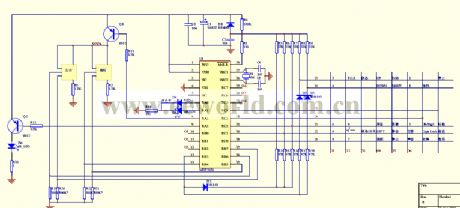
Sixteen-channel remote receiver circuit T998C
Published:2011/7/18 21:46:00 Author:TaoXi | Keyword: Sixteen-channel, remote receiver
The key components that will be used in this article:
T998C CD4514 9014
The sixteen-channel remote receiver circuit T998C which is composed of the T998C-12V receiving module and the four-sixteen-channel CD4514 decoder. This circuit can be used as the latch output and the unlatch output, SB is the control switch. When the SB is connected with the VDD, the circuit is in the latch output state, the sixteen output terminalsare not controlled by the Io output state; When the SB is connected with the VDD's output port, the circuit is in the unlatch output state, the output terminalsare controlled by the Io output state. When you are using this sixteen-channel remote receiver circuit, you must follow the two-decimal encoding method, and finish the operation of each channel with the code list. The remote operation code list of the transmitter's each channel is as shown:
(View)
View full Circuit Diagram | Comments | Reading(1428)
The Toy tank wireless remote control circuit HS101/HS201
Published:2011/7/18 21:47:00 Author:TaoXi | Keyword: Toy tank, wireless remote control
The toy tank coding emitter circuit:
The toy tank receiving decode circuit:
(View)
View full Circuit Diagram | Comments | Reading(933)
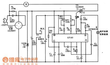
TL163 fan ultrasonic remote control integrated circuit diagram
Published:2011/7/20 20:14:00 Author:Ecco | Keyword: fan , ultrasonic , remote control , integrated circuit
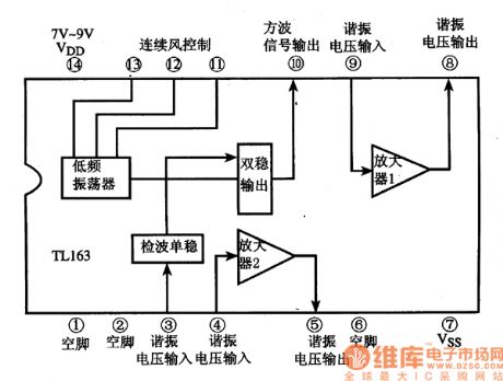
TL163 is a dedicated fan ultrasonic remote control integrated circuit, it is widely used in various high-end remote fan program control circuit. 1. Features TL163 integrated circuit includes two high-gain amplifier, detector, monostable trigger, low-frequency oscillator and bistable drive circuit. The block diagram of the circuit is shown in Figure 1. Figure 1 shows the circuit block diagram and pin functions of TL163 integrated circuit.
2. Pin function TL163 IC uses 14-pin dual in-line plastic package, the pin functions are shown in Figure 1. 3. A typical application circuit The ultrasonic remote control system typical application circuit composed of TL163 integrated circuit is shown in Figure 2. Figure 2 is TL163 IC's typical application circuit
(View)
View full Circuit Diagram | Comments | Reading(2035)
PC infrared remote control
Published:2011/6/30 21:52:00 Author:zj | Keyword: PC, infrared, remote control
View full Circuit Diagram | Comments | Reading(1045)
Long interval timer circuit
Published:2011/7/17 1:55:00 Author:Fiona | Keyword: Long interval, timer
Long interval timer circuit is shown as above:
(View)
View full Circuit Diagram | Comments | Reading(1530)
MC9481 (electronic toys) remote control transmitter coding circuit
Published:2011/7/18 7:17:00 Author:Christina | Keyword: electronic toys, remote control, transmitter, coding
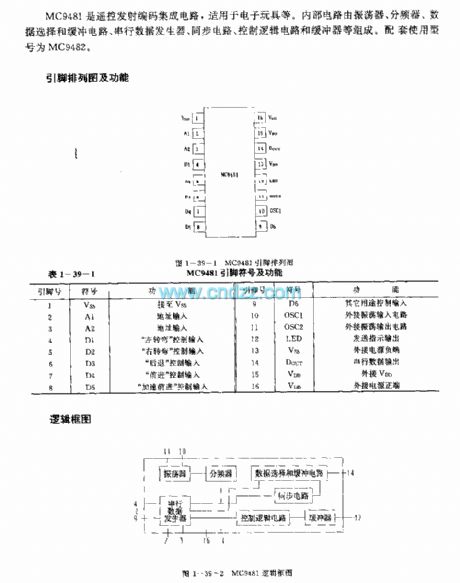
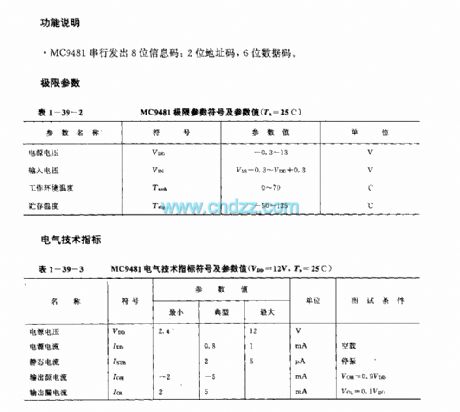
The MC9481 is designed as one kind of remote control transmitter coding circuit that can be used in the electronic toys. The internal circuit is composed of the oscillator, the frequency divider, the data selection and buffer circuit, the serial data generation circuit, the synchronous circuit, the logic control circuit and the buffer circuit. The matching model is MC9482.
(View)
View full Circuit Diagram | Comments | Reading(1362)
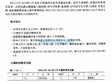
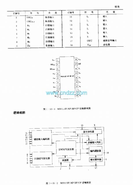
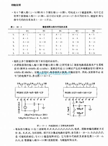
MC145030 (cordless phone and half-duplex remote controller) infrared ray, ultrasonic or RF remote control coding and decoding circuit
Published:2011/7/18 7:52:00 Author:Christina | Keyword: cordless phone, half-duplex, remote controller, infrared ray, ultrasonic, RF, remote control, coding, decoding
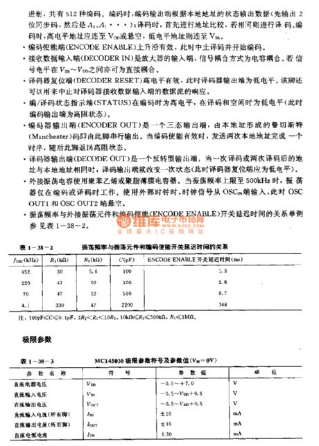
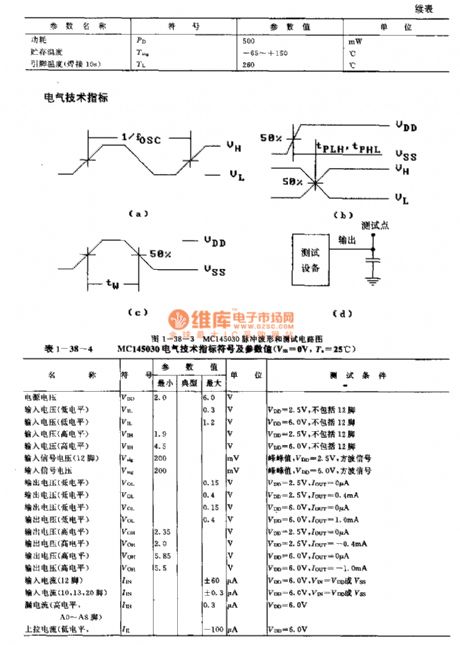
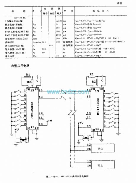
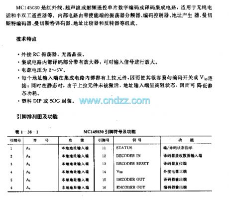
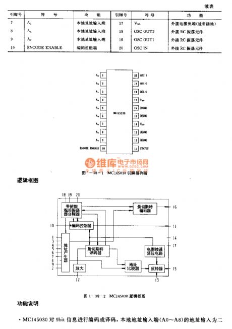
The MC145030 is designed as one kind of infrared ray, ultrasonic or RF remote control coding and decoding circuit that can be used in the cordless phone and half-duplex remote controller. The internal circuit is composed of the oscillator frequency divider with the enable pin, the coding remote controller, the address generator, the Manchester encoder, the Manchester coder, the address comparator and the reverse controller.
Features
It has the external RC oscillator;The internal decoding part of the integrated circuit has the amplifier to amplify the input signal;The power voltage is 2-6V;Every address port has the pull component in the IC;It is in the plastic DIP or SOG package.
(View)
View full Circuit Diagram | Comments | Reading(1507)
MC145026 general infrared ray, ultrasonic or RF remote control launch coding circuit
Published:2011/7/18 8:09:00 Author:Christina | Keyword: general, infrared ray, ultrasonic, RF, remote control, launch, coding circuit
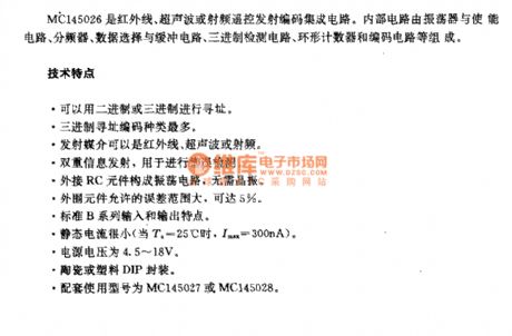
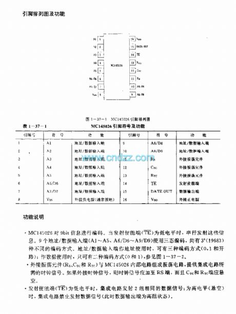
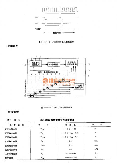
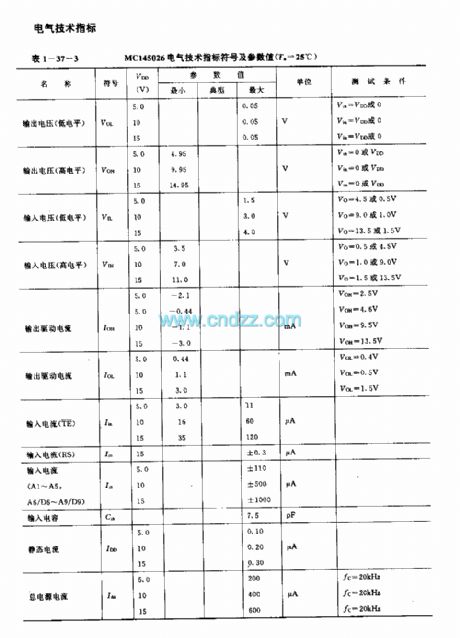
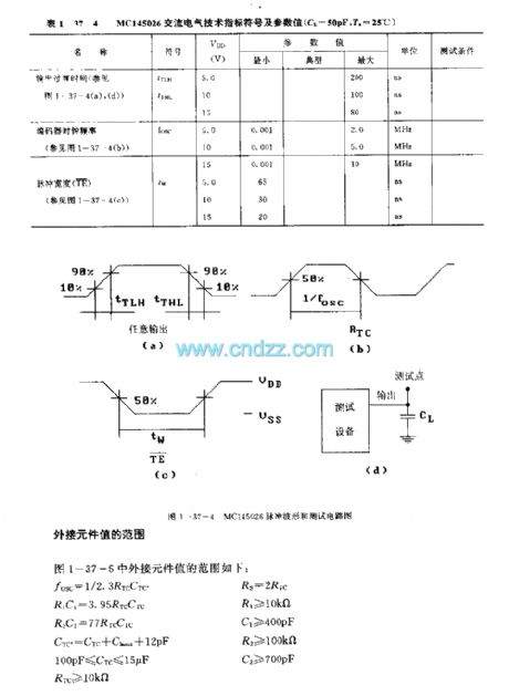
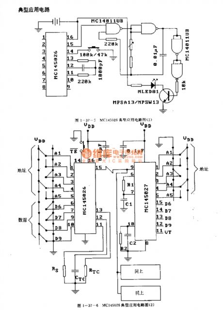
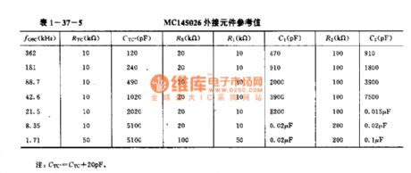
The MC145026 is designed as one kind of general infrared ray, ultrasonic or RF remote control launch coding circuit. The internal circuit is composed of the oscillator, the enable circuit, the frequency divider, the data selection and buffer circuit, the ternary detection circuit, the annular counter and the coding circuit.
Features
It uses the binary or ternary to find the address;The ternary addressing coding has the most kinds;The launch media can be the infrared ray, ultrasonic or the RF;The double information launch can be used to detect the error;The external RC components form the oscillating circuit, so there is no need of the crystal oscillator;The external components has the allowable error range of 5%.
(View)
View full Circuit Diagram | Comments | Reading(2796)
M58480P/M58484P (TV and stereo equipment) 30 functions infrared remote control launch circuits
Published:2011/7/18 8:25:00 Author:Christina | Keyword: TV, stereo equipment, 30 functions, infrared, remote control, launch circuit
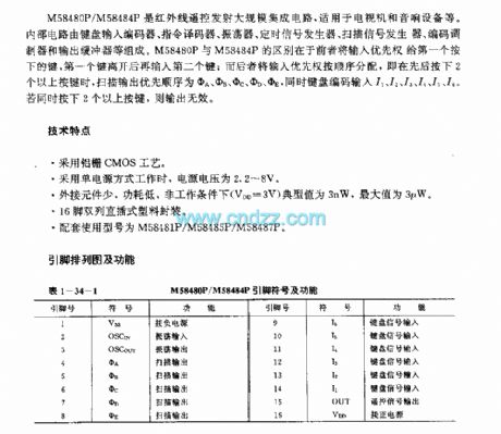
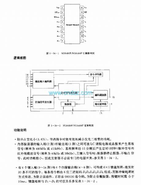
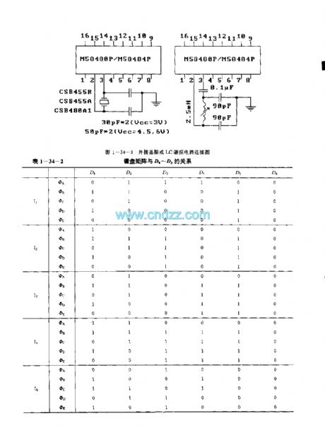
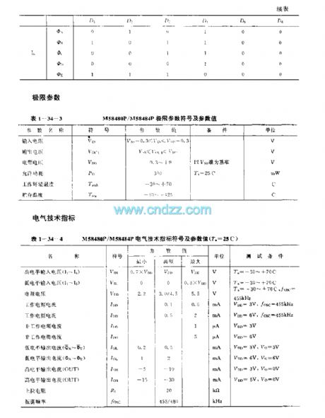
The M58480P and M58484P are designed as the 30 functions infrared remote control launch circuits that can be used in the TVs and stereo equipments. The internal circuit is composed of the keyboard input encoder, the instruction decoder, the oscillator, the timing signal generator, the scanning signal generator, the coding modulator and the output buffer. The difference between the M58480P and M58484P is that the M58480P gives the priority to the first button.
Features
It uses the aluminum gate CMOS technology;When it uses the single power operating mode, the power voltage is 2.2-8V;The external components are little, the power consumption is low, in the non-operating condition, the typical value is 3nW, the maximum value is 3uW;It is in the dual-row DIP plastic package;The matching models are M58481P/M58485P/M58487P.
(View)
View full Circuit Diagram | Comments | Reading(2616)
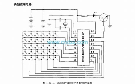
M50U5P/AF/BP/CP (video tape recorder, TV and stereo equipment) 120 functions infrared remote control launch circuits
Published:2011/7/18 8:37:00 Author:Christina | Keyword: video tape recorder, TV, stereo equipment, 120 functions, infrared, remote control, launch circuit
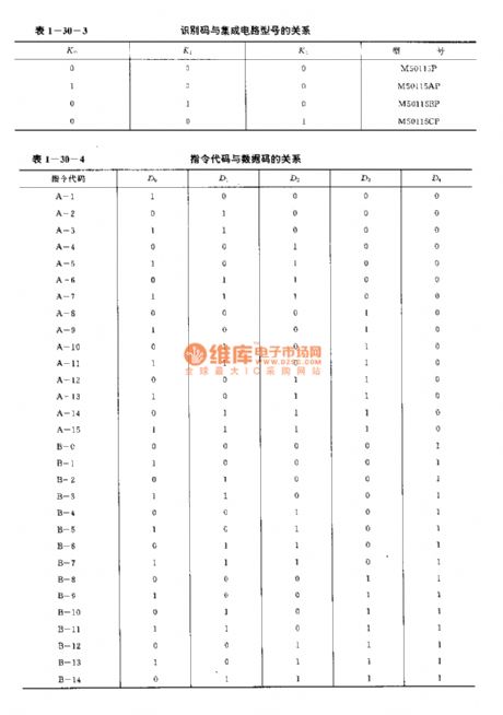
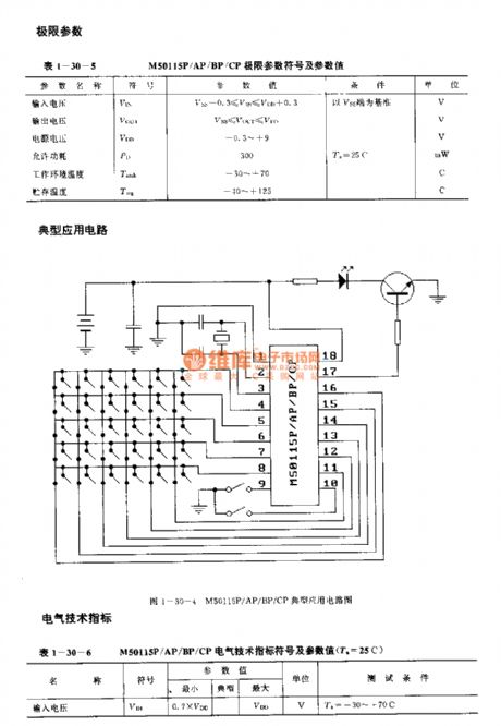
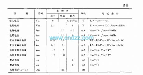
The M50U5P/AF/BP/CP are designed as the infrared remote control launch circuit that can be used in the video tape recorder, TV and stereo equipment applications. The internal circuit is composed of the keyboard input encoder, the instruction decoder, the oscillator, the timing signal generator, the scanning signal generator, the coding modulator and the output buffer. The difference between the M50115P, M50115AP, M50115BP, M50115CP is the identification code.
Features
It uses the single power operating mode, the power voltage is 2.2-8V;It uses the 18-pin dual-row DIP plastic package;When the keyboard button is not pressed, the oscillator will stop oscillating to reduce the power consumption;the pulse duty cycle is small;It has less external components, the SNR is high, the great anti-interference ability.
(View)
View full Circuit Diagram | Comments | Reading(1809)
M50142P (TV) infrared remote control launch circuit
Published:2011/7/18 8:46:00 Author:Christina | Keyword: TV, infrared, remote control, launch circuit
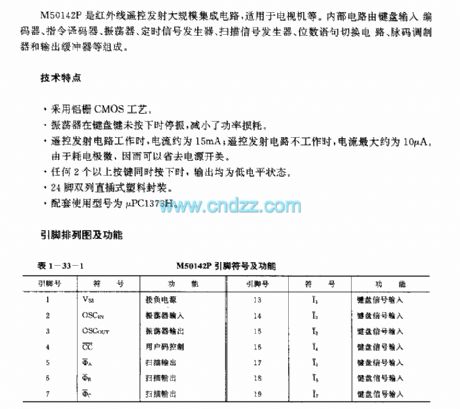
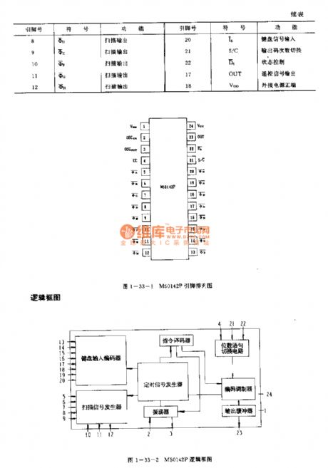
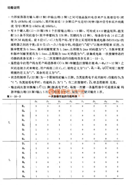
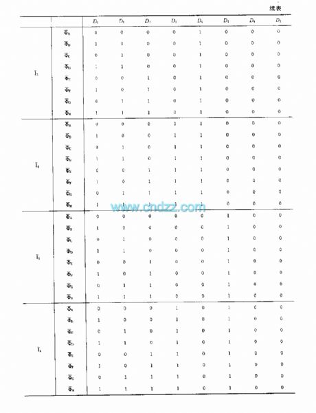
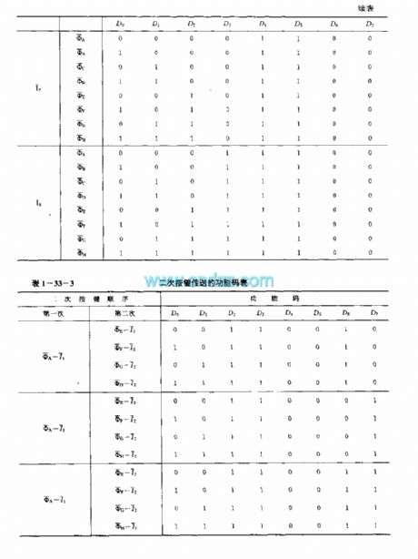
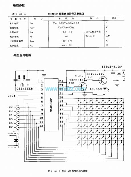
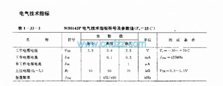
The M50142P is designed as one kind of infrared remote control launch large-scale circuit that can be used in the TVs. The internal circuit is composed of the keyboard input encoder, the instruction decoder, the oscillator, the timing signal generator, the scanning signal generator, the coding modulator and the output buffer.
Features
It uses the aluminum gate CMOS technology;When the keyboard button is not pressed, the oscillator will stop oscillating to reduce the power consumption;When the remote control launch circuit is operating, the current is about 15mA, when the remote control launch circuit is not operating, the current is about 10A;If you press any two or more buttons together, the output is in the low level state;It is in the 24-pin dual-row DIP plastic package;The matching model is uPC1373H.
(View)
View full Circuit Diagram | Comments | Reading(1499)
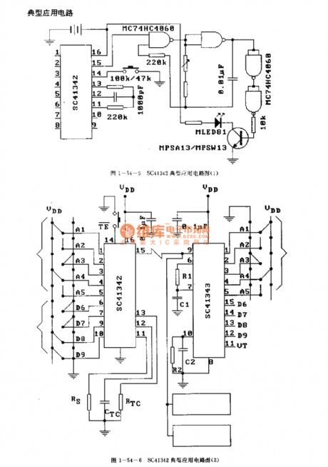
SC41343 general infrared, ultrasonic or RF remote control launch coding circuit
Published:2011/7/18 8:53:00 Author:Christina | Keyword: general, infrared, ultrasonic, RF, remote control, launch, coding
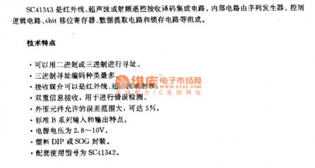
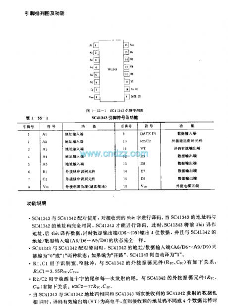
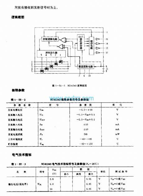
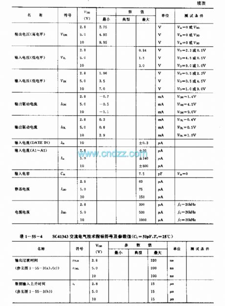
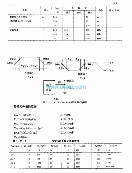
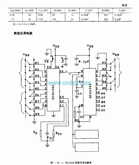
The SC41343 is designed as one kind of infrared, ultrasonic or RF remote control launch coding circuit. The internal circuit is composed of the sequence generator, control logic circuit,4-bit shift register,data extraction circuit and the latch circuit.
Features
It uses the binary or ternary to find the address;The ternary addressing coding has the most kinds;The launch media can be the infrared ray, ultrasonic or the RF;The double information launch can be used to detect the error;The external RC components form the oscillating circuit, so there is no need of the crystal oscillator;The external components has the allowable error range of 5%;The standard B series input and output features;The power voltage is 2.8-10V;The plastic DIP or SOG package;The matching model is SC41342.
(View)
View full Circuit Diagram | Comments | Reading(2146)
SC41344 general infrared, ultrasonic or RF remote control launch coding circuit
Published:2011/7/18 8:57:00 Author:Christina | Keyword: general, infrared, ultrasonic, RF, remote control, launch, coding
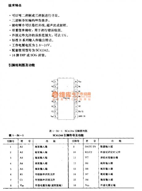
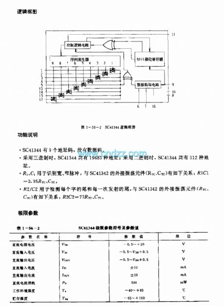
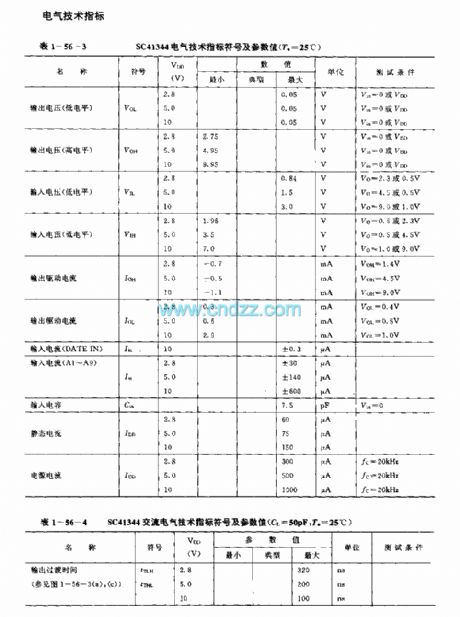
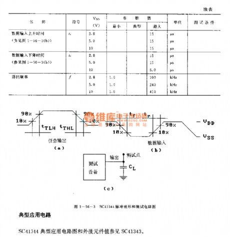
The SC41344 is designed as one kind of infrared, ultrasonic or RF remote control launch coding circuit. The internal circuit is composed of the sequence generator, control logic circuit,9-bit shift register,data extraction circuit and the latch circuit.
Features
It uses the binary or ternary to find the address;The ternary addressing coding has the most kinds;The launch media can be the infrared ray, ultrasonic or the RF;The double information launch can be used to detect the error;The external RC components form the oscillating circuit, so there is no need of the crystal oscillator;The external components has the allowable error range of 5%;The standard B series input and output features;The power voltage is 2.8-10V;The 16-pin DIP or SOG package;The matching model is SC41342.
(View)
View full Circuit Diagram | Comments | Reading(984)
SC41342 general infrared, ultrasonic or RF remote control launch coding circuit
Published:2011/7/18 9:01:00 Author:Christina | Keyword: general, infrared, ultrasonic, RF, remote control, launch, coding
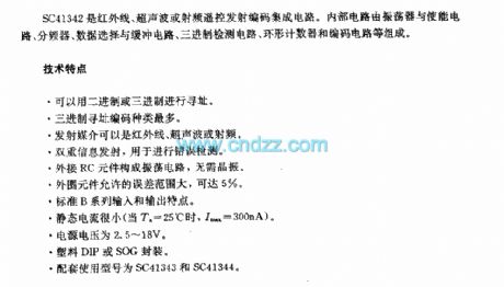
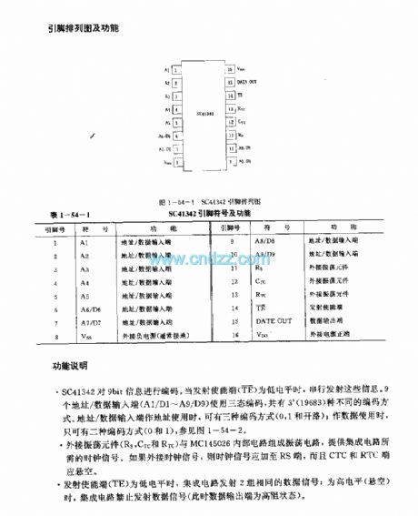
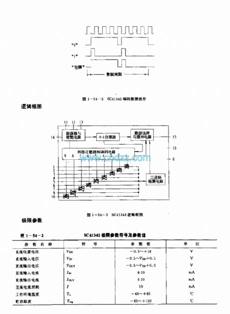
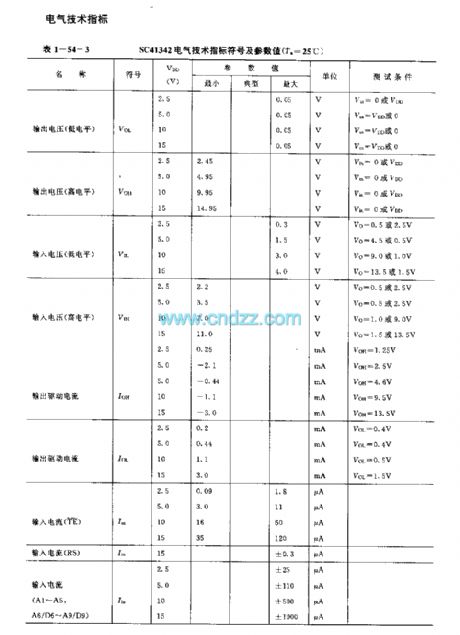
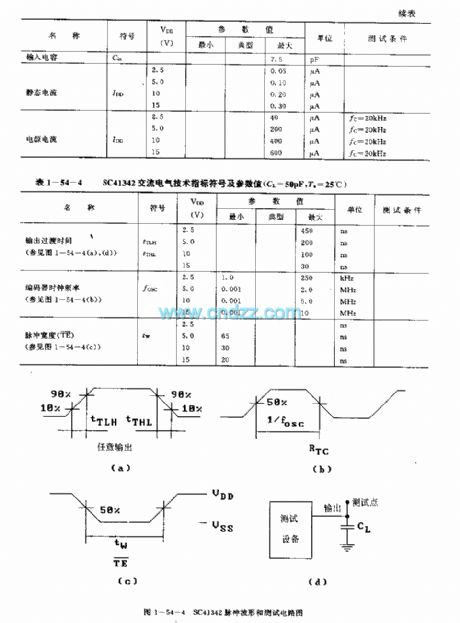
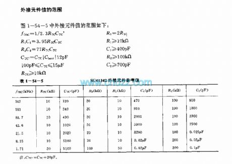
The SC41342 is designed as one kind of infrared, ultrasonic or RF remote control launch coding circuit. The internal circuit is composed of the oscillator, the enable circuit, the frequency divider, the data selection and buffer circuit, the ternary detection circuit, the annular counter and the coding circuit.
Features
It uses the binary or ternary to find the address;The ternary addressing coding has the most kinds;The launch media can be the infrared ray, ultrasonic or the RF;The double information launch can be used to detect the error;The external RC components form the oscillating circuit, so there is no need of the crystal oscillator;The external components has the allowable error range of 5%;The standard B series input and output features;The power voltage is 2.8-18V;The plastic DIP or SOG package;The static current is small;The matching model is SC41343 and the SC41344.
(View)
View full Circuit Diagram | Comments | Reading(1057)
Relay control for up-and-down slope circuit
Published:2011/7/12 9:54:00 Author:John | Keyword: Relay, up-and-down slope
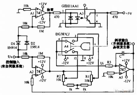
Relay control for up-and-down slope circuit is as shown, for which the DG387 CJ solid state relay has been used to achieve the switch from the upper slope to the lower slope. When the servo is at the new zero position, it slows down. The slope rate depends on the regulation position between R1 and R2. The circuit is with a low cost but to ensure the best response of the servo system. When input signal detected by A1 is not zero, the optical isolator A3 is started to drive the A4 to do the switch. Positive slope generated by A5 drives the system load to move towards the desired position. Thus, the control input voltage of servo feedback is driven to reduce input power.
(View)
View full Circuit Diagram | Comments | Reading(1533)
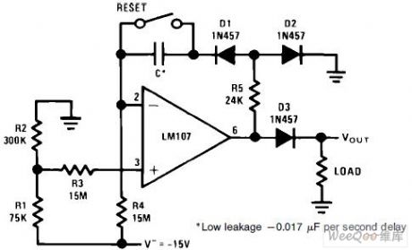
Small capacitance and long duration timer circuit
Published:2011/7/12 9:46:00 Author:John | Keyword: timer
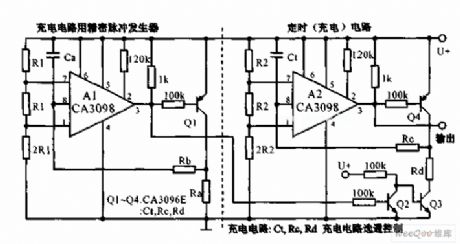
Small capacitance and long duration timer circuit is as shown. When a few hours of delay is needed, two dual-input precision level detectors CA3098 can be used. It is not necessary to use the high-capacity and low-leakage capacitor. If Rc = 22MΩ, RD = 100KΩ, 4 hours’ delay timer can be achieved as long as the CTK is 16μF.
(View)
View full Circuit Diagram | Comments | Reading(1305)
| Pages:15/34 1234567891011121314151617181920Under 20 |
Circuit Categories
power supply circuit
Amplifier Circuit
Basic Circuit
LED and Light Circuit
Sensor Circuit
Signal Processing
Electrical Equipment Circuit
Control Circuit
Remote Control Circuit
A/D-D/A Converter Circuit
Audio Circuit
Measuring and Test Circuit
Communication Circuit
Computer-Related Circuit
555 Circuit
Automotive Circuit
Repairing Circuit