
Remote Control Circuit
Index 10
YN5101 (electric fan) infrared remote control coding circuit
Published:2011/8/1 9:06:00 Author:TaoXi | Keyword: electric fan, infrared, remote control, coding circuit
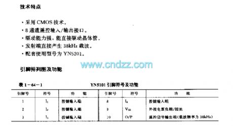
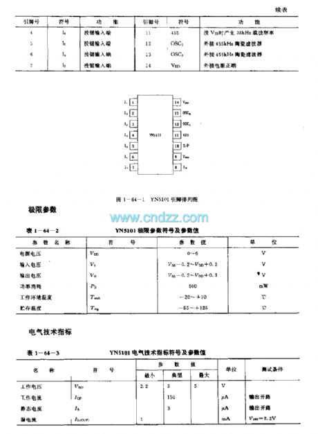
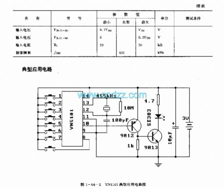
Features
It uses the CMOS technology.The 8-channel remote control output/input interface.The drive capability is strong, it can drive the transistor directly.The transmitter port produces the 38kHz carrier wave directly.The matching model is YN5201.
(View)
View full Circuit Diagram | Comments | Reading(2550)
Remote_control_of_ac_voltage
Published:2009/7/22 3:12:00 Author:Jessie
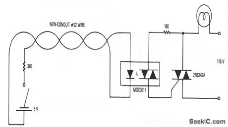
This circuit shows an MOC3011 optoisolator used for remote control of ac voltages. Local building codes frequently require that all 115-V light-switch wiring be enclosed in conduit. With this circuit, it is possible to control a large lighting load from a long distance through low-voltage (5 V) signal wiring, which is completely isolated from the ac line. Such wiring usually is not required to be in conduit, so the cost savings (especially in large commercial or residential build-ings) can be considerable. Although a lighting load is shown, the load can be a motor, fan, pool pump, etc. (View)
View full Circuit Diagram | Comments | Reading(1674)
TIME_CONSTANT_DETECTOR_FOR_TV_CONTROL
Published:2009/7/23 1:33:00 Author:Jessie
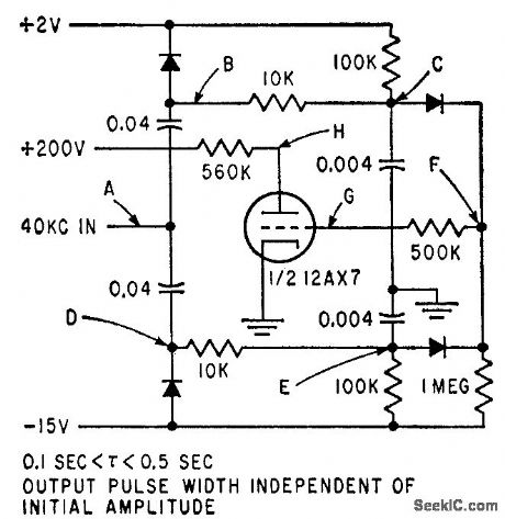
Produces output pulse whose width is proportional to time constant of exponentially damped ultrasonic signal, in range of 0.1 to 0.5 sec, independent of input amplitude.-K. R. Cross and R. O. Whitaker, Time-Constant Detectors Control Tv Sets, Electronics, 32:36, p 62-67. (View)
View full Circuit Diagram | Comments | Reading(1089)
TRANSMITTER_CONTROL_FOR_DRONE
Published:2009/7/22 20:45:00 Author:Jessie
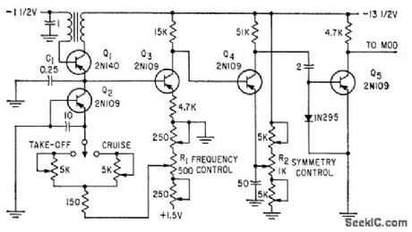
Pulse repetition rate and pulse symmetry control servos that drive rudder and elevator. Pulses modulate transmitter carrier, which is picked up and detected by super regenerative receiver in target drone.-G. B. Herzog, Transistors Simplify Control of Target Drone, Electronics, 32:18, p 52-54. (View)
View full Circuit Diagram | Comments | Reading(3835)
THREE_TONE_H_F_CONTROLS_TRANSMITTER_
Published:2009/7/22 21:24:00 Author:Jessie
Tone-modulated ground transmitter can be tone-modulated by three different tones, each corresponding to a particular reed of receiving relay and balloon. Consists of three stable audio oscillators (between 200 and 500 cps) and low-power crystal-controlled transmitter in h-f band between 3 and 18 Mc.-R. W. Frykman, Radio Command Set for High. Altitude Balloons, Electronics, 33:35, p 54-55. (View)
View full Circuit Diagram | Comments | Reading(1191)
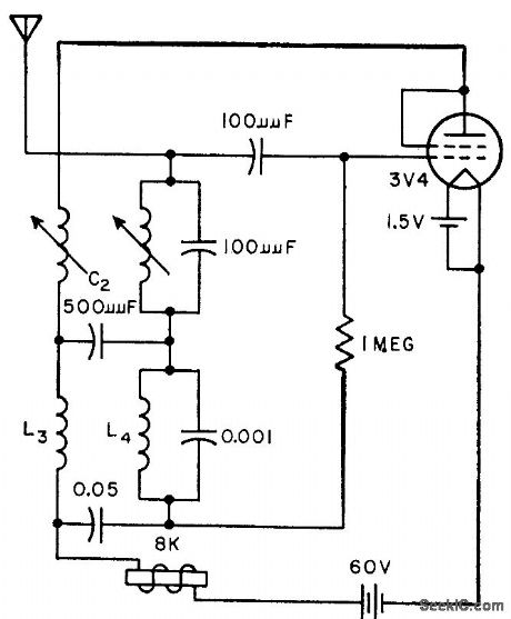
MILLER_SUPERREGENERATIVE_RECEIVER_
Published:2009/7/22 21:23:00 Author:Jessie
Well-known in model-control field for its reliability. With self-quenching, optimum performance is obtained when receiver is in weak oscillatory slate and incoming signal causes oscillation every third quench cycle. Provides large decrease in plate current when signal arrives.-S. J. Neshyba and F. E. Brooks, Jr., Stable Receiving Circuits for Remote Control, Electronics, 31:31, p 74-76. (View)
View full Circuit Diagram | Comments | Reading(1174)
UJT_TD_GARAGE_DOOR_CONTROL_TRANSMIT_TER
Published:2009/7/22 21:23:00 Author:Jessie
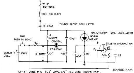
Unijunction tone oscillator modulates 27.255-Mc crystal-controlled tunnel-diode oscillator. Has adequate range for remote control of toys, window displays, garage doors, etc. When voice-modulated, can be used for short-range communication, as in shopping centers and bowling alleys, - Transistor Manual, Seventh Edition, General Electric Co., 1964, p 355.
(View)
View full Circuit Diagram | Comments | Reading(2949)
POLARITY_SENSING_ON_OFF_CONTROL
Published:2009/7/22 21:21:00 Author:Jessie
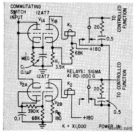
Remote switching circuits are sensitive to positive and negative inputs, thereby doubling number of control channels available from commutating switches of remote control sys tem for robot that performs jobs in danger ous radioactive areas. All functions requiring independent operation are connected to positive input circuits only.-D. A Campbell, Multiplex Circuits for Control of a Robot, Electronics, 33:4, p 46-48. (View)
View full Circuit Diagram | Comments | Reading(1043)
RECTANGULAR_WAVEFORM_GENERATOR
Published:2009/7/22 21:17:00 Author:Jessie
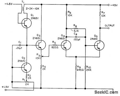
Povides variable frequency and symmetry without interaction of functions. Supply voltage can be -15 to -45 V. Frequency range is variable from 60 cps to 7 kc. Con be used to modulate small transmitter for remote control purposes.-L. E. Spadt, Rectangular Wove. form Generator, EEE, 10:6, p 33-34. (View)
View full Circuit Diagram | Comments | Reading(1072)
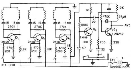
27255_MC_CONTROL_TRANSMITTER
Published:2009/7/22 21:05:00 Author:Jessie
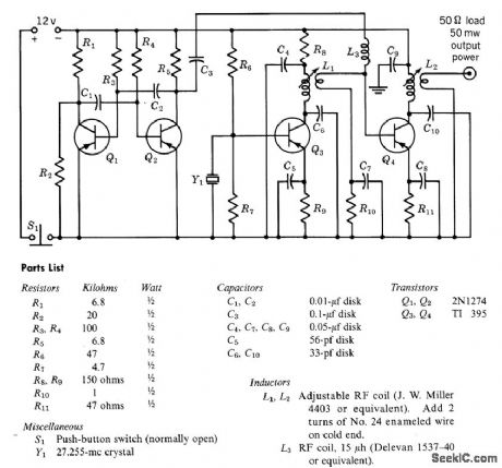
Free-running multivibrator keys power amplifier Q4 at audio role. Range is about 1 mile C6 tunes collector of oscillator to crystal frequency.-Texas lnstruments Inc., Transistor Circuit Design, McGraw-Hill, N.Y., 1963, p 361. (View)
View full Circuit Diagram | Comments | Reading(1101)
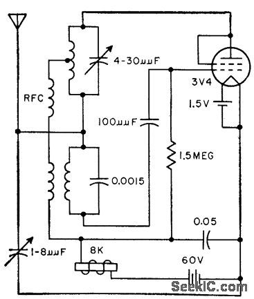
735_MC_CRYSTAL_CONTROLLED_TUNNEL_DIODE_TRANSMITTER
Published:2009/7/22 21:04:00 Author:Jessie
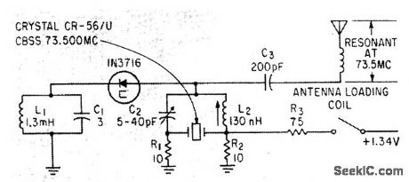
Self-modulated low-power oscillator for remote-controlled toys, trains, and garage doors can also be voice-modulated. Range is about 200 yards, and battery drain is 18 ma.-E. Gottlieb and J.Giorgis, Tunnel Diodes-Using Them as Sinusoidal Generators, Electronics, 36:24, p 36-42. (View)
View full Circuit Diagram | Comments | Reading(1127)
LINE_CURRENT_IV_CONTROL_RECEIVER
Published:2009/7/22 21:03:00 Author:Jessie
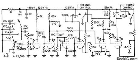
Can be considered as two separate receivers, one detecting unmodulated power-line carrier for channel selection, the other detecting hoth modulated and unmodulated carriers for sound-muting relay. Four individually tuned frequencies (52.5, 57.5, 67.5, und 73.5 kc) ate selectable by switching additional capacitors across that for highest frequency.-J. R. Banker and C. H. Wood, Jr., Line Current Controls Remote Tv Receiver, Electronics, 31:33, p 68-69. (View)
View full Circuit Diagram | Comments | Reading(1099)
EIGHT_COMMAND_RECEIVER
Published:2009/7/22 20:53:00 Author:Jessie
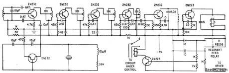
Ttransistorized superheterodyne with crystal-controlled local oscillator energizes eight-reed relay, with each reed activating own transistor switch. Reeds are tuned to different frequencies between 250 and 500 cps.-R. A Baker, Rcdio-Controlled Tank for Realistic Combat Training, Electronics, 33:45, p 55-57, (View)
View full Circuit Diagram | Comments | Reading(1191)
DRONE_RECEIVER
Published:2009/7/22 20:52:00 Author:Jessie
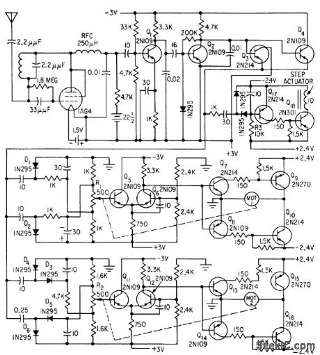
Signal from ground transmitter is received by logarithmic mode (self-quenching) superregenerative receiver. Clipper Q2 limits signal to constant level. Combinations of prr and pulse symmetry alter positions of rudder and elevator motors. Engine speed, transmitted by momentarily interrupted modulation, acts on Q17.Q18.-G. B. Herzog, Transistors Simplify Control of Target Drone, Electronics, 32:18, p 52-54. (View)
View full Circuit Diagram | Comments | Reading(2164)
460_MC_F_M_COMMAND_RECEIVER
Published:2009/7/22 20:48:00 Author:Jessie
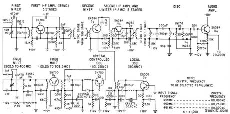
Transistorized double-conversion f-m superhet, tunable by crystal substitution in 457-462-Mc band, has 6-microvolt sensitivity for 20 db of noise quieting. Camera start and timing pulses are amplitude-modulated onto 3.5 and 12-kc carriers. After signal is detected, subcarriers are separated and pulses ore re constituted by decoder. Start pulses operate camera relays, and timing pulses lash neon lamps.-F. M. Gardner and L. R. Hawn, Camera Control System for Rocket Sled Tests, Electronics, 33:14, p 63-65. (View)
View full Circuit Diagram | Comments | Reading(1129)
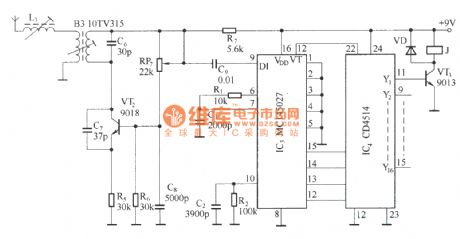
Multi-channel remote control circuit diagram
Published:2011/4/8 3:03:00 Author:Rebekka | Keyword: multi-channel remote control
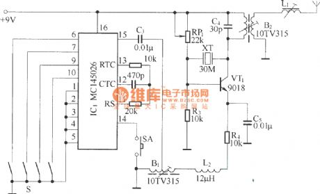
Multi-channel remote control transmitter circuit diagram(MC145026 is a digital encoder):
Multi-channel remote control receiver circuit diagramCD4514BCD is a 4-16 line decoder):
(View)
View full Circuit Diagram | Comments | Reading(4059)
COMMUTATOR_SYNCHRONIZER
Published:2009/7/23 21:36:00 Author:Jessie
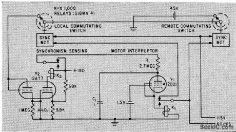
Automatic synchronizing circuit consists of motor interrupter and synchronism-sensing circuit. Commutator drive motor at control transmitter is interrupted until it syncs with commutator drive motor in robot that performs jobs in dangerous radioactive areas. Each interrupt makes motor drop bock 90°, so that only up to three interruptions are required to achieve synchronism.-D. A. Campbell, Multiplex Circuits for Control of a Robot, Electronics, 33;4, p 46-48. (View)
View full Circuit Diagram | Comments | Reading(1324)
EIGHT_COMMAND_TRANSMITTER
Published:2009/7/23 21:43:00 Author:Jessie
Two lone channels can be transmitted simultaneously. Operates at 27 Mc with 0.25.w output, for controlling model tank-R. A. Baker, Radio-Controlled Tank for Realistic Combat Training, Electronics, 33:45, p 55-57. (View)
View full Circuit Diagram | Comments | Reading(1120)
WIDEBAND_F_M_RADIO_CONTROL_LINK
Published:2009/7/23 21:39:00 Author:Jessie
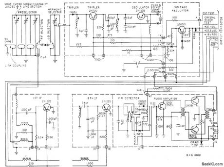
Covers 406 to 549 Mc. Used in missiles and missile-target aircraft to receive up to 20 tone channels and provide demodulated audio output to decoding equipment. Second through seventh i-f channels are essentially same as eighth.-T. L. Fischer, Wideband F.M Receiver for Remote Aircraft Control, Electronics, 33:40, p 85-87. (View)
View full Circuit Diagram | Comments | Reading(1822)
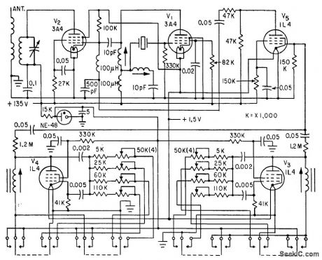
FRANKLIN_SUPERREGENERATIVE_RECEIVER
Published:2009/7/23 21:42:00 Author:Jessie
Has low sensitivity to impulse noise, wide dynamic range, high gain, and flexibility, since quench oscillator components are at r-f potential and feedback adjustments more easily made. Oscillates at 27 Mc as modified Hartley with interelectrode capacitances tuned by L1, and also oscillates at 25-kc quench frequency. Provides large decrease in plate current when signal arrives.-S. J.Neshyba and F. E. Brooks, Jr., Stable Receiving Circuits for Remote Control, Electronics, 31:31, p 74-76. (View)
View full Circuit Diagram | Comments | Reading(1171)
| Pages:10/34 1234567891011121314151617181920Under 20 |
Circuit Categories
power supply circuit
Amplifier Circuit
Basic Circuit
LED and Light Circuit
Sensor Circuit
Signal Processing
Electrical Equipment Circuit
Control Circuit
Remote Control Circuit
A/D-D/A Converter Circuit
Audio Circuit
Measuring and Test Circuit
Communication Circuit
Computer-Related Circuit
555 Circuit
Automotive Circuit
Repairing Circuit