
Remote Control Circuit
Index 8
The fifteen-channel wireless anti-theft alarm system
Published:2011/8/1 22:08:00 Author:TaoXi | Keyword: Fifteen-channel, wireless, anti-theft alarm
(a) is the coding launch circuit. There is the digital coding circuit VD5026 in the FDD5 component, and you can preset the code. When you are using this circuit, you just need to connect the component's power, the launch component will automatically output signals. (b) is the remote control receiving decoder circuit. The JDD5 also has the decoding circuit VD5027.
(View)
View full Circuit Diagram | Comments | Reading(1421)
The twelve-channel wireless remote control circuit TH9738
Published:2011/8/1 22:08:00 Author:TaoXi | Keyword: Twelve-channel, wireless remote control
The key components datathat will be used in this artical:
TH9738 CD4514 78L05 9014
(View)
View full Circuit Diagram | Comments | Reading(969)
Cooking Timer Circuit
Published:2011/7/20 3:17:00 Author:Joyce | Keyword: Cooking , Timer
Cooking timer circuit is as shown in the figure:
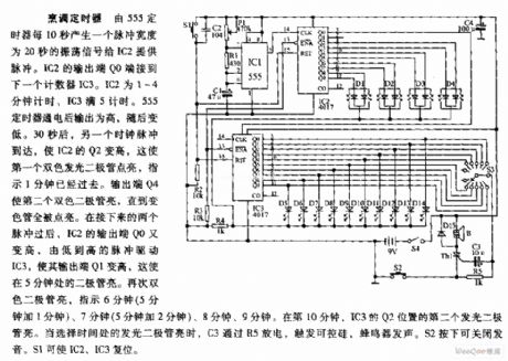
Cooking Timer: Oscillating signal of 20 seconds pulsing width is produced by timer 555 every 10 seconds to provide pulse for IC2. The output end Q0 of IC2 is connected with the next timer IC3. The timing time of IC2 is 1~4 minutes and that of IC3 is 5 minutes. After the timer 555 is provided with power, its output is high, but becomes low afterwards. 30 seconds later, the arrival of another clock pulse will increase the value of Q2 of IC2, which indicates that 1 minute is gone by. The output end Q4 will lighten the first two-tone diode till the whole color tube is lightened. After the next two pulses, output end Q0 of IC2 becomes high again. The pulse changing from low to high will drive IC3 and increase its output end Q1. This will lighten the diode which is set at the point of 5 minutes. (View)
View full Circuit Diagram | Comments | Reading(1399)
Water Quality Detector Circuit
Published:2011/7/20 3:18:00 Author:Joyce | Keyword: Water Quality , Detector
The water quality circuit is as shown in the figure:
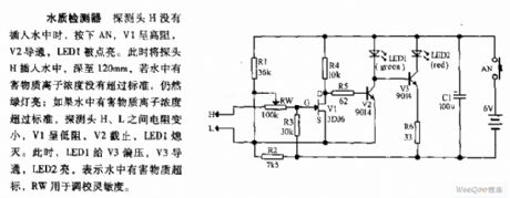
Water Quality Detector Circuit: When the detecting head has not been inserted into the water, if one presses AN, V1 will display that the impedance is high, V2 will break over and LED1 will be lightened. Once inserting the detecting head into 120mm deep under the water, the green light will still be on if the concentration of ions of harmful substance has not exceeded the standard. If not so, the impedance between detecting head H and L will become smaller. Then V1 will show low impedance, V2 will cut off, and LED1 will go out. At this time, LED1 will offer bias voltage to V3 which will break over afterwards. And LED2 will be lightened, indicating harmful substance in the water has exceeded the standard. RW is used to adjust the sensitivity. (View)
View full Circuit Diagram | Comments | Reading(1753)
High-precision Delay Timer Circuit
Published:2011/7/21 21:56:00 Author:Joyce | Keyword: High-precision Delay, Timer
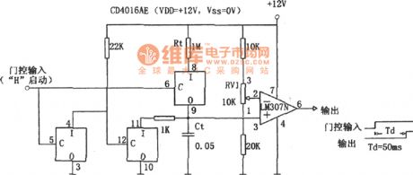
As shown in the figure is a high-precision delay timer circuit. In the figure, Rt, Ct are timing elements, with timing time T being RtCt (s). Changing the values of Rt, Ct can adjust the time of timing, but by doing so, the stability will get worse, so, usually it is achieved by adjusting the comparative level of the comparator, that is to say, by adjusting RV1 in the figure.
This circuit can improve the precision of timing. It requires comparator, capacitance, resistance of stable performance and switch mode with no disorder voltage, low on resistance and high cut-off resistance. (View)
View full Circuit Diagram | Comments | Reading(1469)
The Circuit Diagram of One-hour Timing Circuit Using LM122
Published:2011/8/8 11:24:00 Author:Felicity | Keyword: Timing Circuit
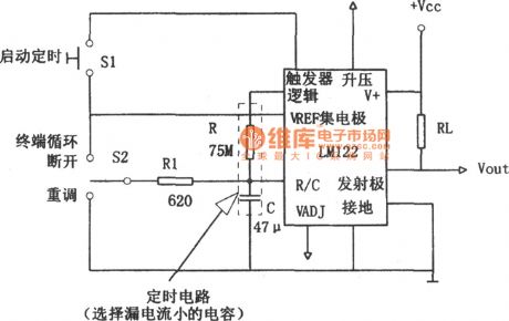
In this figure S1 can start timing and when the timer starts, turning this switch has no effect.S2 is the “OFF” switch in the middle and turning this switch can make the timer complete the procedure: charging-open circuit-discharging. Because of charging stopped halfway, the charging position would return to the work state of the timer’s output circuit. And when C discharges, the voltage of R/C is zero and the charging position awaits the start signal of S1. (View)
View full Circuit Diagram | Comments | Reading(2005)
Timer circuit using the monostabillity free-send device
Published:2011/7/20 6:22:00 Author:Fiona | Keyword: the monostabillity free-send device, Timer
This circuit's characteristic is that input end has anti-interference protection measures to prevent malfunction caused by interference signals.In addition,the time process ends before the switch S is off,it increases reliability.
(View)
View full Circuit Diagram | Comments | Reading(1011)
99_s_PROGRAMMABLE
Published:2009/7/13 4:10:00 Author:May
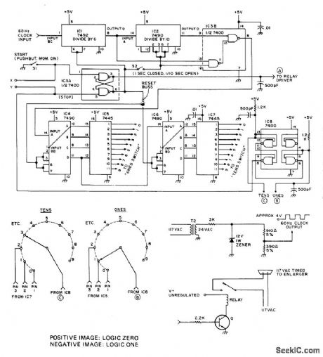
Line-frequency-based precision interval timer was developed for use with repeaters or photographic enlargers. Circuit is accurate to within 1/60 s. Two 10-position switches are set to desired interval. Connection to AC line gives 4-V square wave for 60-Hz clock input. Transistor type used as relay driver is not critical.-G.R. Allen, Dependable Timer, 73 Magazine, July 1976, p 84-87. (View)
View full Circuit Diagram | Comments | Reading(1635)
HIGH_VOLTAGE_PROBE
Published:2009/7/17 1:56:00 Author:Jessie
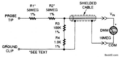
This high-voltage probe allows your DMM to take high-voltage measurements to 10,000 V peak, and acts as a high-impedance (100-MΩ) probe for high-impedance circuit testing. The probe was designed to plug into a standard 10-MΩ input DMM. If your DMM has a different input, you can change R3 and R4 to suit it. The ratio of R1 + R2 + R3 + R4 should be exactly 1000 to 1; thus, a 10.00-V in-put will read 10.00 mV on your DMM. Keep in mind that the impedance of your DMM is in parallel with R3/R4 when you calculate new values. (View)
View full Circuit Diagram | Comments | Reading(4163)
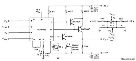
ADJUSTABLE_D_C_LEVEL_SHIFTER
Published:2009/7/17 1:53:00 Author:Jessie
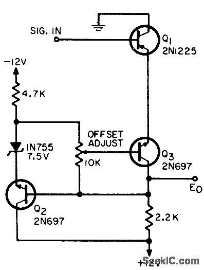
Shills d-c level of signal accurately and continuously without affecting gain, from +4 V to +z V d-c center-voltage output. Input ac signal varies 2 v about +4 v d-c. Other offset voltages can also be obtained.-H Anway Continuously Adjustable DC Level Shifter, EEE, 12:10, p 59. (View)
View full Circuit Diagram | Comments | Reading(1149)
SIMPLE_REMOTE_CONTROL
Published:2009/7/17 4:10:00 Author:Jessie
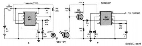
Here is a remote-control transmitter and receiver. The theory of the circuit's operation is very simple. The transmitter (Fig. A) generates IR light pulses at a frequency of 320-Hz (set in part by R2). The pulses arrive at the collector of the phototransistor and are amplified by the 2N2222 transistor. An NE567, IC2, is tuned to 320-Hz (by R6), so if pulses of any other frequency arrive at the phototransistor, the NE567's output will remain high. When the 320 Hz signal enters the phototransistor, the NE567 recognizes this frequency and pulls its output low. If you wish to change the NE567's operating frequency, you will have to adjust R2 and R6 to the same value. Keep in mind that the NE567 will work between 100 Hz and 1 kHz. You can also add more resistors (for more frequencies) instead of R2, and more NE567s tuned at the desired frequencies in order to make a multichannel remote control system. (View)
View full Circuit Diagram | Comments | Reading(7251)
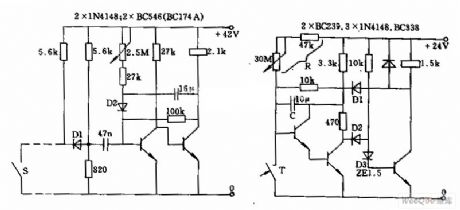
The infrared temperature control circuit composed of heat releasing electric sensors
Published:2011/7/20 1:18:00 Author:Borg | Keyword: infrared temperature control circuit, heat releasing electric sensors
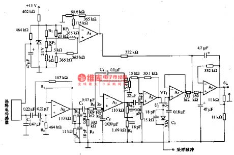
The temperature compensation circuit consists of RT and A1. A6 composes the addition circuit, A6 adds up the outputs of the temperature compensation circuit and the synchronous rectifier circuit, whose output is the corresponding voltage of the object temperature under test. In figure (b) is the amplifier part, detection part, timing part and relay drive part and so on of the circuit. The power supply of the circuit is DC 6-8V, the working current is 70mA, the standby current is 2mA, the maximum range of the sensor is 5m, the time is about 5-22S.
(View)
View full Circuit Diagram | Comments | Reading(2026)
Discrete_level_shifting_circuit
Published:2009/7/21 2:41:00 Author:Jessie
Discrete level-shifting circuit (courtesy Motorola Semiconductor Products Inc.). (View)
View full Circuit Diagram | Comments | Reading(1038)
TC9149P/TC9150F (Video recorder and TV set) infrared remote control receiving circuit
Published:2011/7/27 19:08:00 Author:TaoXi | Keyword: Video recorder, TV set, infrared, remote control, receiving circuit
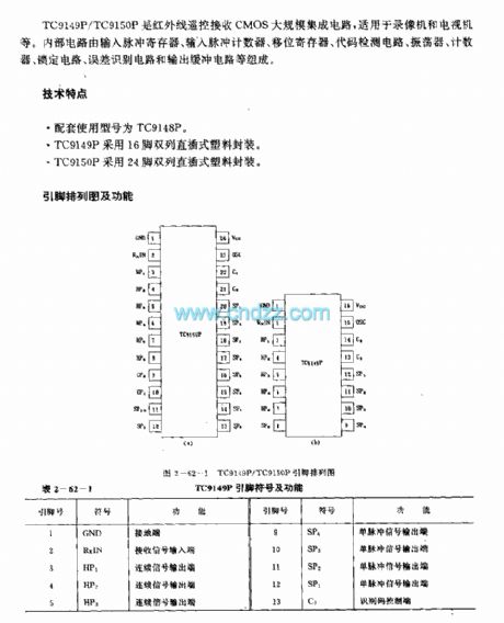
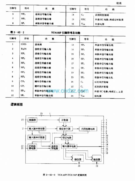
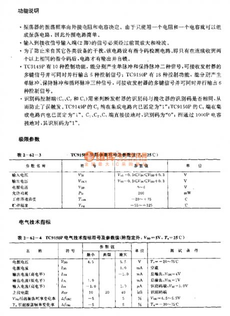
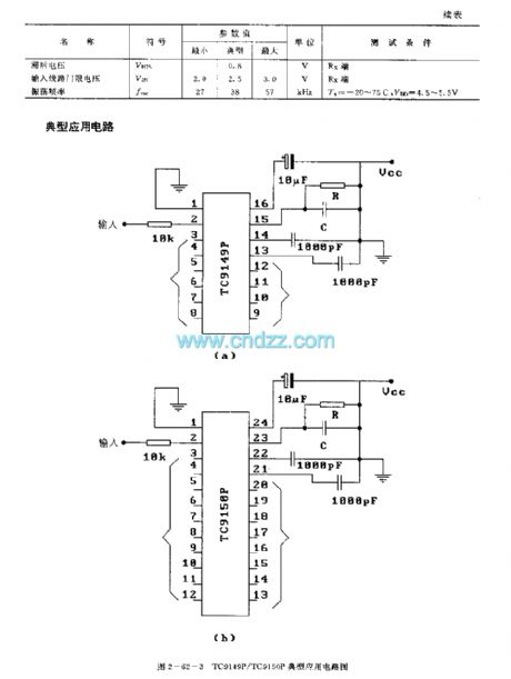
The TC9149P/TC9150F is designed as the infrared remote control receiving CMOS large-scale circuit that can be used in the video recorder and TV set applications. The internal circuit is composed of the input pulse register, the input pulse counter, the shift register, the code detection circuit, the oscillator, the counter, the locking circuit, the error identification circuit and the output buffer circuit.
Features
The matching model is TC9148P.The TC9149P uses the 16-pin dual-row DIP plastic package.The TC9150P uses the 24-pin dual-row DIP plastic package.
Function declaration
The oscillation frequency of the oscillator is decided by the external resistance and capacitance.The signal adds to the signal receiving input port pin-2 after it is amplified and detected by the circuit.
(View)
View full Circuit Diagram | Comments | Reading(2221)
TA7657P (electronic toys) radio remote control receiving circuit
Published:2011/7/27 3:59:00 Author:TaoXi | Keyword: electronic toys, radio, remote control, receiving circuit
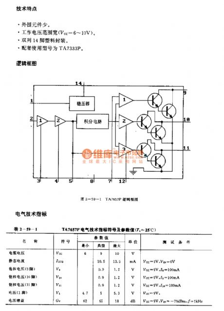
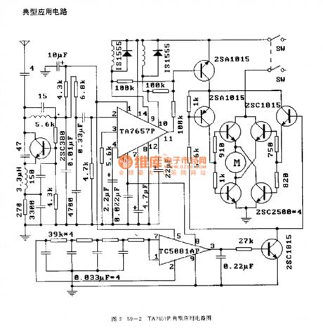
The TA7657P is designed as one kind of radio remote control receiving circuit that can be used in the electronic toys. The internal circuit is composed of the amplifier, the voltage stabilizer, the integral circuit, the comparator and the driver.
Features
Little external components.Wide operating voltage range (Vcc=6-10V).Dual-row 14-pin plastic package.The matching model is TA7333P.
(View)
View full Circuit Diagram | Comments | Reading(2505)
T6A2800 (TV) infrared remote control receiving circuit
Published:2011/7/27 4:15:00 Author:TaoXi | Keyword: TV, infrared, remote control, receiving circuit
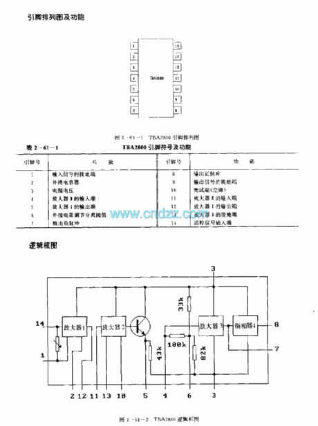
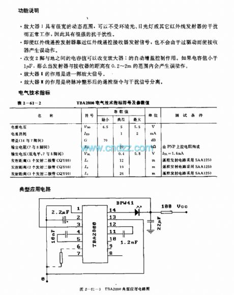
The T6A2800 is designed as the infrared remote control receiving bipolar type circuit that can be used in TV application. The internal circuit is composed of the gain control amplifier I, amplifier II, the pulse separation amplifier III and the inverter. The matching models are SAA1250 or IRT1250. It is in the 14-pin dual-row DIP plastic package.
Function declaration
The amplifier I has the wide dynamic range, it will not interfere by the environment light, the fluorescent lamp or other infrared transmitters.
Even if the infrared remote control transmitter closes to the infrared remote control receiver transmitter signal, the receiver will not produce the false action because of the overdrive.
(View)
View full Circuit Diagram | Comments | Reading(1599)
TA8141S (TV) infrared remote control receiving circuit
Published:2011/7/27 4:29:00 Author:TaoXi | Keyword: TV, infrared, remote control, receiving circuit
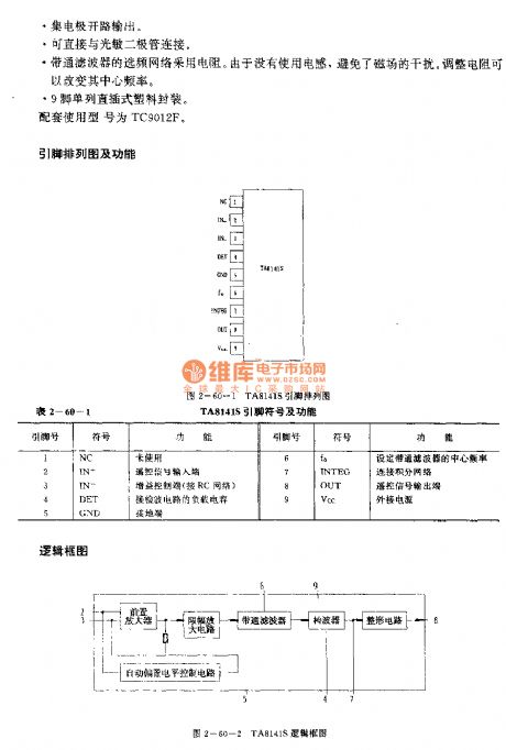
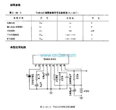
The TA8141S is designed as one kind of infrared remote control receiving bipolar type circuit that can be used in the TV application. The internal circuit is composed of the preamplifier single circuit, the ABLC circuit, the amplitude limiting amplifier circuit, the bandpass filter, the wave detector and the shaping circuit.
Features
Low current consumption. When the power supply voltage is 5V, the operating current is 2mA.This circuit has the band-pass filter, and you do not need to adjust the band-pass filter (BPF).The collector electrode is in the open-circuit output state.It can be connected with the photodiode directly.The frequency-selective network of the band-pass filter uses the resistance.9-pin single row DIP plastic package.The matching model is TC9012F.
(View)
View full Circuit Diagram | Comments | Reading(1186)
TA7344P general remote control receiving preamplifier circuit
Published:2011/7/27 19:11:00 Author:TaoXi | Keyword: general, remote control, receiving, preamplifier circuit
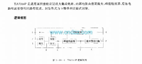
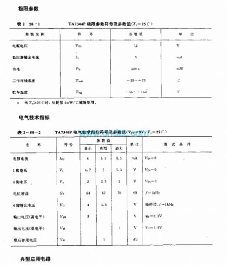
The TA7344P is designed as the general remote control receiving preamplifier circuit. The internal circuit is composed of the preamplifier circuit, the peak value detection circuit, the voltage stabilization circuit, the waveform plastic loop. It is in the 9-pin single row DIP package.
(View)
View full Circuit Diagram | Comments | Reading(877)
KAA3009/SAA3049 infrared remote control decoder circuit
Published:2011/7/27 21:17:00 Author:TaoXi | Keyword: infrared, remote control, decoder circuit
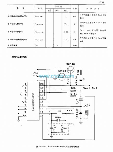
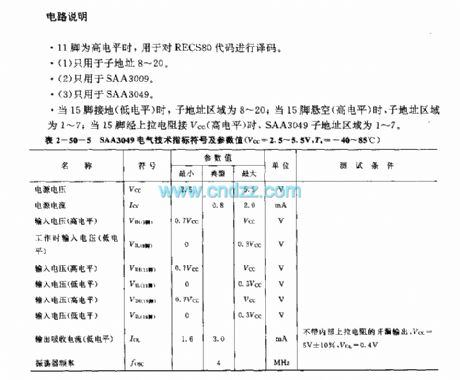
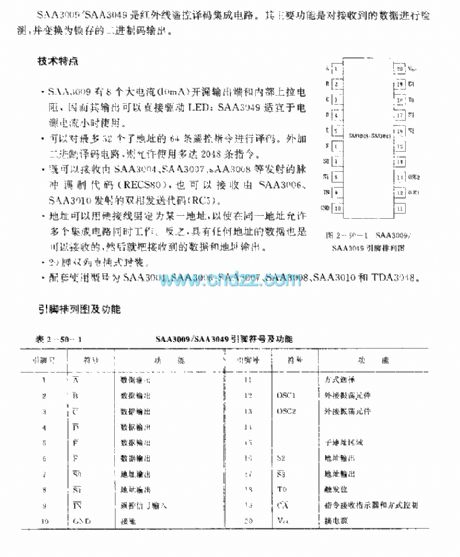
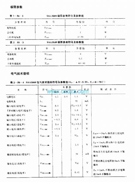
The SAA3009/SAA3049 is designed as the infrared remote control decoder circuit. The main function of this device is to detect the received data and change the data into the binary code.
Features
The SAA3009 has eight large current (10mA) open-drain output port and the internal pull-up resistance, because the output of it can drive the LED directly, the SAA3049 can be used in the small power current condition.
It can decode the 64 remote control instructions of 52 addresses.
It can receive the pulse modulation codes of SAA3004, SAA3007 and SAA3008, also it can receive the diphase sending codes of SAA3006, SAA3010.
(View)
View full Circuit Diagram | Comments | Reading(2101)
LJC2200 (air conditioner, electric fan, radio, television and toy) infrared, ultrasonic and radio remote control receiving circuit
Published:2011/7/27 22:03:00 Author:TaoXi | Keyword: air conditioner, electric fan, radio, television , toy, infrared, ultrasonic, radio, remote control, receiving circuit
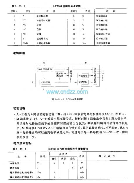
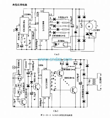
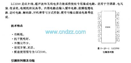
The LC2200 is designed as the infrared, ultrasonic and radio remote control receiving circuit that can be used in the air conditioner, electric fan, radio, television and toy applications. The internal circuit is composed of the input buffer circuit, the fault detection circuit, the timing circuit, the decoder, the boot-reset circuit, the mode control circuit, the latch and output driver circuit.
Features
Low power consumption.Good anti-interference performance.Little external components.Easy to use.The matching model is LC2190.
(View)
View full Circuit Diagram | Comments | Reading(1159)
| Pages:8/34 1234567891011121314151617181920Under 20 |
Circuit Categories
power supply circuit
Amplifier Circuit
Basic Circuit
LED and Light Circuit
Sensor Circuit
Signal Processing
Electrical Equipment Circuit
Control Circuit
Remote Control Circuit
A/D-D/A Converter Circuit
Audio Circuit
Measuring and Test Circuit
Communication Circuit
Computer-Related Circuit
555 Circuit
Automotive Circuit
Repairing Circuit