
Remote Control Circuit
Index
16-channel remote control circuit schematic (T998C)
Published:2013/1/29 2:33:00 Author:Ecco | Keyword: 16-channel, remote control
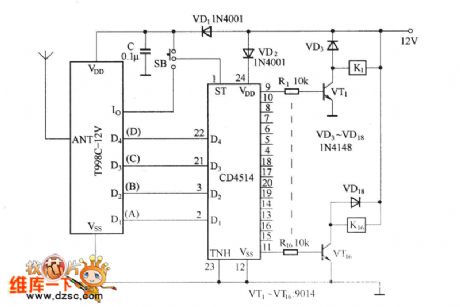
The circuit is not only used for the latch output, but also for non - latched output, SB is control switch. When SB and VDD are turned on, it is in the latch output state, then the sixteen output ends are out control of Io output state; when SB and Io output ends are connected, it is in non- latched output state, then the output states are under control of Io output state.
(View)
View full Circuit Diagram | Comments | Reading(11228)
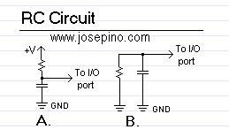
RC circuit
Published:2013/1/17 21:05:00 Author:muriel | Keyword: RC circuit
View full Circuit Diagram | Comments | Reading(3365)
Ultrasonic liquid level remote control and indicator circuit
Published:2012/10/26 21:10:00 Author:Ecco | Keyword: Ultrasonic , liquid level , remote control, indicator
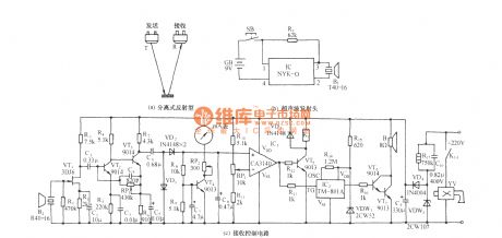
As shown in the figure, the circuit includes the ultrasonic transmitter and ultrasonic receiving and control circuir. It uses the characteristic that ultrasonic has a larger propagation loss in the air, and the propagation characteristics in different media such as gases, liquids. It use isolation-emitting ultrasonic technology shown in figure a to measure distance, liquid or material.
(View)
View full Circuit Diagram | Comments | Reading(4801)
Remote control Encoder M145026B-1
Published:2012/9/12 21:03:00 Author:Ecco | Keyword: Remote control Encoder
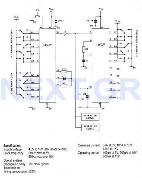
This encoder can generate up to 19,683 codes from 9 address lines by detecting 1,0, or open circuit. To initiate the transmit sequence, pin 14 should be pulsed low. The encoder will now output on pin 15 a data stream representing the condition on each of the address/data pins in turn and then repeat the operation, so that two complete identical words are transmitted. If pin 14 is held low, the output will be continuous, otherwise two identical words are output for each pulse on pin 14. A 1 is transmitted as two long pulses, a 0 as two short pulses, and an open circuit as a long pulse followed by a short pulse.
Source: NEXT.GR (View)
View full Circuit Diagram | Comments | Reading(3512)
TV/VCR Infrared Remote Booster
Published:2012/9/10 20:37:00 Author:Ecco | Keyword: TV/VCR , Infrared , Remote Booster
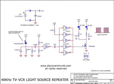
This circuit will boost the signal from any infrared TV or VCR remote, extending the range by a factor of 3X.
Source: discovercircuits (View)
View full Circuit Diagram | Comments | Reading(4505)
Sonic remote control light switch circuit (1 )
Published:2012/9/4 22:08:00 Author:Ecco | Keyword: Sonic , remote control, light switch
It uses clap as a remote command, once pat your palms, the lights will be lit; pat your palms again, the lights will be extinguished. The inverter I ~ IV uses a piece of six NOT gate CD4096 digital integrated circuit; B uses FT- 27, HTD27A -1 ordinary piezoelectric ceramic.
(View)
View full Circuit Diagram | Comments | Reading(3797)
Sonic remote control light switch circuit (2)
Published:2012/9/4 22:11:00 Author:Ecco | Keyword: Sonic , remote control , light switch
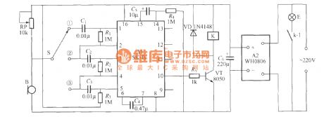
As shown in figure, it is a sonic remote control light switch with SK-Ⅳ voice-control ASIC, it has strong anti-interference ability, reliable performance. K uses small electromagnetic relay with 6V operating voltage, such as JZC -22F, DC6V ; B is available to use CRZ2-113F electret condenser microphone.
(View)
View full Circuit Diagram | Comments | Reading(4108)
Remote control starting up and shutdown circuit with installing VCD machine
Published:2012/8/27 22:57:00 Author:Ecco | Keyword: Remote control , starting up, shutdown , installing VCD machine
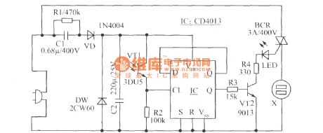
CD machine has a lot of remote control functions, but usually it does not have remote control starting up and shutdown function, and its power line is shorter. As shown in the figure, it is the remote control starting up and shutdown circuit which is added on CD machine.
Components selection; IC selects CMOS double D triggers CD4013. VT1 selects 3DU5 phototransistor. VT2 choose 9,013 NPN silicon tube, β>100. BCR selects 3A400V TRIAC such as TLC226 and so on. LED selects 5mm red light-emitting diode with any models. X selects 220V,10A flat dark socket. The remaining components are shown in the figure.
(View)
View full Circuit Diagram | Comments | Reading(3931)
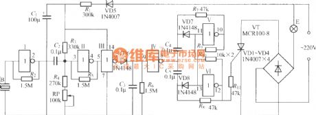
Infrared remote control dimming chandeliers circuit diagram
Published:2012/7/23 3:17:00 Author:Ecco | Keyword: Infrared , remote control , dimming chandeliers
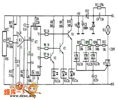
This infrared remote control dimming chandelierdescribed can use the remote controllerof household appliances ( such as TV, DVD player , VCR , etc. ) to control opening, turning off and dimming (3 files of strong, medium and weak light)of the lights.The working principle:The infrared remote control dimming chandelier circuitconsists of power circuit , IR receiver amplifier circuit and the dimming control circuit, and it isshown as the chart.
(View)
View full Circuit Diagram | Comments | Reading(4288)
Delay circuit with operational amplifier
Published:2011/8/29 1:51:00 Author:Jessie | Keyword: Delay circuit , operational amplifier
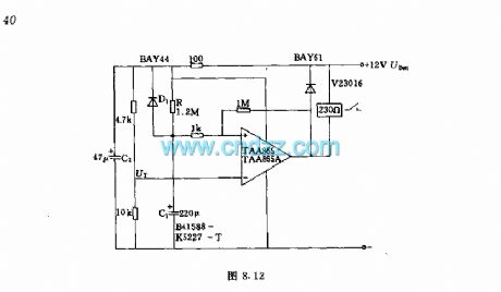
After plug-in power, the relay on the output terminal closes immediately, and release safter the prescribed delay time.Technical characteristicsWorking voltage: 12V + 20%Delay time: about 260sRepeat preparation time: about 12s
(View)
View full Circuit Diagram | Comments | Reading(3189)
The static switch with integrated trigger TDAl024
Published:2011/8/28 22:24:00 Author:Jessie | Keyword: static switch , integrated trigger
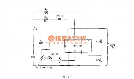
Thecircuitof integrated flip-flop TDA1024 will be connected afterswitch S closed. Whenever thepower gridvoltage is zero, it willproducea triggering pulse, and make the thyristor conduction, load current flow through the RL. When switch S is off, there is no current in load. In order to protect the Triac, it should be connected a varistor at both ends in parallel. The maximum power output of the circuit is 1400W, for example, if it uses thyristor BT139, the output power is up to 2000W; if it uses BTW41, the output power can be up to 5000W. (View)
View full Circuit Diagram | Comments | Reading(2972)
U9D6121G一001(TV and video)infrared remote control launch circuit
Published:2011/8/29 2:09:00 Author:Jessie | Keyword: infrared, remote control
μPD6121G is infrared remote control launch circuit, which is suitable for TV and video, etc. The Internal circuit is composedof the oscillating circuit, points frequency device, clock produces circuit, keyboard input circuit, keyboard output circuit, control circuit, data registers, etc.
Technical characteristicsCMOS large scale integrated circuits.Power supply voltage, the range is 2.0~3.3V.Power consumption is small. When it is static, the current is less than 1μA.Supporting use with model CXK20106A.
20-pin dual in-line plastic package.
(View)
View full Circuit Diagram | Comments | Reading(2843)
Medication regularly remind decoder circuit with CD4541
Published:2011/8/30 2:15:00 Author:Jessie | Keyword: Medication, remind decoder
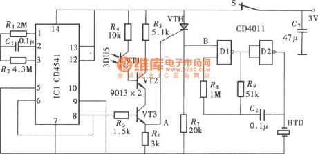
Medication regularly remind decoder is designed for those sicks who needs constantly medication. This reminder can be installed on family special medicine box, and it sets timer intervals according to the number of taking medicine everyday. When arrived at the scheduled time, reminder sounds. After openning medicine box, the sound stops and enters the nexttiming interval. This circuit is composedof the timer, remind audio generator and related control circuit. (View)
View full Circuit Diagram | Comments | Reading(4970)
UM3758 Infrared or ultrasonic remote-controlled transceiver amphibious circuit
Published:2011/8/30 21:32:00 Author:Jessie | Keyword: infrared, ultrasonic, remote-controlled
Technical characteristics:Using CMOS technology, low power consumption.Easy to link to other CMOS technology integrated circuits.Working voltage range is wide, and its value is 3 ~ 12 V.Containing RC clock oscillating circuit.Using mask choice to form series products.
(View)
View full Circuit Diagram | Comments | Reading(3217)
1X0773CE ( video ) infrared remote control transmitter circuit
Published:2011/8/31 1:41:00 Author:Jessie | Keyword: infrared, remote control transmitter
IX0773CE is infrared remote control transmitter circuit, whichissuitable for video, etc. The Internal circuit is composedof theoscillator, scanning, signal generator, data controller, modulation circuit, memory circuits, keyboard input circuit and coding circuit, etc. Technical features: it usesCMOS integrated circuit withlow power consumption; it has four inputs and eight outputs, which can form 4X8 keyboard matrix with 32 kinds of control functions; Oscillating circuit and 455kHz crystal cangenerate 38kHz timing signal; it can prevent multiple keys frompressing at same timeand causing misoperation; it uses 20-pin DIP.
(View)
View full Circuit Diagram | Comments | Reading(2841)
BIJ9148 ( general ) infrared remote control transmitter circuit
Published:2011/8/31 1:39:00 Author:Jessie | Keyword: general, infrared remote control, transmitter
BL9148 is general infrared remote control transmitter circuit. The Internal circuit is composedof theinput circuit, oscillating circuit, points frequency circuit, single clap/continuous command control circuit, the clock signal generator, instructions data control circuit and modulation circuit, etc. Technical features: it uses CMOS technology, power consumption is extremely low; Supply voltage range is 2.2 ~ 5.5 V; Peripheral components is less; It has external LC or ceramic filter; it uses 16-pin DIP.
(View)
View full Circuit Diagram | Comments | Reading(2966)
BUl301F ( TV and video) infrared remote control transmitter circuit
Published:2011/8/31 1:38:00 Author:Jessie | Keyword: infrared, remote control transmitter
BUl301F is theinfrared remote control transmit circuit. The Internal circuit is composedof theoscillator frequency device, drive, points, output drives, timing signal generates control circuit, shift register, read-only memory, keyboard scan signal input circuit and keypad scanning signal output circuit, etc. Technical features: CMOS technology, low power consumption; higher integration,less peripheral components;lowpower supply voltage;20-pin DIP.
(View)
View full Circuit Diagram | Comments | Reading(2794)
BA5101( Household appliances) infrared remote control coding circuit
Published:2011/8/31 1:32:00 Author:Jessie | Keyword: infrared, remote control coding
BA5101 is infrared remote controlcoding circuit, which is applicable to the household appliances such as electric fans. It supports the use of the BA5201.
(View)
View full Circuit Diagram | Comments | Reading(3101)
DIJ50462 (TV) infrared remote control transmit circuit
Published:2011/8/31 1:30:00 Author:Jessie | Keyword: infrared, remote control transmit
Technical characteristicsCMOS technology, low power consumption.Wide range power supply voltagein 2.2~5.5V.Only when people enter the button, oscillating circuit will produce oscillation, so power consumption is low.24-pin DIP.
OSCIN and OSCOUT sides externally connect LC or ceramic filters to generate 480KHZ and 455KHZ reference frequency, then it generates 40KHZ or 38KHz frequency carrier by internal fractional frequency. Emission control signal uses pulse position modulation (PPM), where 0 code is the negative pulse with the duty cycle in 1 / 4, 1 code is the negative pulse with duty cycle in 1 / 8. Negative pulse modulation is on the 38KHZ 40KHZ carrier.
(View)
View full Circuit Diagram | Comments | Reading(2790)
CX23040 ( TV and video)infrared remote control transmitter circuit
Published:2011/8/31 1:22:00 Author:Jessie | Keyword: infrared, remote control transmitter
CX23040 is infrared remote control transmit circuit, which is applicable to the TV and video, etc. It has eight inputs (pin 1 ~ 5, pin 25 ~ 27) and eight outputs (pin 9 ~ 13, pin 15 ~ 17), can form the 8x8 keyboard matrix.
(View)
View full Circuit Diagram | Comments | Reading(3098)
| Pages:1/34 1234567891011121314151617181920Under 20 |
Circuit Categories
power supply circuit
Amplifier Circuit
Basic Circuit
LED and Light Circuit
Sensor Circuit
Signal Processing
Electrical Equipment Circuit
Control Circuit
Remote Control Circuit
A/D-D/A Converter Circuit
Audio Circuit
Measuring and Test Circuit
Communication Circuit
Computer-Related Circuit
555 Circuit
Automotive Circuit
Repairing Circuit