
Index 294
Operation amplifier phase buffer circuit
Published:2011/4/14 1:04:00 Author:Jessie | Keyword: Operation amplifier, phase buffer
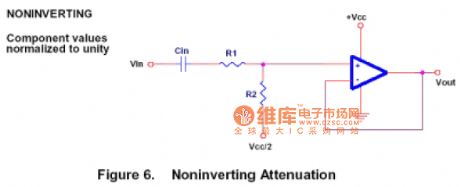
In figure, thein-phase attenuator can be used as a voltage attenuation and a in-phase buffer. (View)
View full Circuit Diagram | Comments | Reading(676)
Operation amplifier adder circuit
Published:2011/4/13 22:52:00 Author:Jessie | Keyword: Operation amplifier, adder

In figure, thereis an inverse adder,it is a basic audio mixer. But this circuit is rarely used in real audio mixer. Because it can approximate op-amp's work limit, actually we recommend increasing the supply voltage to improve dynamic range. In-phase addercan be realized, but is not recommended. Because the impedance of signal source will affect circuit's gain. (View)
View full Circuit Diagram | Comments | Reading(979)
Thyristor circuit with 100W, 700W and 1000W output power
Published:2011/4/13 2:16:00 Author:Nicole | Keyword: Thyristor, output power
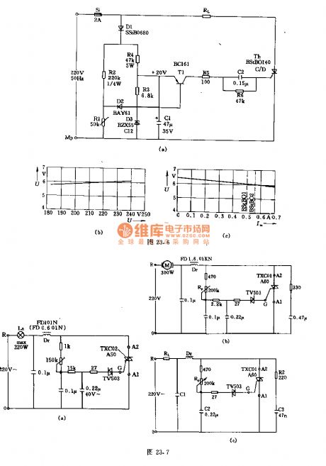
This is a non-contact power regulator circuit, the load is light La. To change 150kΩ potentiometer can achieve phase shift, and adding trigger voltage to bidirectional thyristor gate through bidirectional trigger, to control the conduction.
Main technical data: network voltage: 220±10%V; the adjustable range of output voltage: 10~230V; power: 100W, 700W, 1000W; bidirectional thyristor: TXC02-A60, TXC02-A6,; TXC03-A60; anti-interference capacitor: 0.22μF, 0.22μF, 0.27μF; the maximum environment temperature range: -15~+70℃, -15~+50℃, -15~+70℃.
The figures(b), (c) are the motor speed control practical circuit and illumination dimmer practical circuit, the maximum output power of later is 220W. (View)
View full Circuit Diagram | Comments | Reading(1403)
TRIAC AC steady voltage circuit
Published:2011/4/12 21:48:00 Author:Nicole | Keyword: TRIAC, AC steady voltage
View full Circuit Diagram | Comments | Reading(830)
Loss pulse alarm circuit
Published:2011/4/13 21:25:00 Author:Nicole | Keyword: Loss pulse, alarm
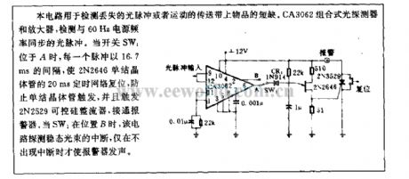
This circuit is used to test missing light pulse or the shortages of goods in sport transport tape. CA3062 combined photodetector and amplifier, it can test the light pulse which is synchronous with 60Hz power supply frequency. When switch SW1 is in A, each pulse is as 16.7ms interval to reset the 20ms timing network of 2N2646 unijunction transistor, to prevent unijunction transistor from triggering, and to trigger 2N2529 SCR turn on alertor. When SW1 is in B, this circuit interrupts detection steady light beam, the alertor alarms only in the case of without interruption. (View)
View full Circuit Diagram | Comments | Reading(799)
With 5 pilot lamp alarm circuit diagram
Published:2011/4/14 1:13:00 Author:Rebekka | Keyword: With 5 pilot lamp alarm
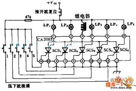
Intergrated circuit CA3083 has 5 NPN transistor. They are used in the same P-type substrate. You can use it as PNPN thyristor switch. Their public substrate is used as anticathode. If any button closed switch connected with controlled silicon, the anticathode load relay will be pulled in and the alarm will send warning signal. If any sensing switch on portal or window is colsed by the thief, the corresponding light will be lighten and point out where the thief is. Before the computer resets by cut off the power supply, the warning will keep sounding. In normal times, the circuit does not cost any power. The controlled silicon can support power for the circuit. (View)
View full Circuit Diagram | Comments | Reading(701)
Alternating voltage dual out-of-limit alarm circuit diagram
Published:2011/4/13 22:31:00 Author:Rebekka | Keyword: Alternating voltage dual out-of-limit alarm
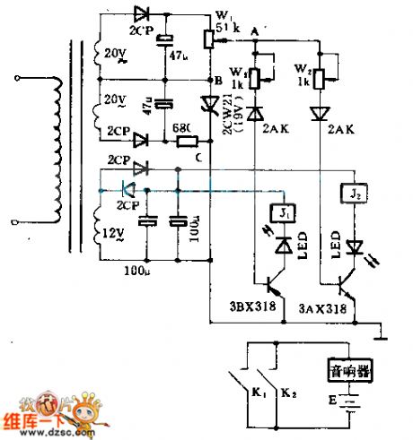
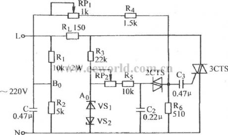
The alarm circuit can issue a directive when the power supply is higher or lower than the range. It can warn you to take appropriate measures. In the circuit, W2 and W3 seperate decide the starting value of up and down out-of-limit alarm. You can use high voltage device to adjust the circuit. (View)
View full Circuit Diagram | Comments | Reading(482)
Sounding photometer circuit diagram
Published:2011/4/13 22:12:00 Author:Rebekka | Keyword: Sounding photometer circuit
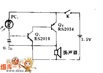
When dim light beat down on CdS photocell(Radio shack276-116), 8Ω speaker will produce a series of clic sound. As the light turn to stronger, the clic sound will disappear in the tone. The frequency of the sound will become higher as the light turn to stronger. The circuit can be used as teaching aid in classroom or sunrise clock report. (View)
View full Circuit Diagram | Comments | Reading(1075)
Composed of optical coupler electromagnetic valve drive circuit diagram
Published:2011/4/13 20:27:00 Author:Rebekka | Keyword: optical coupler , electromagnetic valve drive
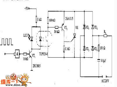
Composed of optical coupler electromagnetic valve drive circuit diagram is shown as above. TLP521-1 optical coupler eletric isolates the input and output. That is input TTL level circuit. The output uses 220V electromagnetic valve. The output can also use relay to control. (View)
View full Circuit Diagram | Comments | Reading(1453)
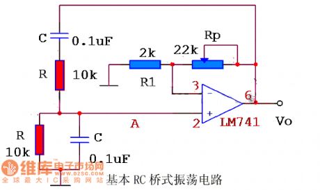
Basic RC bridge oscillating circuit diagram
Published:2011/4/13 3:02:00 Author:Jessie | Keyword: RC bridge, oscillating
View full Circuit Diagram | Comments | Reading(591)
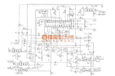
DZW75-48/50(50II) Startup control circuit
Published:2011/3/23 1:41:00 Author:muriel | Keyword: Startup control circuit, DZW75-48/50(50II)
View full Circuit Diagram | Comments | Reading(467)
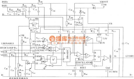
Boost/power factor correction control circuit of DMA
Published:2011/3/23 2:11:00 Author:muriel | Keyword: Boost/power factor , correction, control circuit, DMA, UC3854
View full Circuit Diagram | Comments | Reading(2002)
Composed of trigger and switch tube motor automatic speed governor circuit diagram
Published:2011/4/12 2:52:00 Author:Rebekka | Keyword: trigger and switch tube , motor automatic governor
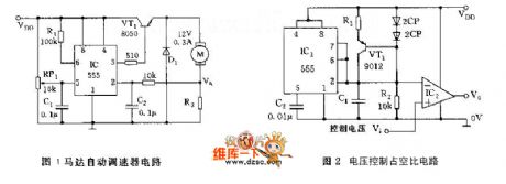
Motor automatic speed governor circuit is composed of 555 trigger and a switch. The sample circuit is composed of R7 and motor in series. When the operation runs within the specified speed, sample voltage VA<1/3VDD, 555 resets, VT1 is conducted, motor runs with power; When the speed overrun, VA>1/3VDD, the connection of R1 makes 555 reset and VT1 stop, the motor power-off, inertial rotation. When VA<1/3VDD, it makes 555 resets again, VT1 will be conducted and the motor works. It controlls the speed of motor all day long. RP1 is used for adjusting the control trigger level. (View)
View full Circuit Diagram | Comments | Reading(1236)
A kind of Temperature/frequency-Audio decoding temperature control circuit
Published:2011/3/23 1:57:00 Author:Jessie | Keyword: Temperature/frequency, Audio decoding, temperature control
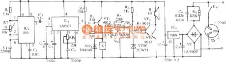
Circuit as shown, it is composed by many harmonic oscillator, audio decoder, relay control cooling equipment, twitter sound circuit andAC step-down rectifier circuit, etc. IC1 is a 555 time-based integrated circuit. It composes a self-motivating much harmonic oscillatorwith thermistor RT, R1, C1. When environment temperature changes, RT resistance of negative temperature coefficient (NTC)is changed too.
(View)
View full Circuit Diagram | Comments | Reading(774)
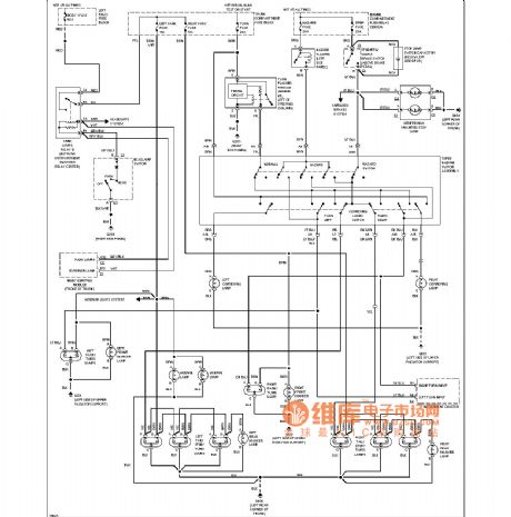
Cadillac external light circuit
Published:2011/4/13 2:00:00 Author:Jessie | Keyword: external light
View full Circuit Diagram | Comments | Reading(434)
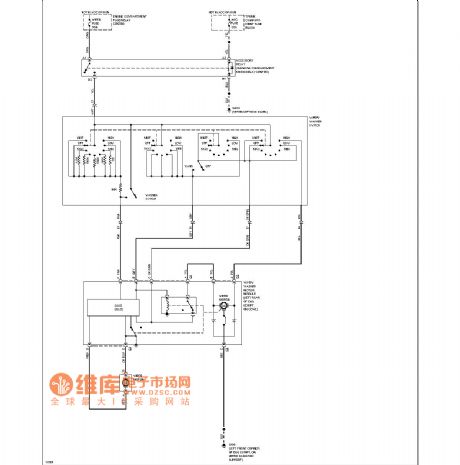
Cadillac wiper washers circuit
Published:2011/4/13 2:35:00 Author:Jessie | Keyword: wiper washers
View full Circuit Diagram | Comments | Reading(534)
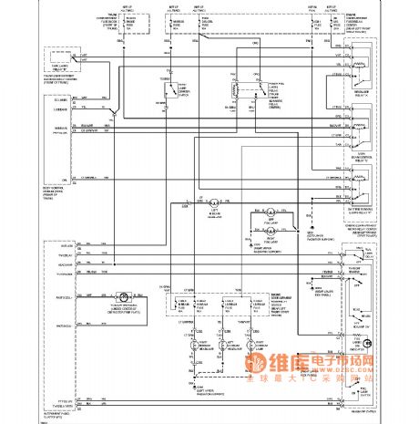
Cadillac headlamps circuit
Published:2011/4/13 1:57:00 Author:Jessie | Keyword: headlamp
View full Circuit Diagram | Comments | Reading(507)
Cadillac wind glass heating circuit
Published:2011/4/13 1:56:00 Author:Jessie | Keyword: wind glass heating
View full Circuit Diagram | Comments | Reading(442)
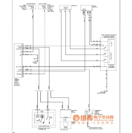
Cadillac electronic suspension circuit
Published:2011/4/13 2:02:00 Author:Jessie | Keyword: electronic suspension
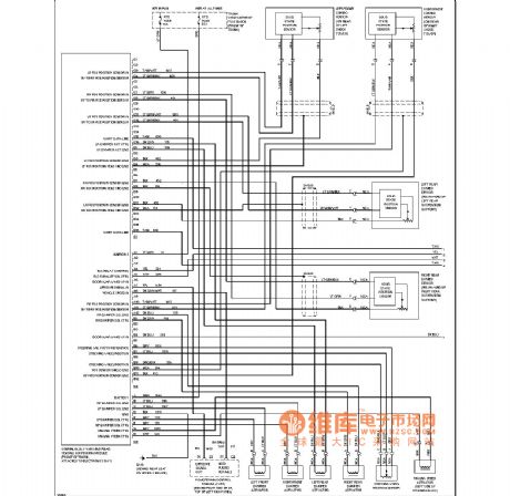
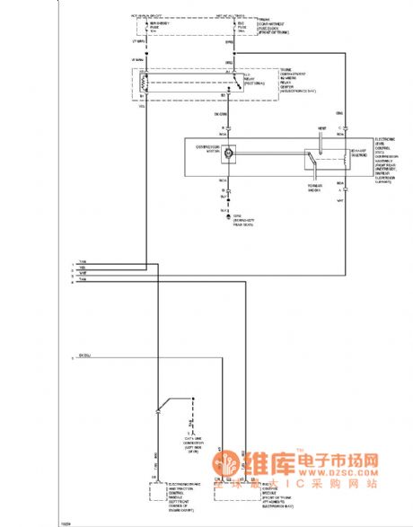
View full Circuit Diagram | Comments | Reading(514)
1000m single pipe oscillation FM transmitting circuit diagram
Published:2011/4/13 3:24:00 Author:Jessie | Keyword: 1000m single pipe, oscillation FM transmitting
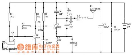
View full Circuit Diagram | Comments | Reading(518)
| Pages:294/312 At 20281282283284285286287288289290291292293294295296297298299300Under 20 |
Circuit Categories
power supply circuit
Amplifier Circuit
Basic Circuit
LED and Light Circuit
Sensor Circuit
Signal Processing
Electrical Equipment Circuit
Control Circuit
Remote Control Circuit
A/D-D/A Converter Circuit
Audio Circuit
Measuring and Test Circuit
Communication Circuit
Computer-Related Circuit
555 Circuit
Automotive Circuit
Repairing Circuit