
Index 282
Along trigger switch circuit composed of MIC5157
Published:2011/4/26 9:26:00 Author:TaoXi | Keyword: Along trigger switch
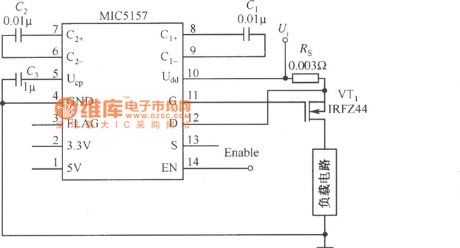
The along trigger switch circuit composed of MIC5157
(View)
View full Circuit Diagram | Comments | Reading(614)
SIPMOS transistor push pull control circuit
Published:2011/4/26 2:56:00 Author:May | Keyword: SIPMOS transistor, push pull control
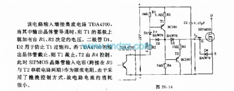
Input end of this circuit is connected integrated circuit TDA4700. When its output transistor turns on, base of T1 has voltage which is determined by R1, R2. Diode D1 and D2 is used to prevent the over saturation of T1. If output transistor of TDA4700 is cut off, T1 is cut off, T2 is controlled by R4, at this time, SIPMOS transistor input capacitor (crossover in the justified of R5 and T2) is as limiting resistor. The current consume of this circuit is very small because it adopts push pull control mode. (View)
View full Circuit Diagram | Comments | Reading(701)
Composed of YN5103IR/YN5203 encoder decoder matching infrared remote control application circuit diagram
Published:2011/4/21 10:12:00 Author:Rebekka | Keyword: infrared remote control application , encoder decoder matching
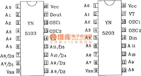
The matching use of YN5103 and decoder YN5203 can be widely used in automotive, building door security systems, home appliances and other aspects of multi-channel remote control.
YN5103/5203 shape pin map.
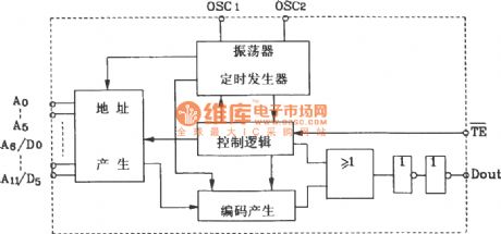
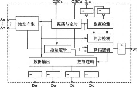
YN5103 internal block diagram.
YN5203 internal block diagram.
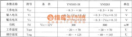
YN5103/YN5203 encoder / decoder, limits the working parameters:
General application YN5203 oscillation frequency of the decoder should be 2.5 to 8 times of YN5103-IR encoder oscillation frequency. Following table shows the three groups when paired with resistance.
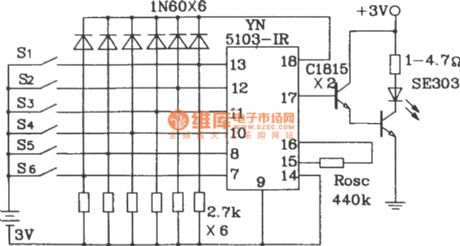
Infrared encoder composed of YN5103-IR.
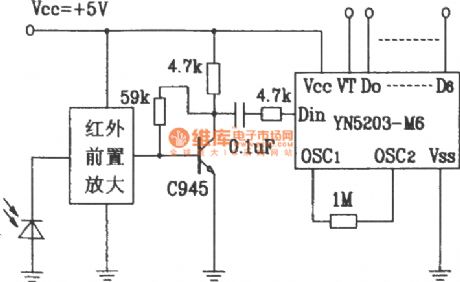
IR decoding circuit composed of YN5203-M6.
Oscillation resistor Rosc is YN5103: 440k, YN5203: 1M.
(View)
View full Circuit Diagram | Comments | Reading(1942)
Using BISS0001 infrared sensor automatic nighttime lighting control circuit diagram
Published:2011/4/19 22:19:00 Author:Rebekka | Keyword: Infrared sensor, Automatic nighttime lighting
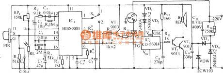
Circuit is shown in the figure, which is based on infrared sensing ASIC BISS0001 core composition, coupled with its external PIR pyroelectric infrared sensor and light control circuit. You can make one for the warehouse, shopping malls, corridors, other occasions, the automatic aisle lighting, lighting or security systems. (View)
View full Circuit Diagram | Comments | Reading(8912)
Touch-type anti-theft alarm circuit
Published:2011/4/24 9:38:00 Author:Christina | Keyword: Touch-type, anti-theft alarm
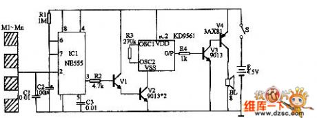
The touch-type anti-theft alarm can be used in wide range of applications such as the burglar alarm and the alarm of dangerous touch.etc. This alarm can automatic alarm and can automatic stop at the scheduled time.
As the figure showns. IC1 is the time-base integrated circuit NE555, the monostable trigger is composed of the IC1 and R1、C1、C2、C3. When no one touch the metal M1 to Mn, the circuit is stable, pin-3 of IC1 outputs the low-level signal, alarm circuit does not work. If anyone touch any piece of metal M1 to Mn, EMF of human body gives a negative pulse to pin-2 of IC1, the monostable circuit gets into the temporary-steady-state, pin-3 of IC1 become the high-level signal. This high-level signal makes the transistor V1 connect, so V2 also connect too, audio integrated circuits IC2 enters the working state. (View)
View full Circuit Diagram | Comments | Reading(989)
Power Disconnection Alarm Circuit
Published:2011/4/24 8:54:00 Author:Christina | Keyword: Power Disconnection, Alarm
The Power Disconnection Alarm Circuit is as shown:
(View)
View full Circuit Diagram | Comments | Reading(557)
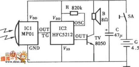
Ultrasonic remote control light switch circuit
Published:2011/4/24 22:21:00 Author:Nicole | Keyword: ultrasonic, remote control light, switch
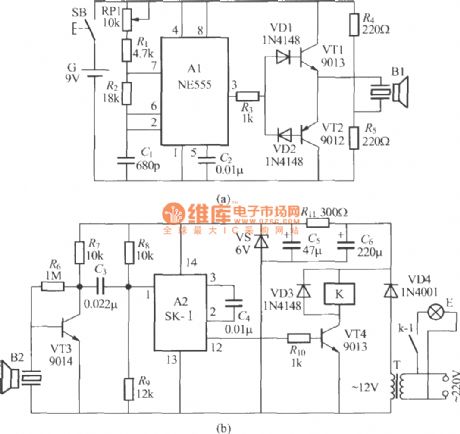
Ultrasonic is invisible, it will not interfere the household appliances, so it is popular among some occasions. The figure is as shown, it is a practical ultrasonic remote control light switch, it consists of ultrasonic remote control transmitter and receiver. The ultrasonic remote control transmitter circuit is shown as figure (a), the 40kHz free running multivibrator is composed of NE555 time base circuit A1, outputed from ③ foot, the electrical signal radiates ultrasound remote control command by VT1, VT2 amplifying and driving ultrasonic transducer B1. RP1 is trimmer resistor, it can adjust oscillation frequency to ensure it work with 40kHz. The ultrasonic remote control receiver circuit is shown as figure (b). It is composed of ultrasonic reception transducer B2, preamplifier VT3, sound control special IC A2, electronic switch and power supply. (View)
View full Circuit Diagram | Comments | Reading(2979)
TC9307AF-008 digital-tuning microprocessor integrated circuit
Published:2011/4/25 20:23:00 Author:TaoXi | Keyword: digital-tuning, microprocessor
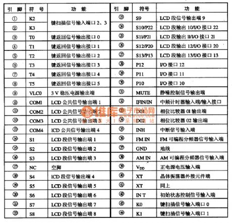
The microprocessor TC9307AF-008 has all functions of the DTS, this means the TC9307AF-008 has the 130MHz prescaler, PLL frequency synthesizer and the LCD driver. If TC9307AF-008 combined with the TD6135AP prescaler, they can receive TV's (VHF, UHF) all channel programs. The digital tuning system which is formed by this IC has the following main functions:
(1)Manual up/down tuning, auto scan tuning, fast tuning and automatic storage tuning.
(2)Can preset 20 radio frequencies and the last radio frequency you have heard.
(3)Clock display with I2h/24h and TIMER function, sleep function.
1.Circuit block diagram and pin functions of the TC9307AF-008:
Figure1. Circuit block diagram and pin functions of the TC9307AF-008.
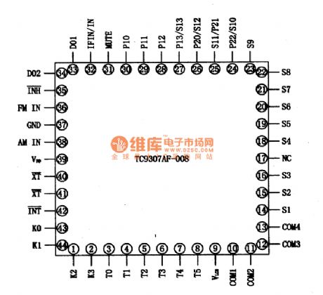
Figure 2. Manifold's pin arrangement of the TC9307AF-008
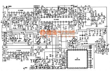
2. Typical application circuit of the TC9307AF-008
Figure 3. Typical application circuit of the TC9307AF-008.
3. Signal process
4. Tips of breakdown (View)
View full Circuit Diagram | Comments | Reading(3060)
BA5104/BA8207K multi-function infrared remote control electric fan with the sound of crickets circuit diagram
Published:2011/4/24 10:26:00 Author:Rebekka | Keyword: electric fans , infrared remote control
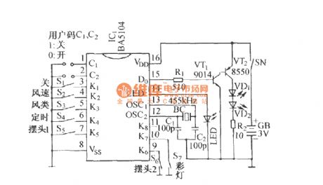
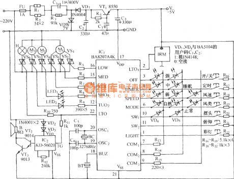
BA5104 coded remote control transmitter circuit:
BA8207K multifunctional infrared remote controlfan with the sound of cricketscircuit:
(View)
View full Circuit Diagram | Comments | Reading(2696)
Wind Turbine Schematic Circuit
Published:2011/4/25 7:26:00 Author:Robert | Keyword: Wind Turbine
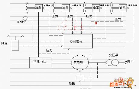
Wind Turbine SchematicCircuit is shown above. (View)
View full Circuit Diagram | Comments | Reading(1318)
Darkroom Exposure Timer Lamp Circuit
Published:2011/4/22 4:23:00 Author:Christina | Keyword: Darkroom Exposure, Timer Lamp
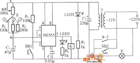
The darkroom exposure timer lamp circuit is as shown, the ne555 time base circuit and the potentiometer rp, capacitor c form the single-stable trigger. Usually the circuit is in reset state, pin-3 of ne555 send out the low-level current, relay K does not operate, exposure light E does not shine. LED led2 is designed as the indicator light, this indicator lightilluminates the dial of potentiometer rp. At this point the internal discharge of ne555 is conducted, capacitor C1 is shorted and can not be charged. k can be the small medium-power electromagnetic relay such as jzc-22f and dc12v.
(View)
View full Circuit Diagram | Comments | Reading(730)
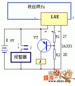
Infrared Ray Probe Alarm Circuit
Published:2011/4/22 3:22:00 Author:Christina | Keyword: Infrared Ray, Probe, Alarm
The Infrared Ray Probe Alarm Circuit is as shown:
(View)
View full Circuit Diagram | Comments | Reading(584)
Photoresistor Light Control Switch Circuit
Published:2011/4/24 19:23:00 Author:Christina | Keyword: Photoresistor, Light Control Switch
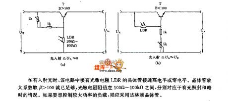
When there is incident light,the transistor of LDR photoresistor connected to the high or zero level. Amplification factor of transistor is β>100, resistance of the photoresistor is between 100 ohms to 100 kilohms, correspond to the bright light and dark conditions. If you want to control the high power load, the darlington transistor should be used. (View)
View full Circuit Diagram | Comments | Reading(2786)
Touch Delay Switch Circuit Composed of NAND Gate
Published:2011/4/25 2:43:00 Author:TaoXi | Keyword: NAND Gate, Touch Delay Switch
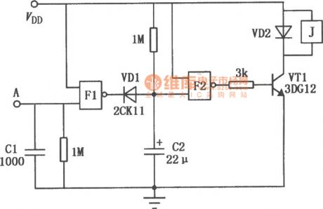
The Touch Delay Switch Circuit Composed of NAND Gate is as shown:
(View)
View full Circuit Diagram | Comments | Reading(725)
Light Delay Switch Circuit Composed Of Inverter
Published:2011/4/25 2:45:00 Author:TaoXi | Keyword: Inverter, Light Delay Switch
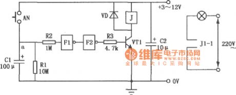
The Light Delay Switch Circuit Composed Of Inverter is as shown:
(View)
View full Circuit Diagram | Comments | Reading(560)
Circuit of Electronic Selector Switch Composed of CD4017 and CD4066
Published:2011/4/25 2:46:00 Author:TaoXi | Keyword: Electronic, Selector Switch
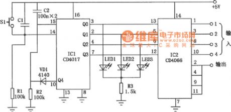
The Circuit of Electronic Selector Switch Composed of CD4017 and CD4066 is as shown:
(View)
View full Circuit Diagram | Comments | Reading(7024)
TC9316F digital tuning DTS integrated circuit
Published:2011/4/25 9:14:00 Author:TaoXi | Keyword: digital tuning, DTS
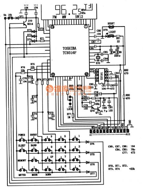
The TC9316F is produced by the Toshiba company, this device is one kind of DTS integrated circuits and is designed for the digital tuning radio, you can input the radio frequency directly, and it can presets 24 radio programs.
1.TC9316F circuit functions
The built-in LCD driver of TC9136F can output 1/4 duty cycle, 1/3 bias, the repetition frequency is 125Hz drive pulse segment. It has PLL9lKHz, 10KHz reference frequencies and 75kHz, 15OKHz crystal oscillator to choice, the program controls the reference frequency, the command execute time is 80μS and 40μs. The PLL circuit includes the second division mathematical model's FM prescaler, the 4-bit frequency counter, 12-bit programmable divider, and the phase comparator.etc functions, and this circuit sets up a special 16-bit general-purpose IF counter.
2.TC9316F typical application circuit
The TC9316F typical application circuit is shown as figure 1, use the keyboard matrix to set 19 operation keys. If we use the diode as the jumper, there are 32 operation keys to set.
Figure 1. The TC9316F typical application circuit
The TC9316F connected with the front circuit by 12 leads.
(1)BO, B1 connected with the external decoder, it used to control the band selection, if one wave band has no channel, you should focus on checking this circuit.
(2)OWER can be used to start the power, if there is no high-level signal sent out by the TC9316F, the radio circuit will not work.
Table 1. The pin functions and data tables of the TC9316F IC (View)
View full Circuit Diagram | Comments | Reading(1958)
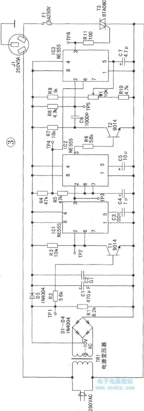
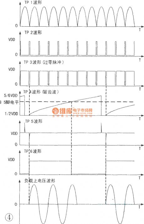
SCR over zero trigger voltage regulator
Published:2011/4/22 6:41:00 Author:May | Keyword: SCR, over zero, trigger voltage regulator
View full Circuit Diagram | Comments | Reading(1024)
555 temperature interval control circuit
Published:2011/4/25 3:49:00 Author:May | Keyword: 555, temperature interval, control
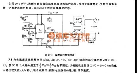
As shown in diagram 20-3, control circuit includes step-down rectifying parts and temperature control parts. It is used for keeping certainly temperature interval occasions such as poultry hatching, biotic experiment, etc. IC (555) works on the state of dual stable mode.
RT is negative temperature factor thermistance (3kΩ), RT, R2~R4, RP1, RP2 make up control temperature divider voltage network. It can make pin 2, 6 of IC separately located in near 1/3VDD and 2/3VDD level by adjusting RP1 and RP2, in order to set or reset along with the changing of setting temperature (20℃~100℃), and it can pulled in or cut off J1, it can control the breaking over, cut off of electric heater, and it can adjust the temperature. (View)
View full Circuit Diagram | Comments | Reading(1354)
NiMH / Ni-Cd battery fast charging controller AIC1783 circuit
Published:2011/4/22 6:15:00 Author:May | Keyword: NiMH / Ni-Cd battery, fast, charging controller
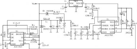
View full Circuit Diagram | Comments | Reading(760)
| Pages:282/312 At 20281282283284285286287288289290291292293294295296297298299300Under 20 |
Circuit Categories
power supply circuit
Amplifier Circuit
Basic Circuit
LED and Light Circuit
Sensor Circuit
Signal Processing
Electrical Equipment Circuit
Control Circuit
Remote Control Circuit
A/D-D/A Converter Circuit
Audio Circuit
Measuring and Test Circuit
Communication Circuit
Computer-Related Circuit
555 Circuit
Automotive Circuit
Repairing Circuit