
Index 289
The fridge over voltage, under voltage, power delay protector composed of 556
Published:2011/4/19 3:08:00 Author:Ecco | Keyword: fridge, over voltage, under voltage, power delay , protector
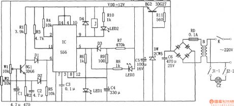
The chart shows a fridge over voltage, under voltage, power delay protector circuit. The circuit consists of over and under voltage sampling circuit, trigger circuit, delay circuit, the buck rectifier circuit. And the buck rectifier circuit provides DC voltage for the entire circuit.
(View)
View full Circuit Diagram | Comments | Reading(3639)
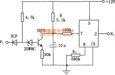
Delay circuit with JEC-2 (2)
Published:2011/4/19 1:56:00 Author:Jessie | Keyword: Delay
View full Circuit Diagram | Comments | Reading(534)
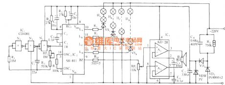
SH-811 festival color lamp with piano music automatic program control circuit
Published:2011/4/19 1:44:00 Author:Nicole | Keyword: festival color lamp, piano music, program control
View full Circuit Diagram | Comments | Reading(572)
SH-818 seven functions color lamp and good quality piano music automatic control circuit
Published:2011/4/19 1:26:00 Author:Nicole | Keyword: color lamp, piano music
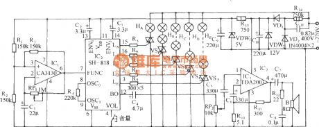
As shown in the figure, it consists of clock beat generator, light control circuit, middle power amplifier and AC depressurization, steady voltage circuit. CA3130(IC1) is a BiMOS single operational amplifier, it with RP1, R3, C1 will from a self-excited oscillator, the oscillation frequency depends on the charge and discharge time of RP1, C1. Its output beat pulse is used as SH-818 function control pulse. (View)
View full Circuit Diagram | Comments | Reading(507)
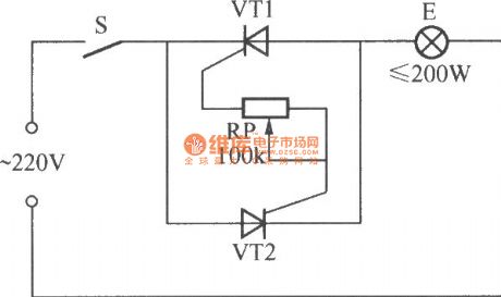
Simplest bidirectional SCR dimming light circuit
Published:2011/4/19 0:56:00 Author:Nicole | Keyword: bidirectional SCR, dimming light
As shown in the figure, this is a simplest bidirectional SCR dimming light circuit, the feature of it is that adding proper trigger pulse or control current to its control pole, it will turn on whether it is AC positive half cycle or negative half cycle, the conduction time depends on the pulse width and gate current. To adjust RP will change the brightness of bulb E. (View)
View full Circuit Diagram | Comments | Reading(915)
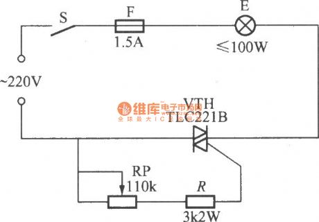
Simplest unidirectional SCR dimming light circuit
Published:2011/4/19 0:46:00 Author:Nicole | Keyword: unidirectional SCR, dimming light
As shown in the figure, this is a simplest unidirectional SCR dimming light circuit, the two 3~5A/600V unidirectional SCR are antiparallel, their gates are connected by a 100kΩ potentiometer, then they form a stepless dimmer with 200W load. (View)
View full Circuit Diagram | Comments | Reading(2863)
Showcase or bulletin board timing light controllor circuit(1)
Published:2011/4/18 23:50:00 Author:Nicole | Keyword: showcase or bulletin board, timing light, controllor
As shown in the figure, it is a showcase or bulletin board timing light controllor composed of two electronic tables, the electronic table 1 is used to set everyday lighting up time, the electronic table 2 is used to set everyday turn-off light time. (View)
View full Circuit Diagram | Comments | Reading(508)
Relay pull-in timer circuit in time process
Published:2011/4/18 22:30:00 Author:Nicole | Keyword: relay, timer, time process
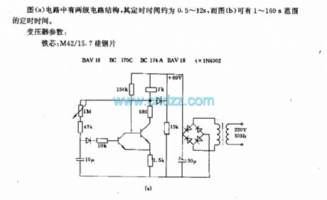
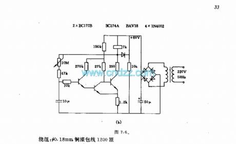
In figure (a), the circuit has two-stage circuit structures, the timing time is about 0.5~12s, and in figure (b), the range of the timing time is 1~160s.
The parameters of transformer: iron chip: M42/15.7 silicon steel sheet; winding: Φ0.18mm, enameled copper wire 1200turns.
(View)
View full Circuit Diagram | Comments | Reading(1772)
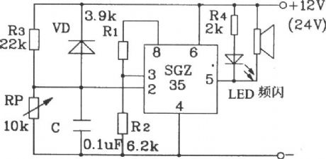
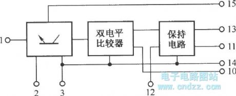
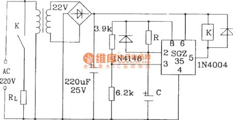
Storage battery voltage alarm circuit composed of SGZ35 time control integrated circuit
Published:2011/4/18 20:42:00 Author:Nicole | Keyword: storage battery, alarm, time control
View full Circuit Diagram | Comments | Reading(490)
Multifunction delay floodlight control circuit composed of YH2902A multifunction timing control module
Published:2011/4/18 22:14:00 Author:Nicole | Keyword: delay floodlight, timing control module
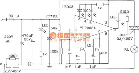
Multifunction delay floodlight control circuit composed of YH2902A. Rx=120kΩ, Cx=1pF, and t=1/1(0.7~1)·Rx·Cx], then this circuit can achieve delay 5mins, 15mins, 30mins and uncertain time four kinds working processes. (View)
View full Circuit Diagram | Comments | Reading(564)
Low voltage light timing flashing circuit
Published:2011/4/18 20:05:00 Author:Nicole | Keyword: Low voltage light, timing flashing
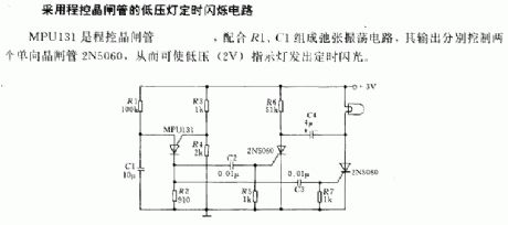
MPU131 is program control SCR, with R1, C1 form flip-flow oscillation circuit, the output control two unidirectional SCR 2N5060, then the low voltage (2V) indicator light will send out timging flashing. (View)
View full Circuit Diagram | Comments | Reading(1192)
Valve control temperature adjusting circuit
Published:2011/4/18 0:30:00 Author:Nicole | Keyword: Valve control, temperature adjusting

This temperature control circuit can control 220V servo motor to turn left or right, its static range can be adjusted. The bae of push pull stage is controlled by feedback amplifier TAA861, switches T3 and T4 each controls its relay to make the motor turn left or right.
The temperature testing adopts R1~R6 bridge circuit, the sensor is K274 thermal resistor, using potentiometer R1 to pre-select the given temperature.
The main technical data: the work voltage: 18V; the temperature range: 25~95℃; the highest temperature of sensor: 100℃; the temperature difference within ±10% power voltage wave motion: < 0.1°K; the adjustable static region: 0.2~1°K.
(View)
View full Circuit Diagram | Comments | Reading(1483)
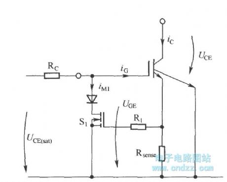
Limiting short circuit current by reducing IGBT grid-emission voltage
Published:2011/4/10 22:55:00 Author:may | Keyword: limiting short circuit , IGBT grid-emitting stage voltage
View full Circuit Diagram | Comments | Reading(588)
The internal structure of HL601A
Published:2011/4/14 6:29:00 Author:may | Keyword: internal structure
HL601A is thick film integrated circuit.It can achieve dual-level protection of signal's over current, over voltage, over heating, etc. Its features include precise threshold, fast speed, and high reliability. (View)
View full Circuit Diagram | Comments | Reading(615)
Delay lamp controller circuit composed of CD4017
Published:2011/3/24 21:47:00 Author:may | Keyword: Delay lamp controller
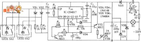
Delay lamp controller circuit composed of CD4017 is shown in the following diagram:
(View)
View full Circuit Diagram | Comments | Reading(758)
Delay circuit composed of SGZ35 time control integrated circuit
Published:2011/4/18 20:40:00 Author:Nicole | Keyword: delay, time control
View full Circuit Diagram | Comments | Reading(446)
Temperature protection circuit composed of U2403B constant current charging timer
Published:2011/4/18 20:38:00 Author:Nicole | Keyword: temperature protection, constant current, charging timer
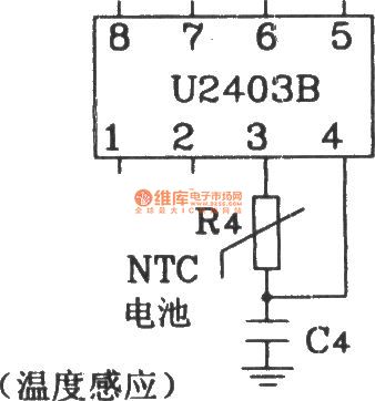
View full Circuit Diagram | Comments | Reading(419)
Power failure alarm circuit
Published:2011/4/18 20:33:00 Author:Ecco | Keyword: Power failure , alarm circuit
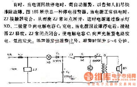
Sometimes, when the power is black out for some reasons, it needs to alarm automatically to inform people overcoming the breakdown as soon as possible. Figure 185 shows a power failure alarm. When power supply works normally, ZJ contactors pull in, so that the ZJ normal closed contact cuts off, then power is charging by the electrolytic capacitor C1 between the lights XD and diode D. When the power is black out for some reasons, ZJ contactors release, so that electrolytic capacitor C1 discharges to the sound and light alarm circuit, neon light bulbs turn on, speakers emit alarm signals, the alarm time is 5 to 6 minutes.
(View)
View full Circuit Diagram | Comments | Reading(754)
800W three-terminal bidirectional thyristor dimmer circuit
Published:2011/4/5 20:44:00 Author:may | Keyword: 800W, three-terminal, bidirectional thyristor, dimmer
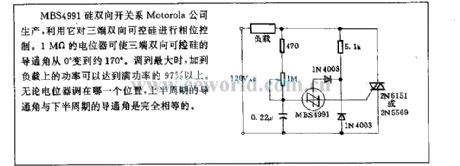
MBS4991 silicon bilateral switch is produced by Motorala company. We can utilize it to control phase of three-terminal bidirectional thyristor. 1MΩ regulation resistance can let the turn-on angle of three-terminal bidirectional thyristor changing from 0° to about 170°. When adjusting to maximum, the power added to load can reach 97% of full power. Now matter what the posistion the regulation resistance is, turn-on angle of upper half period and the turn-on angle of lower half poriod is exatly equal.
(View)
View full Circuit Diagram | Comments | Reading(1173)
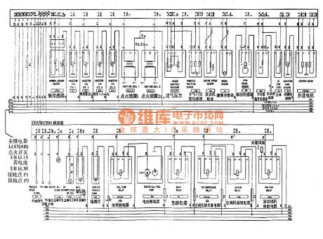
General WuLing united electronics electric control system circuit
Published:2011/4/18 7:42:00 Author:Jessie | Keyword: united electronics, electric control system
View full Circuit Diagram | Comments | Reading(522)
| Pages:289/312 At 20281282283284285286287288289290291292293294295296297298299300Under 20 |
Circuit Categories
power supply circuit
Amplifier Circuit
Basic Circuit
LED and Light Circuit
Sensor Circuit
Signal Processing
Electrical Equipment Circuit
Control Circuit
Remote Control Circuit
A/D-D/A Converter Circuit
Audio Circuit
Measuring and Test Circuit
Communication Circuit
Computer-Related Circuit
555 Circuit
Automotive Circuit
Repairing Circuit