
Index 283
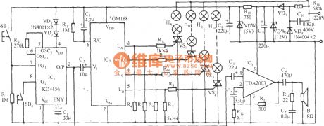
5GM168 "mandarin duck jump" lantern loop control with birdsong circuit
Published:2011/4/25 4:40:00 Author:May | Keyword: lantern loop control, birdsong
View full Circuit Diagram | Comments | Reading(529)
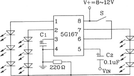
Typical application circuit of 5G167 synchronous Lantern ring control integrated circuit
Published:2011/4/25 4:42:00 Author:May | Keyword: synchronous Lantern, ring control, integrated circuit
View full Circuit Diagram | Comments | Reading(809)
MCP component MMl521XV internal block diagram and protection circuit
Published:2011/4/25 3:33:00 Author:Nicole | Keyword: MCP component
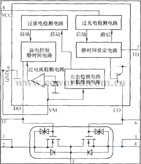
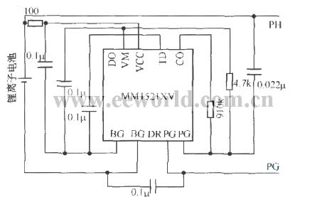
MCP is a multi-package produce, it can put the integrated protection circuit and charge-discharge circuit into the same package. The internal block diagram is shown as below:
(View)
View full Circuit Diagram | Comments | Reading(673)
Dark room exposure timing light circuit(2)(BA225F)
Published:2011/4/24 22:58:00 Author:Nicole | Keyword: dark room, timing light
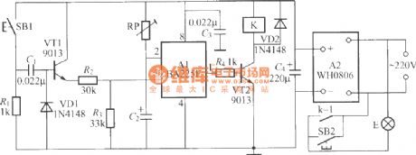
The figure is as shown, it is a dark room exposure timing light with novel timing IC. In figure, BA225F is a novel double timing IC produced by Toyo electric appliance, it contains two independent timers, this circuit only uses one of them, the timing time can be from a few milliseconds to a few minutes, the feature of it is: low power consumption(the typical value is 0.75mA), a few peripheral components, wide work voltage range and so on. (View)
View full Circuit Diagram | Comments | Reading(823)
Dark room exposure timing light circuit(1)
Published:2011/4/25 0:58:00 Author:Nicole | Keyword: Dark room, timing light
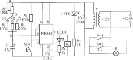
The figure is as shown, it is a dark room exposure timing light circuit which is suitable for black-and-white photographyblowing down Photos, the monostable trigger is composed of NE555 time base circuit and potentiometer RP, capacitance C. In normal times, the circuit is in resetting state, NE555's ③ foot output is low level, relay K is no action, exposing lamp E is off. LED2 is work indicating light, it can light up the calibrated disc of potentiometer RP. At this time, NE555 internal discharge tube turns on, capacitance C1 is short-circuited, it can not charge. K can adopt JZC-22F、DC12V small middle power electromagnetic relay. (View)
View full Circuit Diagram | Comments | Reading(980)
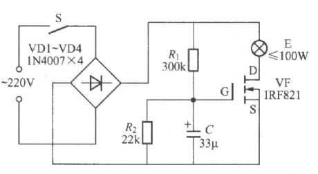
Incandescent lamp life extension switch circuit
Published:2011/4/25 1:05:00 Author:Nicole | Keyword: incandescent lamp, life extension, switch
View full Circuit Diagram | Comments | Reading(562)
Vehicle flashing lights controller 6
Published:2011/4/21 4:19:00 Author:Ecco | Keyword: Vehicle , flashing lights , controller
(View)
View full Circuit Diagram | Comments | Reading(648)
CMos drive circuit used in LCD
Published:2011/4/25 2:49:00 Author:Nicole | Keyword: LCD, CMos drive
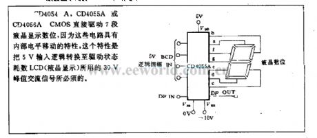
CD4054A, CD4055A or CD4056A CMOS directly drive 7 segment LCD digit, because this circuit has the characteristic of internal PWL movement, this characteristic is needed by 30V peak AC singal, the singal is used to transform 5V input logic into drive state. (View)
View full Circuit Diagram | Comments | Reading(825)
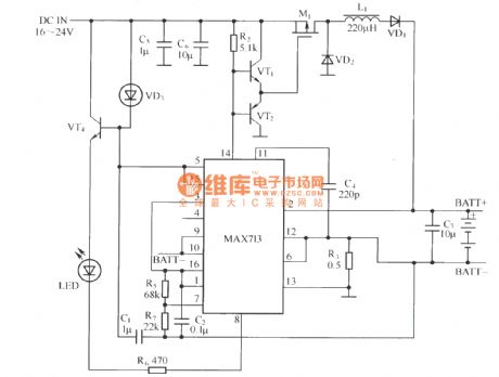
MAXTl3 switch mode application circuit
Published:2011/4/25 3:10:00 Author:Nicole | Keyword: switch mode
View full Circuit Diagram | Comments | Reading(437)
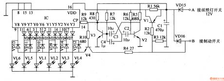
Vehicle flashing lights controller 3
Published:2011/4/21 4:09:00 Author:Ecco | Keyword: Vehicle , flashing lights , controller
(View)
View full Circuit Diagram | Comments | Reading(659)
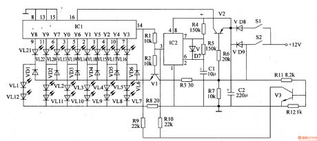
Vehicle flashing lights controller 2
Published:2011/4/21 3:54:00 Author:Ecco | Keyword: Vehicle , flashing lights , controller
The motor vehicle flashing lights controller described in the example is composed of LED light-emitting diodes and the relative control circuit. The LED light-emitting diodes are made in various designs and installed of the rear window part of the motorcycle or car, when driving at night, the light-emitting diode is lit like the water cycle; when braking, all light-emitting diode are flashing to remind the following vehicle.
The working principleThe motor vehicle flashing lights controller is composed of electronic filter circuit, the multivibrator circuit and the LED control display circuit, it is shown in Figure 7-26.
When the YO or Y6 of IC outputs high level, VLl light emitting diode in 1 Road is lit.
When the Y1 or Y5 of IC outputs high level, VL2 light emitting diode in2 Road is lit.
When the Y3 of IC outputs high level, VL4 light emitting diode in4 Road is lit.
When the Y7 or Y9 of IC outputs high level, VL3 light emitting diode in5 Road is lit.
When the Y2 or Y4 of IC outputs high level, VLl light emitting diode in3 Road is lit.
When the Y8 of IC outputs high level, VL6 light emitting diode in6 Road is lit.
(View)
View full Circuit Diagram | Comments | Reading(1335)
Three phase three-wire system phase failure protection circuit
Published:2011/4/24 21:20:00 Author:Nicole | Keyword: three phase, three-wire system, phase failure
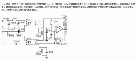
This is a three phase three-wire system power supply phase failure protection circuit, if lacking any phase of A, B, C, the optic coupler output level is lower than the reference voltage of comparator reverse-phase input terminal, comparator outputs low level, to lock PWM drive singal, cuting off the power supply. If changing the comparator input polarity, it also can use high level to lock PWM singal. This phase failure protection circuit adopts optical coupler to isolate heavy current, it is secure and reliable, RP1, RP2 is used to adjust phase failure protection motion threshold value. (View)
View full Circuit Diagram | Comments | Reading(2440)
Timer circuit with Miller integrator
Published:2011/4/24 21:30:00 Author:Nicole | Keyword: timer, Miller integrator
Miller integrator's negative feedback is connected from transistor collector to its base by capacitance. It adopts composite pipe to improve the current amplification.
After pressing key T, the capacitance is charged to power voltage. The time constant of this process is 33ms. Relay is no delay pull-in. When the key is cut off, Miller integrator starts to work. (View)
View full Circuit Diagram | Comments | Reading(728)
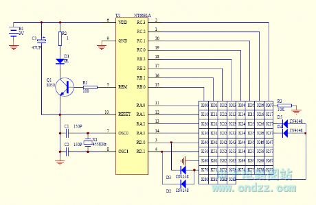
Multi-code monolithic remote controller
Published:2011/4/24 21:07:00 Author:Ecco | Keyword: Multi-code , monolithic , remote controller
View full Circuit Diagram | Comments | Reading(840)
Radio Remote Control Fan Speed Controller Circuit
Published:2011/4/24 19:59:00 Author:Christina | Keyword: Radio Remote Control, Fan Speed Controller
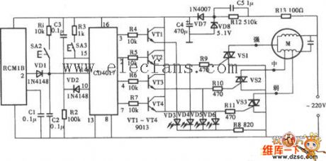
The Radio Remote Control Fan Speed Controller Circuit is as shown.
The circuit is composed of the CD4017 and RCM1B, electric motor.etc., the circuit is very simple. (View)
View full Circuit Diagram | Comments | Reading(1400)
Audio Commentary Synchronous Controller Circuit
Published:2011/4/23 23:10:00 Author:TaoXi | Keyword: Audio Commentary, Synchronous Controller
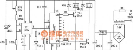
The Audio Commentary Synchronous Controller Circuit is as shown:
(View)
View full Circuit Diagram | Comments | Reading(500)
Squirrel Cage Autotransformer Motor Starter Circuit
Published:2011/4/23 3:02:00 Author:Robert | Keyword: Squirrel Cage, Autotransformer, Motor Starter
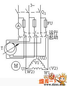
Squirrel Cage Autotransformer Motor Starter Circuit is shown above. (View)
View full Circuit Diagram | Comments | Reading(1449)
Squirrel Cage Motor Direct Starting Circuit
Published:2011/4/23 3:07:00 Author:Robert | Keyword: Squirrel Cage, Motor, Direct Starting
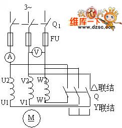
Squirrel Cage Motor Direct Starting Circuit is shown above. (View)
View full Circuit Diagram | Comments | Reading(852)
Electric Fan Multi-Function Sound Control Speed Governing Circuit
Published:2011/4/23 3:09:00 Author:Robert | Keyword: Electric Fan, Multi-Function, Sound Control, Speed Governing
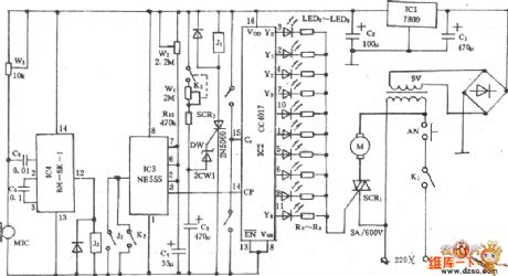
Electric Fan Multi-Function Sound Control Speed Governing Circuit is shown below:
(View)
View full Circuit Diagram | Comments | Reading(620)
Electric Fan Sound Control Speed Governing Circuit
Published:2011/4/23 3:17:00 Author:Robert | Keyword: Electric Fan, Sound Control, Speed Governing
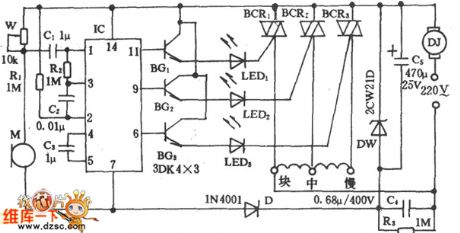
Electric Fan Sound Control Speed Governing Circuit is shown below:
(View)
View full Circuit Diagram | Comments | Reading(802)
| Pages:283/312 At 20281282283284285286287288289290291292293294295296297298299300Under 20 |
Circuit Categories
power supply circuit
Amplifier Circuit
Basic Circuit
LED and Light Circuit
Sensor Circuit
Signal Processing
Electrical Equipment Circuit
Control Circuit
Remote Control Circuit
A/D-D/A Converter Circuit
Audio Circuit
Measuring and Test Circuit
Communication Circuit
Computer-Related Circuit
555 Circuit
Automotive Circuit
Repairing Circuit