
Index 291
LC182 audio voltage control christmas tree color lamp control circuit
Published:2011/4/18 7:40:00 Author:Nicole | Keyword: audio, voltage control, christmas tree, color lamp
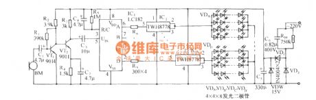
The circuit is as shown. It consists of pick up singal amplifier, LC182 light control cirucit, power drive switch circuit, multi colors LED and AC depressurization rectifier circuit. (View)
View full Circuit Diagram | Comments | Reading(988)
Festival color lamp control circuit using BH9201
Published:2011/4/18 7:26:00 Author:Nicole | Keyword: color lamp
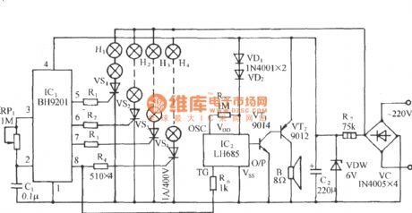
The circuit is as shown, it is composed of light control circuit, firecracker phonation circuit and AC depressurization rectifier circuit. This circuit has few components, much color lamp transformation, good sound and light effect. (View)
View full Circuit Diagram | Comments | Reading(493)
Typical application circuit of audio color lamp control integrated circuit ECl89
Published:2011/4/18 7:12:00 Author:Nicole | Keyword: audio, color lamp
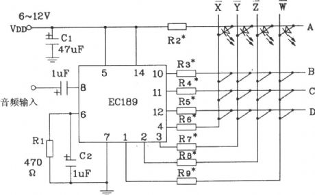
This circuit can combine and arrange many colors LED with a method, it can reach a variety of color flashing effects such as rotation, rotation, flowing water, linear and radial cycle. (View)
View full Circuit Diagram | Comments | Reading(551)
AC/DC general motor rotational speed and power regulation circuit
Published:2011/4/18 1:08:00 Author:Nicole | Keyword: AC motor, DC motor, rotational speed, power

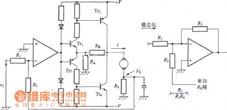
In AC/DC general motor(commutator motor), excitation winding in series with armature winding, so in AC power supply, the field direction and armature current direction is changed synchronously, so the rotation direction is not changed. Figure (a) shows its typical characteristic curve, figure (b) shows the relationship curve between motor rotational speed and conduction angle, figure (c) is steady speed circuit. The control angle is relative to the voltage on RC link in trigger loop, this voltage is the difference between applied voltage and armature voltage, so it has the function of negative feedback stabilizes rotational speed. (View)
View full Circuit Diagram | Comments | Reading(1051)
Upper, lower limit temperature control with acoustics report calling circuit(MAX6502/3)
Published:2011/4/18 2:16:00 Author:Nicole | Keyword: temperature control, acoustics report calling

View full Circuit Diagram | Comments | Reading(429)
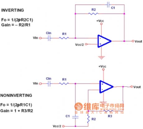
Operation amplifier low-pass filter circuit
Published:2011/4/17 21:08:00 Author:Jessie | Keyword: Operation amplifier low-pass filter
View full Circuit Diagram | Comments | Reading(720)
Operation amplifier venturi filter circuit diagram
Published:2011/4/13 20:18:00 Author:Jessie | Keyword: Operation amplifier, venturi filter
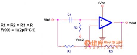
For all frequencies venturi filters are the same gain, but it can change the angle of signals, it also can be used for angle correction circuit at the same time. Circuit has a 90 degrees' phase shift on the signal frequency F,a0 degree's phaseshifton dc, and a 180 degrees' phase shifton the high frequency. (View)
View full Circuit Diagram | Comments | Reading(783)
Operation multi-feedback filter circuit
Published:2011/4/13 21:07:00 Author:Jessie | Keyword: Operation, multi-feedback, filter
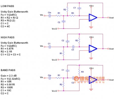
Multi-feedback filteris a universal, low cost and easy implementing filter. Unfortunately, the calculation of designing is a littlecomplex, here without in-depth introduction. Please see the reference which introducts multi-feedback filter in the details. If need a unity-gain Butterworth filter, then this circuit can give a similar result. (View)
View full Circuit Diagram | Comments | Reading(834)
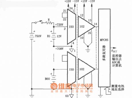
The battery monitoring circuit in the high-voltage charging circuit with ISO102
Published:2011/4/18 4:38:00 Author:Jessie | Keyword: The battery monitoring, high-voltage charging
View full Circuit Diagram | Comments | Reading(530)
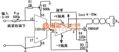
4~20mA Isolation analog (ISO100) circuit
Published:2011/4/18 4:27:00 Author:Jessie | Keyword: Isolation analog
View full Circuit Diagram | Comments | Reading(818)
4302 Division circuit
Published:2011/4/14 20:35:00 Author:Jessie | Keyword: 4302 Division
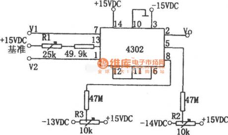
As shownis the division circuit composed by integrated block 4302, the inputs are V1 and V2, its output Vo is: Vo=10V1/V2. The input signal range: 0.03V≤V1≤10V, 0.03V≤V2≤10V. The circuit's typical error is ±25mV at 25℃, the max error is ±50mV, and output voltage accuracy affected by temperature, its temperature coefficient is ±1mV/C, output disorders voltage is 士10mV at 25℃, temperature coefficient is ±lmV/C. V1, V2's bandwidth in small signal is 500 kHzin small signal (-3dB), full range output is 60kHz. The adjustment method ofR1, R2 and R3 is: when V1=V2=+10V, adjust R1 to make the output Vo = +10V; When Vl=V2=+0.1V, adjust R2 to make output Vo=+10V; When V1=+0.01V, V2=+0.1V, adjust R3 to make Vo=+1V. So can adjust again and againfor a few times. (View)
View full Circuit Diagram | Comments | Reading(811)
Pyroelectric infrared sensor induction control circuit 1
Published:2011/4/12 3:41:00 Author:Jessie | Keyword: Pyroelectric infrared, sensor induction control
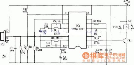
This type of control circuit mainly consists of pyroelectric infrared sensor and amplifying circuit. Pyroelectric infrared sensor isa new type of sensitive components, it is made from high thermoelectric coefficient materialswith impedance matching mosfet and filter piece. Pyroelectric infrared sensor is able to detect infrared ray radiation human issued in contactless manner, and translate it into electrical signal to send out.
(View)
View full Circuit Diagram | Comments | Reading(1813)
The current control circuit using discrete transistor
Published:2011/4/12 3:38:00 Author:Jessie | Keyword: discrete transistor, current control
View full Circuit Diagram | Comments | Reading(802)
Insulation DC voltage detected circuit diagram
Published:2011/4/12 3:37:00 Author:Jessie | Keyword: Insulation DC voltage detected

View full Circuit Diagram | Comments | Reading(365)
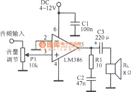
LM386 typical applications circuit
Published:2011/4/12 3:37:00 Author:Jessie | Keyword: typical applications
View full Circuit Diagram | Comments | Reading(1390)
Small and medium-sized DC motor structure diagram
Published:2011/4/11 23:02:00 Author:Jessie | Keyword: Small and medium-sized, DC motor structure
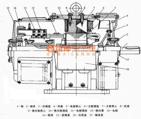
View full Circuit Diagram | Comments | Reading(1423)
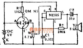
Simple combustible gas alarm circuit
Published:2011/4/11 23:54:00 Author:Jessie | Keyword: Simple, combustible gas, alarm
View full Circuit Diagram | Comments | Reading(626)
MC1594 AC voltage multiplier circuit
Published:2011/4/14 22:02:00 Author:Jessie | Keyword: AC voltage, multiplier
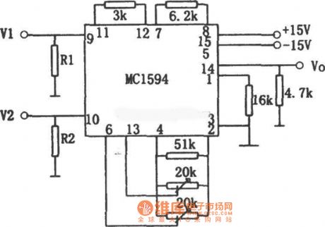
This circuit is composed by four quadrant multiplier MC1594, the circuit issimple, the accuracy is a bit poor. In order to make the circuit works in linear area, input resistance R1 and R2's values depend on the input voltage's value. R1 equals to V1 multiplied by 6, R2 equals to V2 multiplied by three. If V1=V2=3V, then R1=18kΩ, R2=9kΩ.When there aredifferent input voltages, generally R1=52kΩ, R2=30kΩ, but that would make precision and linearity fell. The relationship of input and output is Vo=V1V2/10. (View)
View full Circuit Diagram | Comments | Reading(1115)
Family karaoke lighting control circuit composed of 5GM168
Published:2011/3/23 23:24:00 Author:may | Keyword: 5GM168
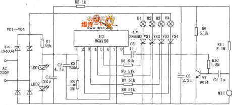
The design method of family karaoke lighting control is varied, here introduced control circuit is a application circuit with four load light ouput, jump circulate, speed controlable. Light jump speed change along with microphone received voice signal strong or weak, voice signal more strong, light jump faster, or speed is slow. Family karaoke lighting control circuit is shown in the diagram. This circuit mainly consists of power supply circuit, control circuit and audio-frequency amplifier.
(View)
View full Circuit Diagram | Comments | Reading(1222)
Power line load V, I and P isolation detection circuit
Published:2011/4/18 0:51:00 Author:Jessie | Keyword: Power line load V, I and P, isolation detection
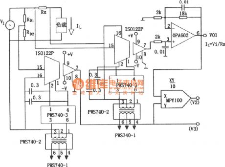
View full Circuit Diagram | Comments | Reading(598)
| Pages:291/312 At 20281282283284285286287288289290291292293294295296297298299300Under 20 |
Circuit Categories
power supply circuit
Amplifier Circuit
Basic Circuit
LED and Light Circuit
Sensor Circuit
Signal Processing
Electrical Equipment Circuit
Control Circuit
Remote Control Circuit
A/D-D/A Converter Circuit
Audio Circuit
Measuring and Test Circuit
Communication Circuit
Computer-Related Circuit
555 Circuit
Automotive Circuit
Repairing Circuit