
Index 292
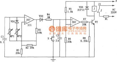
High precision timer circuit with op-amp SF357
Published:2011/4/18 0:53:00 Author:Jessie | Keyword: High precision timer, op-amp
View full Circuit Diagram | Comments | Reading(1343)
Liquid level alarm circuit which controlled by integrated circuit promixity switches
Published:2011/3/23 3:02:00 Author:Jessie | Keyword: Liquid level alarm, integrated circuit
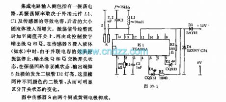
Integrated circuit input side has a oscillating circuit,it's oscillation frequency depends on external components L1, C1 and sensor's equivalent capacitance, the latter size increases with liquid immersion. Oscillating signal add on the threshold switch after rectified, then control digital output level. When the sensor S dipped into the liquid, Oscillation stop because the effects of shunt capacitance, output gradesexchange the switch state. (View)
View full Circuit Diagram | Comments | Reading(1457)
Use uc3907 design mature average current circuit
Published:2011/3/29 4:23:00 Author:Jessie | Keyword: average current

From the structure of UC3907, itcan be divided into voltage loop and current loop two parts. Voltage loop is composed by voltage amplifier,and the driver amplifier; Current loop is composed by current amplifier, adjust amplifiers, buffer amplifier and state instructions constitutes. UC3907's pin 14 outputs between 1.5 V and 2.25 V, pin 6, 7 constitute a loop with resistance R1, R2, emitter is about 150 V.
(View)
View full Circuit Diagram | Comments | Reading(1016)
Relay control circuit
Published:2011/3/29 3:47:00 Author:Jessie | Keyword: Relay
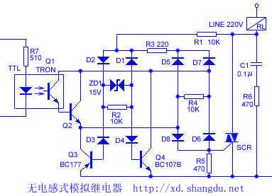
220V power provide bias for Q3, Q4 at positive and negative half cycle by load RL, R1, D1 ~ D4, ZD1; Meanwhile it provides power for photoelectric coupler by R3, D5 ~ D8. When TTL circuit outputs signal of high level, photoelectric coupler connected in positive half cycle, so produces voltage drop in R5 ends, trigger SCR connected, load RL works. The whole circuit's functionis likea relay, but won't produce reverse induced voltage, and avoid load being damaged by high back voltage.
(View)
View full Circuit Diagram | Comments | Reading(779)
Delay 0.2-10s circuit
Published:2011/3/27 20:58:00 Author:Jessie | Keyword: delay
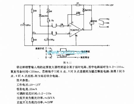
The operational amplifier of dainton tube input terminal is especially suitable for delay circuit. In figure, the circuit is 0.2~100s delay, repeat preparation time < 250ms. If the terminals 1 with A point, 2 with B connection, it is a delay circuit; If the terminals 1 withB point, 2 withA connection, it is a delay suck close circuit. (View)
View full Circuit Diagram | Comments | Reading(754)
three eliminate noise circuit
Published:2011/3/23 21:40:00 Author:Jessie | Keyword: eliminate noise
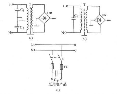
As shown in figure a, anti-disturbance measures which electronic products commonly used,is accessed two side implement road capacitance to the side on earth (cabinet) of power transformer. When C1 and C2 choose small capacity, only affect to thepulses which are very steep andvery narrow. If want to overcome the interference of energy larger pulse, at least need to store its base wave, and filter outthe harmonic three times, so C1 and C2 should be taken a little big. But this will bring danger.
(View)
View full Circuit Diagram | Comments | Reading(539)
160-185℃ temperature regulator circuit
Published:2011/4/17 23:01:00 Author:Nicole | Keyword: temperature regulator

This circuit adopts thermal resistor K18. It has large surface and it is propitious to fix, it also can drive large load, it is always made into clavate and fixed in sensor housing. It is connected into bridge structure, and the temperature given value is adjusted by potentiometer R1, the output circuit is controlled by relay.
The main technical data: the work voltage: 30V(-15~+10%); the adjustable temperature: 160~185℃; the allowable environmental temperature: 0~70℃; the temperature error(environmental temperature is in the range of 20~70℃): 0.5℃; the temperature difference between relay turns on and off: 1℃.
(View)
View full Circuit Diagram | Comments | Reading(595)
The person and equipment safe protection solid sensing switch
Published:2011/3/29 3:16:00 Author:Jessie | Keyword: safe protection, solid sensing
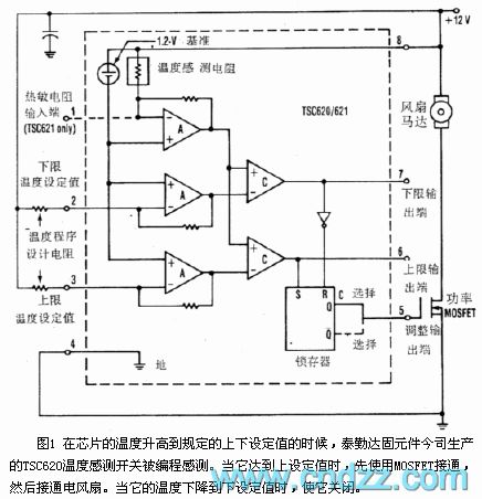
When the temperature of the chipincreases to theset value, Teledye is programming sensed by TSC620 temperature sensor switches. When it reaches the high set value, MOSFET connected, then electric fan is connected. When it's temperature reaches the low set value, it closed. Access a 90kΩ to 200kΩ resistancebewteen each program design input terminaland thepower of High-low temperature set value determining. When the temperature rises, low limit output frist increases, then high output just become higher. When the chip's temperatureis downto below the program design value 2℃, limit outputs respective becomes low.
(View)
View full Circuit Diagram | Comments | Reading(532)
Liquid electronic constant temperature box circuit
Published:2011/3/24 2:55:00 Author:Jessie | Keyword: liquid, constant temperature box

The thermistor K273 can be used to monitor and adjust liquid's temperature, it is always dipped in liquid. Differential amplifiers constitute bridge circuit, the selecting principle of bridge arm's resistance is that, before through the temperature which adjusted by switch S, thermistors' voltage drop is higher than differential amplifiers shot resistance's voltage drop. So that transistor T1's base is connected, T2 disconnected, relay release. Its closed contact r1 connects the heating element. Once the heating element temperature reaches the setting temperature, Differential amplifiers change, stop heating.
(View)
View full Circuit Diagram | Comments | Reading(639)
Three phases of phase lack protection circuit
Published:2011/3/27 22:45:00 Author:Jessie | Keyword: Three phases, phase lack protection
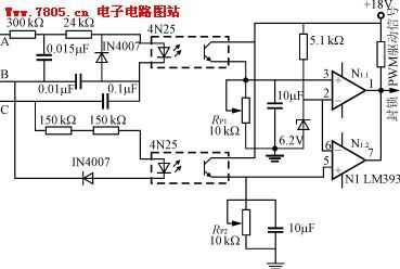
This is a kind of protection circuit used for three-phase three-wirepower phase lack, A, B and C lack any phase, light-coupler output level is lower than comparator's reversed-phase input terminal's benchmark voltage, comparator output low level, blockade PWM drive signal, andcut offpower. Comparator input polarity fluctuant, also can use a high level blockade PWM signal. This phase lack protection circuit uses high light-coupler isolation, safe and reliable, RP2, RP1 used to adjust phase lack protection movement threshold.
(View)
View full Circuit Diagram | Comments | Reading(2418)
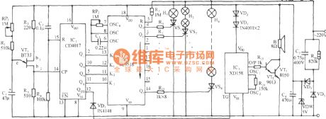
Flash light control circuit composed of 556、CD4017
Published:2011/3/24 4:39:00 Author:may | Keyword: Flash light control
Flash light control circuit composed of 556、CD4017 is shown in the following diagram:
(View)
View full Circuit Diagram | Comments | Reading(1184)
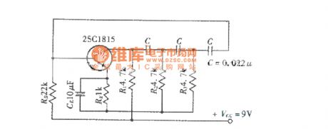
Phase shifting oscillating circuit examples circuit diagram
Published:2011/4/17 20:14:00 Author:Jessie | Keyword: Phase shifting oscillating, examples
View full Circuit Diagram | Comments | Reading(629)
MS51C61 falling, smooth flowing color lamp with firecrackers control circuit
Published:2011/4/15 22:28:00 Author:Nicole | Keyword: color lamp, firecrackers
View full Circuit Diagram | Comments | Reading(472)
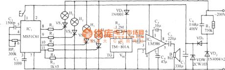
SK-12P program control varied flashing color lamp with disco music contorl circuit
Published:2011/4/15 22:24:00 Author:Nicole | Keyword: program control, flashing color lamp, disco music
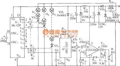
SK-12P is CMOS progaram control flashing special integrated circuit, it has seven-way output, it can drive seven-way SCR directly. Seven-way color lamp is cyclic changing with six kinds program control patterns chronological order, it is colorful. As shown, this is a program control varied flashing color lamp with disco music contorl circuit composed of SK-12P. (View)
View full Circuit Diagram | Comments | Reading(487)
SR63 multi-function festival color lamp with disco music contorl circuit
Published:2011/4/15 21:52:00 Author:Nicole | Keyword: festival color, disco music
View full Circuit Diagram | Comments | Reading(611)
SIC24P used in control AC color lamp application circuit
Published:2011/4/15 21:50:00 Author:Nicole | Keyword: AC color lamp
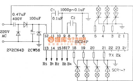
SIC24P is suit for fixed base, such as advertising, dance hall, stage and so on. Its output terminal can connect to thyristor and with AC 220V power supply to control the color lamp. (View)
View full Circuit Diagram | Comments | Reading(468)
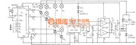
SE9201 multi-function program control flashing color lamp with disco music automatic control circuit
Published:2011/4/15 21:24:00 Author:Nicole | Keyword: program control, flashing color lamp, disco music, automatic control

View full Circuit Diagram | Comments | Reading(616)
SE9518 multi-function program control flashing color lamp with birdsong control circuit
Published:2011/4/15 21:21:00 Author:Nicole | Keyword: program control, flashing color lamp, birdsong
View full Circuit Diagram | Comments | Reading(479)
SE9518 multi-pattern program control color lamp with classical music automatic control circuit
Published:2011/4/15 21:19:00 Author:Nicole | Keyword: program control, color lamp, classical music, automatic control
View full Circuit Diagram | Comments | Reading(531)
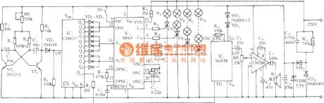
SE9518 multi-pattern program control neon light with musics automatic control circuit
Published:2011/4/15 21:00:00 Author:Nicole | Keyword: program control, neon light, music, automatic control
View full Circuit Diagram | Comments | Reading(468)
| Pages:292/312 At 20281282283284285286287288289290291292293294295296297298299300Under 20 |
Circuit Categories
power supply circuit
Amplifier Circuit
Basic Circuit
LED and Light Circuit
Sensor Circuit
Signal Processing
Electrical Equipment Circuit
Control Circuit
Remote Control Circuit
A/D-D/A Converter Circuit
Audio Circuit
Measuring and Test Circuit
Communication Circuit
Computer-Related Circuit
555 Circuit
Automotive Circuit
Repairing Circuit