
Index 285
Long Time Timing Circuit (LM307N/CA3094)
Published:2011/4/21 7:00:00 Author:Robert | Keyword: Long Time Timing
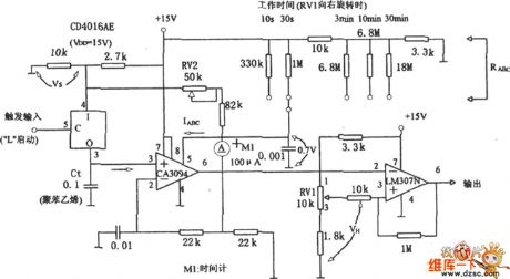
Long Time Timing Circuit (LM307N/CA3094) is shown below. This circuit uses the discharge of the controllable operational amplifier CA3094 to make a long time timing, generally change he VH via RV1, to achieve the goal of change the timing continuously.
(View)
View full Circuit Diagram | Comments | Reading(815)
Clock pulse coupling circuit
Published:2011/4/22 2:43:00 Author:Nicole | Keyword: Clock pulse
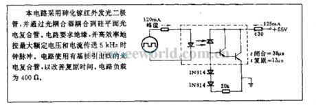
This cirucit adopts Gallium arsenide IR LED and it is coupled to silicon flat electro-optical composite pipe by optical coupler. The circuit requires insulation, and it can expeditiously transport 5kHz clock pulse according to the maximum rated voltage and current. The circuir uses the electro-optical composite pipe with base outgoing line to improve the recovery time. The circuit load is 400Ω. (View)
View full Circuit Diagram | Comments | Reading(516)
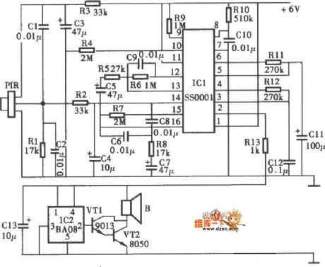
Infrared Ray Controlled Electronic Dog Circuit
Published:2011/4/21 8:32:00 Author:Christina | Keyword: Infrared Ray Controlled, Electronic Dog
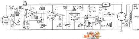
The Infrared Ray Controlled Electronic Dog Circuit is as shown:
(View)
View full Circuit Diagram | Comments | Reading(535)
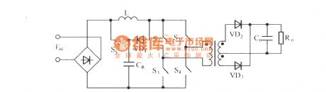
l3 parallel type single stage Boost PFC converter
Published:2011/4/22 3:10:00 Author:Nicole | Keyword: parallel type, PFC, converter
View full Circuit Diagram | Comments | Reading(463)
Skyworth TV Power Board Circuit
Published:2011/4/21 8:19:00 Author:Christina | Keyword: Skyworth TV, Power Board
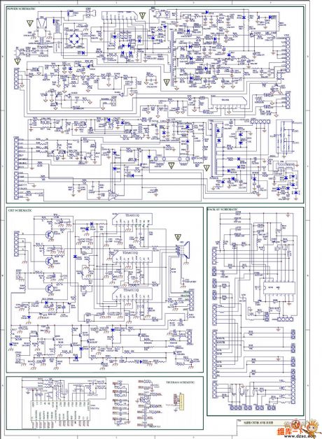
View full Circuit Diagram | Comments | Reading(2795)
Two-way Control Dimmable Corridor Lighting System Circuit
Published:2011/4/21 8:17:00 Author:Christina | Keyword: Two-way Control, Dimmable, Corridor Lighting System
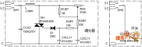
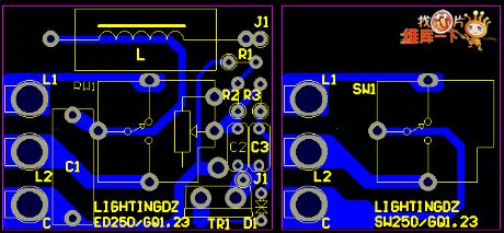
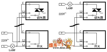
View full Circuit Diagram | Comments | Reading(1035)
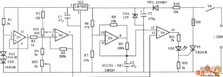
Electric Shock Warning Device Circuit
Published:2011/4/21 7:53:00 Author:Christina | Keyword: Electric Shock, Warning Device
The Electric Shock Warning Device Circuit is as shown:
(View)
View full Circuit Diagram | Comments | Reading(1087)
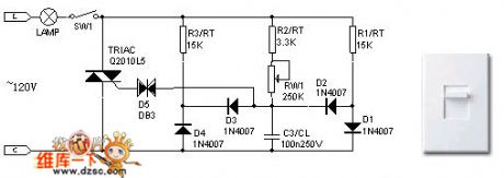
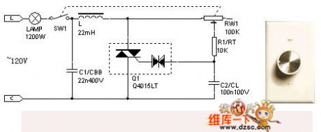
SCR Dimmer Circuit Of The 120V Incandescent Lamp
Published:2011/4/21 6:18:00 Author:Christina | Keyword: SCR Dimmer, 120V Incandescent Lamp
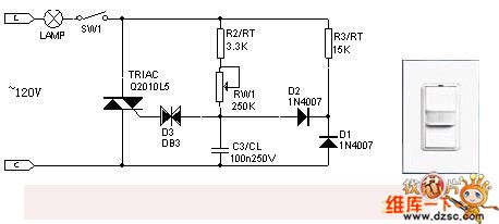
Typical 120v SCR Dimmer
Another Kind Of 120v SCR Dimmer
120v SCR Dimmer With The Composite Device (View)
View full Circuit Diagram | Comments | Reading(3986)
Timing flashing circuit using FET drive
Published:2011/4/20 21:46:00 Author:Nicole | Keyword: Timing flashing, FET drive

The circuit is as shown, it can form a timing control circuit of cycle light which only needs a few components. This circuit is composed of MOS time base circuit 7555, CMOS decimal counter (pulse distributor) 4017 and last stage VMOS power transistor. The power transistor can control the bulb with 2A maximum current. Resistance Rv between bulb and power supply +UB is used to limit connection current.
The frequency of time base circuit is adjusted by potentiometer RP(it is about 0.5~10Hz). Nine-stage circulation register passes clock input terminal then controlled by square wave output singal, to change each output terminal into high level. Because pin 11 is connected to reduction input terminal pin 15, so the coming tenth pulse will control the first light to turn on. (View)
View full Circuit Diagram | Comments | Reading(710)
Like polarity drive circuit
Published:2011/4/21 22:49:00 Author:Nicole | Keyword: like polarity
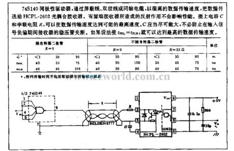
Using shield wire, twisted pair or coaxial cable, the 74S140 like polarity driver transports the data to HCPL-2602 optical coupling receiver with high data transmission speed. The reflex action produced by active terminal receiver has no influence on the performance. To connect capacitance C and in series with resistance R, it can make the data transmission speed reach the possible maximum speed. C should as large as possible, it is no need to prevent the regulator tube of receiver from turning off during the input singal negative bias. If tPHL=tPLH, then it will obtain the maximum data transmission speed. (View)
View full Circuit Diagram | Comments | Reading(579)
On/off control circuit
Published:2011/4/22 1:15:00 Author:Nicole | Keyword: On/off control

CA3062 combined photodetector and power amplifier can produce on/off output by optical signal. The output transistor of IC should be saturated or closed, prevent the temperature from rising. When the light of IR LED falls on the optical input terminal of IC, complementary output can select the load which is normal open or normal off. After blocking the light path, it will produceopposite load situation. (View)
View full Circuit Diagram | Comments | Reading(577)
Digital control constant current source
Published:2011/4/22 0:22:00 Author:Nicole | Keyword: Digital control, constant current source
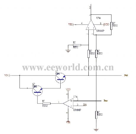
This digital control constant current source is designed for charging to storage battery. D/A converter outputs a voltage value to the in-phase terminal of below operational amplifier, the current I=Uad/ sampling resistance, two PORT is used to connect the +, - polar of storage battery. The above operational amplifier is connected into a amplifier circuit with 1/4 amplification. It is used to test the storage battery voltage. In figure, the two regulator are 3dd13 and 3dd15. (View)
View full Circuit Diagram | Comments | Reading(1833)
6~60s high precision timer
Published:2011/4/20 22:10:00 Author:Nicole | Keyword: 6~60s timer
6~60s high precision timer. The timing time range of this circuit is 6~60s. When turning on switch AN, relay J1 pull-in, capacitance C1 is changed by R1 and potentiometer KP. When the voltage on C1 reaches 2/3 of power supply, IC output state is reversed, to complete the timing process. The function of voltage stabilizing diode VW2: when power voltage changes, it can keep the voltage steady; VW1 is used to stabilize the capacitance charging voltage, it can improve the precision. The timing time of circuit is T=1.1(R1+KP)C1, to adjust KP will obtain any timing time between 6~60s. Voltage stabilizing diode VW1 can use 8V、1/2W,VW2 6V、1/2W. (View)
View full Circuit Diagram | Comments | Reading(560)
Home Thermostat Control Circuit
Published:2011/4/21 9:52:00 Author:Robert | Keyword: Home, Thermostat
Home Thermostat Control Circuit is shown below:
(View)
View full Circuit Diagram | Comments | Reading(747)
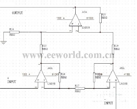
Voltage type drive circuit
Published:2011/4/21 3:51:00 Author:Nicole | Keyword: Voltage type drive

The drive circuit is as shown in figure (a), it is suitable for low frequency and low power drive, when the control singal Ui is high level, VT1 turns on, the switch tube(IGBT) controlled by output voltage Uo turns on too; when the control singal Ui is low level, VT2 turns on, the switch tube(IGBT) controlled by output voltage Uo turns off. The drive circuit is as shown in figure (b), it adopts push pull circuit composed of FET, the working principle is the same as figure (a). The high frequency peak value drive current of this circuit can reach more than 10A, it is suitable for high power IGBT devices. (View)
View full Circuit Diagram | Comments | Reading(506)
(CD4017、RCM1) Radio Control Light Switch Circuit
Published:2011/4/21 2:21:00 Author:TaoXi | Keyword: Radio Control, Light Switch
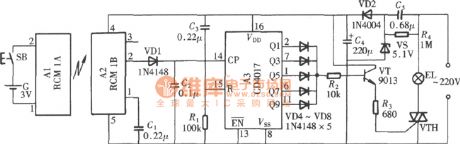
(CD4017、RCM1) Radio Control Light Switch Circuit
(View)
View full Circuit Diagram | Comments | Reading(1178)
Calendar clock circuit
Published:2011/4/21 1:33:00 Author:Nicole | Keyword: calendar, clock

FCM CT7001 clock chip is produced by Fairchild, it can make 7 paragraphs LED of 6 bits display 12h or 24h, and it also has the functions of 28/30/31 calendar and alarm clock. ③, ⑤, ⑩, (12) of SN75491 driver chip are connected to (11) by a 150Ω resistance. Usually, RL is 2.7kΩ, it can limit the LED current below 5mA. (View)
View full Circuit Diagram | Comments | Reading(1392)
Relay circuit with delay pull-in and delay release
Published:2011/4/19 6:19:00 Author:Nicole | Keyword: relay, delay pull-in, delay release
The circuit adopts single transistor circuit can achieve independent adjust delay pull-in and delay turn-off time, the circuit consists of a relay A with auxiliary contact a. After pressing switch S, capacitance C charges firstly, using potentiometer R2 can adjust pull-in time. After relay pull-in, auxiliary contact a connects resistance R5 and potentiometer R3 to transistor base, after switch S off, the ralay release time is determined by R3. (View)
View full Circuit Diagram | Comments | Reading(566)
Typical application circuit of audio synchronous color lamp control integrated circuit 5G052
Published:2011/4/18 10:06:00 Author:Nicole | Keyword: audio, color lamp
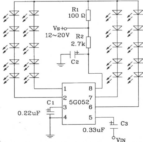
The sequence of 5G052 four-way output is A, B, C, D, the lowest work voltage VDD is 5V, but when the VDD declines, LED fluorescence change rate will rise, compared to power supply, the oscillation frequency fosc is unstable. In figure, the range of oscillation frequency is decided by C1, that is the variation range of fluorescence rate. If C1 increases, the parallel connecting resistance on C1 will improve the rate. C2 is power decoupling capacitor. R1 is LED current resistance. R2 is power supply current limiting. (View)
View full Circuit Diagram | Comments | Reading(522)
25Ω loundspeaker overload protection circuit
Published:2011/4/20 22:35:00 Author:Nicole | Keyword: 25Ω loundspeaker, overload protection
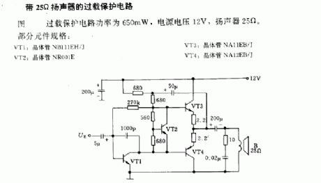
In figure, the overload protection circuit power is 650mW, the power voltage is 12V, the loundspeaker is 25Ω.
Some components' standard: VT1: transistor NB111EH/J; VT2: transistor NR001E; VT3: transistor NA11EB/J; VT4: transistor NA12EB/J. (View)
View full Circuit Diagram | Comments | Reading(552)
| Pages:285/312 At 20281282283284285286287288289290291292293294295296297298299300Under 20 |
Circuit Categories
power supply circuit
Amplifier Circuit
Basic Circuit
LED and Light Circuit
Sensor Circuit
Signal Processing
Electrical Equipment Circuit
Control Circuit
Remote Control Circuit
A/D-D/A Converter Circuit
Audio Circuit
Measuring and Test Circuit
Communication Circuit
Computer-Related Circuit
555 Circuit
Automotive Circuit
Repairing Circuit