
Circuit Diagram
Index 1464
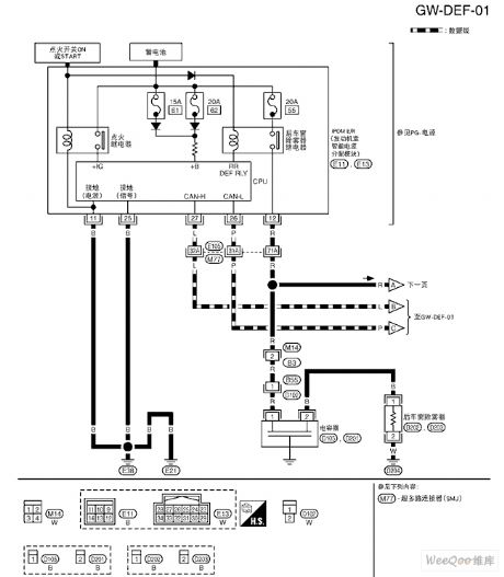
The power ground connection, fault indicator and data connector circuit of the 2.0L(L34) engines
Published:2011/7/20 3:54:00 Author:Borg | Keyword: power ground connection, fault indicator, data connector
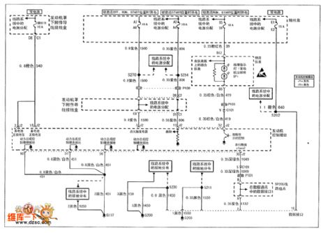
figure 1. The power ground connection, fault indicator and data connector circuit of the 2.0L(L34) engines of Shanghai GM Buick-Regal
(View)
View full Circuit Diagram | Comments | Reading(585)
The camshaft position, crank axle and igniting coil circuit of 2.0L(L34) engine
Published:2011/7/20 3:49:00 Author:Borg | Keyword: camshaft position, crank axle, igniting coil
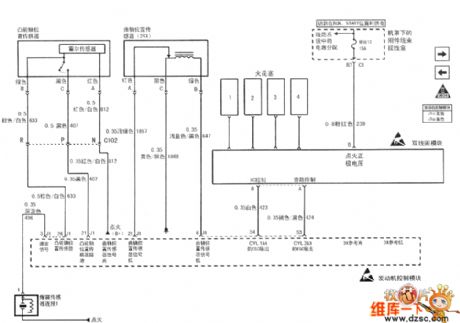
figure1. The camshaft position, crank axle and igniting coil circuit of 2.0L(L34) engine of Shanghai GM Buick-Regal (View)
View full Circuit Diagram | Comments | Reading(508)
The 2.0 L(L34)engine cooling and idle speed air temperature sensor circuit
Published:2011/7/20 3:46:00 Author:Borg | Keyword: idle speed, air temperature sensor
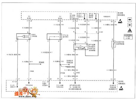
Figure 1. The 2.0 L(L34)engine circuit of Shanghai GM Buick-Regal--air-conditioning pressure sensor, throttle position sensor, admission MAP sensor, engine cooling temperature sensor and idling speed air temperature sensor (View)
View full Circuit Diagram | Comments | Reading(473)
The 2.0 L(L34)engine evaporation emitting circuit
Published:2011/7/20 3:41:00 Author:Borg | Keyword: evaporation emitting
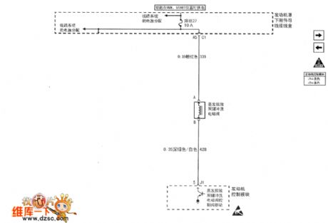
Figure 1. The 2.0 L(L34)engine evaporation emitting circuit of Shanghai GM Buick-Regal (View)
View full Circuit Diagram | Comments | Reading(631)
The 2.0L(L34) engine idle speed air control, oil position switch and pressure display circuit
Published:2011/7/20 3:38:00 Author:Borg | Keyword: idle speed, oil position switch
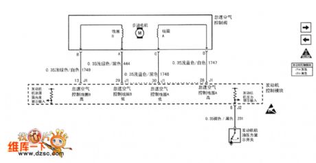
Figure1 The 2.0L(L34) engine idle speed air control, oil position switch and pressure display circuit of Shanghai GM Buick-Regal
(View)
View full Circuit Diagram | Comments | Reading(574)
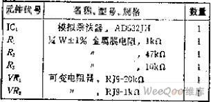
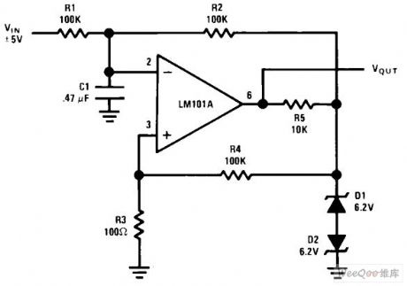
The division circuit for ratio calculation
Published:2011/7/14 23:04:00 Author:Fiona | Keyword: ratio calculation
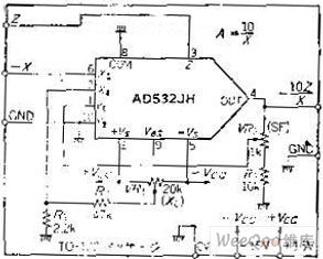
Circuit function
This circuit is the division circuit that the input signal Z is divided by X. Besides operating EO = 10Z / (-X) and calculating the ratio or percentage,it also can be used as AGC amplifier (A=1/X) which inputs control voltage from the X side. But it can't do large-scale operations. If the input X as the denominator turns smaller, 1 / X will increase,.When X = 0, the gain is infinite, so for division, the range is limited.
Circuit work
If the IC is used as a multiplication, the output voltage feedbacks to the Y input, does the 1 / X calculation, and then multiplies by Z. Because of adding a multiplication unit in the OP amplifier feedback loop, the X input turns smaller so that the circuit would become unstable. and the X values are different, closed-loop frequency characteristics will change because of X's different values. Pay attention to use it.
Z-ended input signal has been inverted in the output, the X input only can use the negative voltage . When X = 10V,the circuit uses VR2 to adjust scaling factor to make A = 1. It also can use VR2 to do disorders adjustment of dynamic range of the division circuit.After reducing the variable range, in order to facilitate adjustment, it addsvoltage divider circuit composed of the R1, R2. Input 1V from Z,input 1V from X, adjust VR1 to make the output to be -10V (A =- 10).when Z = 0.1V, X =- 0.1V,it also can get 10V output, but it can not guarantee the accuracy and stability Degrees. In addition, the frequency response changes with the value which is inputed from X.This point also should be noted. (View)
View full Circuit Diagram | Comments | Reading(661)
Telephone and facsimile apparatus protection circuit
Published:2011/7/11 2:51:00 Author:Fiona | Keyword: Telephone and facsimile apparatus, protection
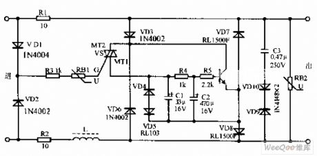
Telephone and facsimile apparatus protection circuit is shown as above,due to the exterior line often appears instantaneous high voltage to result in the damage of the telephone,the facsimile apparatus and so on.In view of this situation,this protection circuit can effectively prevent the damage of the telephone and the facsimile apparatus because of lightning stroke and line's accidental over-voltage.The circuit has no affect on telephone and facsimile apparatus completely. The transistor VD is 9013 and β = 65-115;Directional triode thyristor VS is SAC616;Resistor is the RJ type,nominal power is 0.25 ~ 0.5W on average.
(View)
View full Circuit Diagram | Comments | Reading(755)
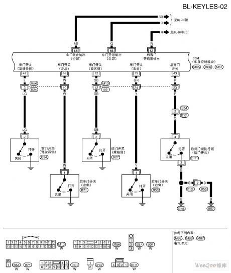
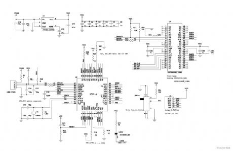
Tiida-BL remote control door system circuit Figure 1
Published:2011/7/14 23:18:00 Author:Fiona | Keyword: remote control, door system
View full Circuit Diagram | Comments | Reading(828)
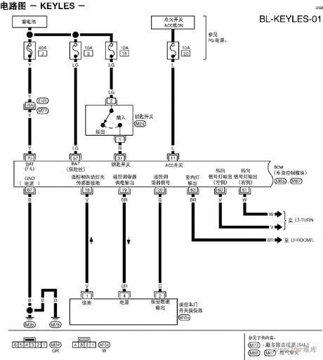
Tiida-BL remote control door system circuit
Published:2011/7/14 23:17:00 Author:Fiona | Keyword: remote control, door system
View full Circuit Diagram | Comments | Reading(989)
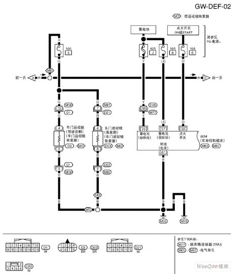
Tiida rear window demister circuit Figure 2
Published:2011/7/14 23:17:00 Author:Fiona | Keyword: rear window demister
View full Circuit Diagram | Comments | Reading(937)
Single stage PFC high brightness LED driver circuit achieving 700 mA current
Published:2011/7/19 8:49:00 Author:Fiona | Keyword: Single stage, high brightness, driver

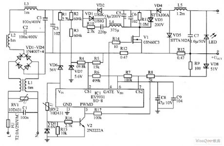
Figure is single-stage PFC LED driver power supply.With the increasing use of LED,especially extensive use of the offline type switch power supply composed of a sample circuit,it surely makes the power grid's power factor severely reduce and the power grid's reactive power consumption increase finally.Therefore increasing the switching power supply power factor and reducing harmonic current have become the development direction of LED lighting power supply in the future.This section describes using the falling rise and fall without transformer single-stage circuit,it can provide high conversion efficiency,it is low-cost,high reliability and high-power LED driver power supply.
(View)
View full Circuit Diagram | Comments | Reading(855)
Tiida rear window demister circuit Figure 1
Published:2011/7/14 23:18:00 Author:Fiona | Keyword: rear window demister
View full Circuit Diagram | Comments | Reading(1261)
relay drive circuit on low power supply voltage
Published:2011/7/14 23:16:00 Author:Fiona | Keyword: relay drive, low power supply voltage
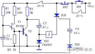
V1 is unijunction transistor BT33C,it composes the relaxation oscillator with R1, R2, R3 and C1,SCR is one-way controlled silicon,when press the start button AN1,the circuit is energized,because the SCR has no trigger voltage,the circuit is not conducted,the relay J doesn't move,the power charges the capacitor C2 to close to supply voltage through R4 and VD1(Vcc-VD1 drops).Meanwhile,the power R1 charges the capacitor C1. After a few seconds,the C1's voltage is charged to close to the trigger voltage of V1, C1 discharges immediately through V1 and forms a positive pulse on the R3, this pulse is all the way added to the V2 base to make the V2 be quickly saturated conducted,V2 collector namely capacitance C2 positive closes to ground.
(View)
View full Circuit Diagram | Comments | Reading(1255)
Pulse width modulator circuit
Published:2011/7/20 0:45:00 Author:Fiona | Keyword: Pulse width, modulator
View full Circuit Diagram | Comments | Reading(720)
The making circuit of crystal oscillator 80mW F.M. transmitter
Published:2011/7/20 0:44:00 Author:Fiona | Keyword: crystal oscillator, F.M. transmitter
Crystal oscillator 80mW F.M. transmitter's making circuit is shown as above:
(View)
View full Circuit Diagram | Comments | Reading(2034)
Low pass active filter circuit
Published:2011/7/20 0:43:00 Author:Fiona | Keyword: Low pass, active filter

Low pass active filter circuit is shown as above:
(View)
View full Circuit Diagram | Comments | Reading(786)
High pass active filter circuit
Published:2011/7/20 0:43:00 Author:Fiona | Keyword: High pass, active filter
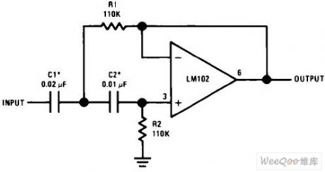
High pass active filter circuit is shown as above:
(View)
View full Circuit Diagram | Comments | Reading(912)
Multiplier of capacitor circuit
Published:2011/7/20 0:42:00 Author:Fiona | Keyword: capacitor, multiplier

Capacitor's multiplier circuit is shown as above:
(View)
View full Circuit Diagram | Comments | Reading(1384)
Voltage-stabilizing circuit having portable compact silicon regulator
Published:2011/7/20 0:42:00 Author:Fiona | Keyword: portable compact silicon regulator, Voltage-stabilizing
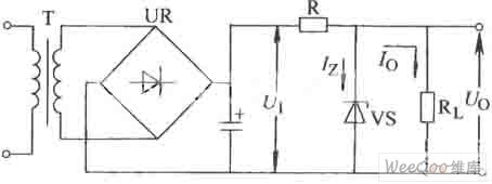
Voltage-stabilizing circuit having portable compact silicon regulator is shown as above:
(View)
View full Circuit Diagram | Comments | Reading(585)
±15V,5V three kinds of output regulated power supply circuit
Published:2011/7/20 0:41:00 Author:Fiona | Keyword: three kinds of output, regulated power supply
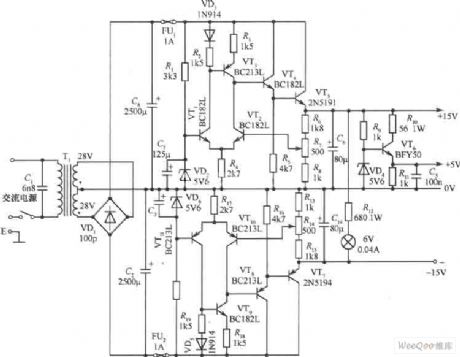
±15V,5V three kinds of output regulated power supply circuit is shown as above: (View)
View full Circuit Diagram | Comments | Reading(825)
| Pages:1464/2234 At 2014611462146314641465146614671468146914701471147214731474147514761477147814791480Under 20 |
Circuit Categories
power supply circuit
Amplifier Circuit
Basic Circuit
LED and Light Circuit
Sensor Circuit
Signal Processing
Electrical Equipment Circuit
Control Circuit
Remote Control Circuit
A/D-D/A Converter Circuit
Audio Circuit
Measuring and Test Circuit
Communication Circuit
Computer-Related Circuit
555 Circuit
Automotive Circuit
Repairing Circuit