
Circuit Diagram
Index 1460
The car burglarproof alarm (3)
Published:2011/7/23 20:53:00 Author:qqtang | Keyword: burglarproof alarm
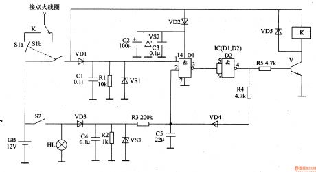
Here is to introduce a car burglarproof alarm which is installed in a hidden place, and it is used to confuse the thief, when the thief is stealing the motor, the motor seems to be ignited but doesn't move, finally, the motor can be ridden away, so the thief have to give up.The working principle of the circuit The car burglarproof alarm circuit consists of resistors R1-R5, capacitors C1-C5, diodes VD1-VD5, regulated diodes VS1-VS3, the transistor V, NAND integrated IC(D1 and D2) and relay K, see as figure 7-69.
(View)
View full Circuit Diagram | Comments | Reading(491)
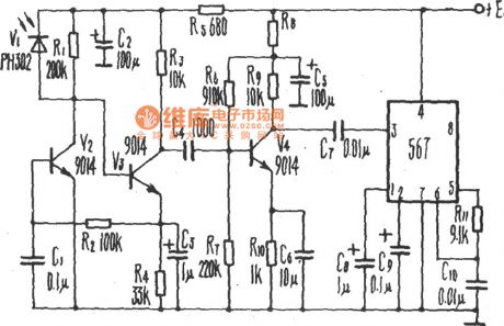
Electric Fan Infrared Sensor(567) Circuit
Published:2011/7/21 0:42:00 Author:Sue | Keyword: Electric Fan, Infrared Sensor
View full Circuit Diagram | Comments | Reading(997)
Domestic Appliance Infrared Remote Control Receiving Circuit
Published:2011/7/20 20:26:00 Author:Sue | Keyword: Domestic Appliance, Infrared Remote Control, Receiving
View full Circuit Diagram | Comments | Reading(493)
Long Time Delay Sound Control Light Switch Circuit Composed of CD4011
Published:2011/7/23 7:09:00 Author:Sue | Keyword: Long Time Delay, Sound Control, Light Switch
The long time delay sound control light switch shown in the picture has the longest delay time of 1h. It is suitable for primary and secondary school students tohave time control when they are doing the homework. Then students will have arest after they have studied for an hour. This can improve their learning efficiency. The picture shows the circuit, which consists of acoustic sensor, monostable delay circuit, relay, drive circuit and power circuit.
(View)
View full Circuit Diagram | Comments | Reading(824)
The motor burglarproof alarm (1)
Published:2011/7/23 20:18:00 Author:qqtang | Keyword: burglarproof alarm
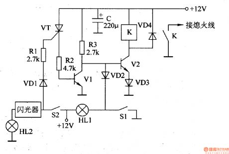
Here is to introduce a motor burglarproof alarm which can make the motor normally ignite when it is at the neutral gear, and put out when it is put into gear. The thief would think the motor is malfunctioning and leaves the motor.The working principle of the circuit The motor alarm circuit consists of the transistors V1 and V2, transistor VT, diodes VD1-VD4, relay K, resistors R1-R3 and capacitor C, see as figure 7-70.
(View)
View full Circuit Diagram | Comments | Reading(476)
The motor burglarproof alarm (2)
Published:2011/7/23 20:24:00 Author:qqtang | Keyword: burglarproof alarm

Here is to introduce the motor burglarproof alarm which adopts 2 relays as the burglarproof control part. When the thief ignite the engine with the skeleton key, just putting into gear will make the motor flameout, so the thief would think the motor is malfunctioning and leaves the motor.The working principle of the circuit The motor alarm circuit consists of the relays K1 and K2, control key S3, neutral switch S1, igniting switch S2 and so on, figure 7-71.
(View)
View full Circuit Diagram | Comments | Reading(480)
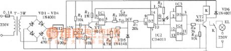
Bathroom Gating Light Exhaust Switch Circuit Composed of CD4001
Published:2011/7/27 5:39:00 Author:Sue | Keyword: Bathroom, Gating, Light Exhaust Switch
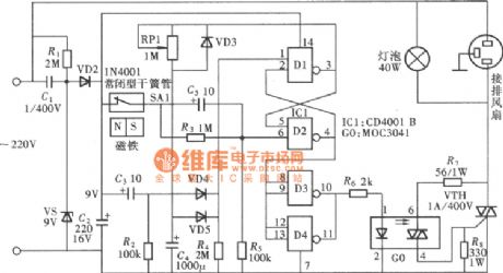
The control circuit uses gating technology. When someone comes in the room, the gating switch will start the light and exhaust fan automatically which will stop working automatically when it reaches the delay time. It is very convenient and the picture shows the circuit. The circuit uses one 412 input terminal or NOT GATE CD4001, two gates D1,D2 of which will compose one no triggered monostable delay circuit. Its delay time is decided by RP1's resistance value and C4's capacitance. The other two gates D3,D4 are connected and will be used as phase inverter and amplifier. (View)
View full Circuit Diagram | Comments | Reading(2525)
The motor burglarproof alarm (3)
Published:2011/7/23 20:30:00 Author:qqtang | Keyword: burglarproof alarm
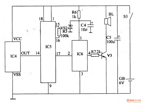
The working principle of the circuit
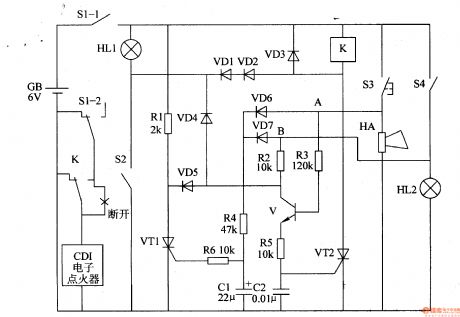
The motor alarm circuit consists of the diodes VD1-VD7, transistor V, thyristors VT1 and VT2, resistor R1-R6, capacitors C1 and C2, relay K, see as figure 7-72.
S1(S1-1, S1-2) is the motor lock switch, S2 is the neutral switch, S3 is the electric loudspeaker key, S4 is the brake switch. HL1 is the neutral gear indicator, HL2 is the brake lamp. GB is the motor battery. (View)
View full Circuit Diagram | Comments | Reading(489)
The car engine tachometer (1)
Published:2011/7/23 8:31:00 Author:qqtang | Keyword: engine tachometer
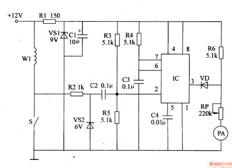
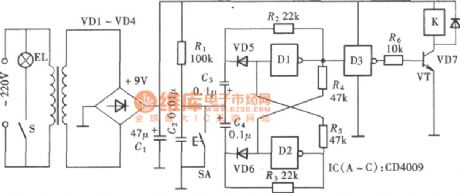
The working principle of the circuit The car engine tachometer consists of the 9V regulator circuit, single steady trigger circuit and current indicating circuit, see as figure 7-73.
The +9V voltage stabilizing circuit consists of the resistor R1, regulator diode VS1 and filter capacitor C1. The single steady trigger consists of the time-based integrated circuit IC, resistors R2-R5, capacitors C2-C4 and regulated diode VS2. The current indicating circuit consists of the diode VD, resistor R6, potentiometer RP and ampere meter PA. (View)
View full Circuit Diagram | Comments | Reading(2394)
The car engine tachometer (2)
Published:2011/7/23 8:40:00 Author:qqtang | Keyword: engine tachometer

The working principle of the circuit The car engine tachometer consists of the relaxation oscillator, integrating circuit, comparing amplifier and ampere meter drive circuit, see as figure 7-74.
The relaxation oscillator circuit consists of the resistors R1-R3, capacitor C1 and single knot transistor VU. The integrating circuit consists of the capacitor C3 and resistors (R4, R5). The comparing amplifier consists of the op-amp integrated circuit IC, resistors R6-R10, capacitor C2, diodes VD1-VD3 and so on. (View)
View full Circuit Diagram | Comments | Reading(926)
The LED car voltmeter (1)
Published:2011/7/23 20:00:00 Author:qqtang | Keyword: car voltmeter
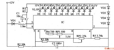
Here is to introduce the LED car voltmeter which is made of the LM3914 display drive integrated circuit and LED, the display voltage range is 10.5V-15v, it can be used vehicles of 12V battery.The working principle of the circuit The LED car voltmeter consists of the display drive integrated circuit IC, point/line display mode selection switch S, resistors R1-R5, potentiometers of RP1 and RP2, diodes VD1-VD5, capacitors of C1 and C2, LED VL1-VL10, see as figure 7-75.
(View)
View full Circuit Diagram | Comments | Reading(3217)
The LED car voltmeter (2)
Published:2011/7/23 20:04:00 Author:qqtang | Keyword: car voltmeter
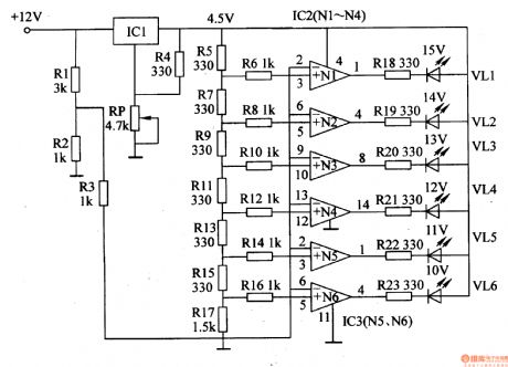
Here is to introduce the LED car voltmeter which is made of the op-amp LM312 and LED, it can display 6 gears of voltages, 10-15V, each gear is 1V.The working principle of the circuit The LED car voltmeter consists of the regulator circuit, Vref circuit, sampling voltage circuit and LED display drive circuit,see as figure 7-76.
The regulator circuit consists of the 3-terminal regulator circuit IC, potentiometer RP and resistor R4.
(View)
View full Circuit Diagram | Comments | Reading(4413)
The LED car voltmeter (3)
Published:2011/7/23 20:12:00 Author:qqtang | Keyword: car voltmeter
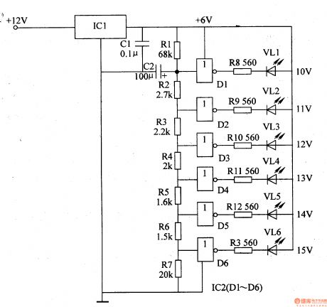
The working principle of the circuit The LED car voltmeter consists of the filter circuit, voltage distribution filter circuit, voltage amplifier circuit and LED display circuit, see as figure 7-77.
The regulator filter circuit consists of the 3-terminal IC1 and filter capacitor C1.The voltage distribution filter circuit consists of the resistors R1-R7 and capacitor C2.The voltage amplifier circuit consists of the 6 NOR gate circuitS IC2 (D1-D6).The LED display circuit consists of the LED vl1-vl6 and resistors R8-R13. (View)
View full Circuit Diagram | Comments | Reading(4363)
The automobile burglarproof alarm (1)
Published:2011/7/23 3:19:00 Author:qqtang | Keyword: burglarproof alarm
The working principle of the circuit The trigger alarm emitter circuit consists of the electric switch circuit, regulated filter circuit and encoding wireless emitter circuit, see as figure 7-78.
The electric switch circuit consists of the burglar switch S2, thyristor VT, transistors of V1 and V2, diodes of VD1 and VD2, resistors R1-R3, capacitors of C1 and C2, regulated diode VS1 and so on. The regulated filter circuit consists of the 3-terminal regulator IC1 and filter capacitor C3 (View)
View full Circuit Diagram | Comments | Reading(667)
The car burglarproof alarm (1)
Published:2011/7/23 20:38:00 Author:qqtang | Keyword: burglarproof alarm
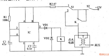
The working principle of the circuit The car burglarproof alarm circuit consists of the time-based integrated circuit IC, resistors R1 and R2, capacitors C1 and C2, diodes VD1 and VD2, relay K and burglarproof switch S1, see as figure 7-67.
Usually, the driver puts the hidden burglarproof switch at the point of 2 , the single steady time circuit consisting of IC, R1, R2, Cl and C2 does not work, the car can start and run normally. (View)
View full Circuit Diagram | Comments | Reading(538)
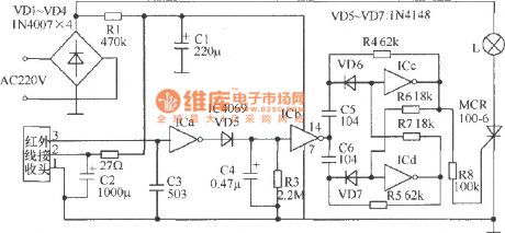
Touch Bathroom Exhaust Fan Time Delay Switch Circuit Composed of CD4069
Published:2011/7/27 5:40:00 Author:Sue | Keyword: Touch, Bathroom Exhaust Fan, Time Delay Switch
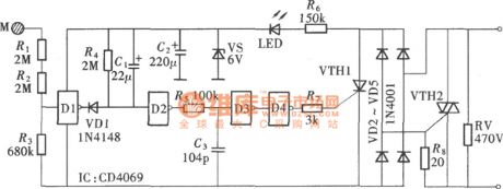
In the picture, the touch exhaust fan time delay switch consists of only one CD4069 and thyristor. It has simple structure and low production cost, and is affordable. The circuit is shown in the picture. The circuit structure is very simple. It connects CD4069's four phase inverters in series and time delay circuit R,C are added into it. The input terminal is connected to touch film M through high-value resistor R1,R2, and D4's output terminal is connected to the thyristor's trigger terminal. (View)
View full Circuit Diagram | Comments | Reading(2125)
The storage battery voltage monitor (4)
Published:2011/7/23 21:38:00 Author:qqtang | Keyword: storage battery, voltage monitor
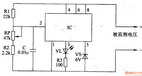
The working principle of the circuitThe battery voltage monitor circuit consists of resistors R1-R3, potentiometer RP, capacitor C, LED VL, regulated diode VS and time-based integrated circuit IC, see as figure 7-51.
The voltage of the battery GB is higher than 10.2V, the 3-pin of IC is outputing a low LEV, VL is not glowing; when the voltage of the battery GB is lower than 10.2V, the 3-pin of IC is outputting a high LEV, VL is glowing, the indicating batter voltage is too low. (View)
View full Circuit Diagram | Comments | Reading(544)
The battery charge/discharge monitor
Published:2011/7/23 21:29:00 Author:qqtang | Keyword: charge/discharge monitor
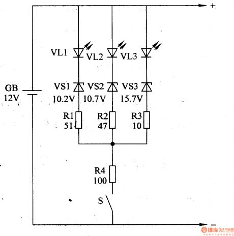
Here is to introduce a battery charge/discharge monitor which indicates the battery charge/discharge state with the 3R LED VL. The circuit is simple.The working principle of the circuitThe battery charge/discharge monitor circuits consist of the resistors R1-R4, LED VLl-VL3, regulator diodes VSl-VS3 and switch S, see as figure 7-52.
When charging, the voltage of VLl-VL3 on the battery terminal is rising to 16.2V, the indicators are all glowing, which means the battery is full and the charge current should be cut off or reduced. (View)
View full Circuit Diagram | Comments | Reading(1177)
Touch Lamp Switch Circuit Composed of CD4009
Published:2011/7/21 20:05:00 Author:Sue | Keyword: Touch, Lamp Switch
The touch lamp switch can turn on or turn off the lamp by being touched by any body part of people. For some certain occasions, this function is very meaningful. The picture shows how it is composed. The circuit uses only one hex inverter CD4069. Two gates D1,D2 of it compose a negative pulse bistable flip-flop. It uses the other gate D3 to compose an phase inverter. Then it uses a relay driving tube to drive a relay to achieve the lamp switch control. (View)
View full Circuit Diagram | Comments | Reading(1607)
Summing Integrator Circuit
Published:2011/7/21 1:08:00 Author:Sue | Keyword: Summing, Integrator
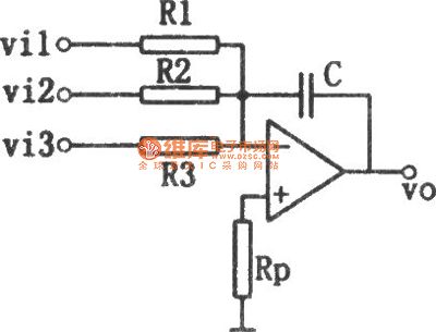
The picture shows the summing integrator circuit. It is named as summing integratorfor thereason thatthe circuit has many input return circuits.
Figure1 Summing Integrator Circuit (View)
View full Circuit Diagram | Comments | Reading(1509)
| Pages:1460/2234 At 2014411442144314441445144614471448144914501451145214531454145514561457145814591460Under 20 |
Circuit Categories
power supply circuit
Amplifier Circuit
Basic Circuit
LED and Light Circuit
Sensor Circuit
Signal Processing
Electrical Equipment Circuit
Control Circuit
Remote Control Circuit
A/D-D/A Converter Circuit
Audio Circuit
Measuring and Test Circuit
Communication Circuit
Computer-Related Circuit
555 Circuit
Automotive Circuit
Repairing Circuit