
Circuit Diagram
Index 1442
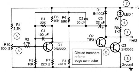
LAMP_SWITCHING_CIRCUIT
Published:2009/6/16 2:49:00 Author:May
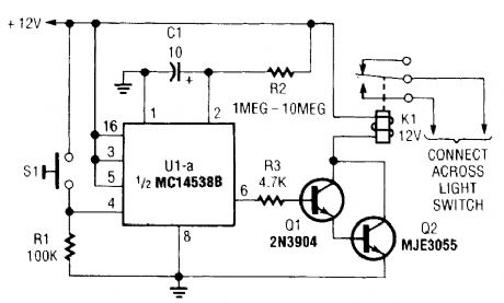
A normally open pushbutton switch (51) delivers a positive input pulse to pin 4 of U1, triggering the IC into action. The output of U1 at pin 6 supplies base-drive current to a Darlington pair comprised of Q1 and Q2, activating K1. A 10-μF capacitor and any resistor value of from 1 to 10 MΩ can be used as the timing components.To use the circuit on an auto's headlights, connect the relay's normally open contacts across the car's headlight switch and press S1 to extend the on time. In connecting the circuit to control an acoperated lamp, turn off the ac power and connect the relay contacts in parallel with the lamp's power switch contacts. (View)
View full Circuit Diagram | Comments | Reading(909)
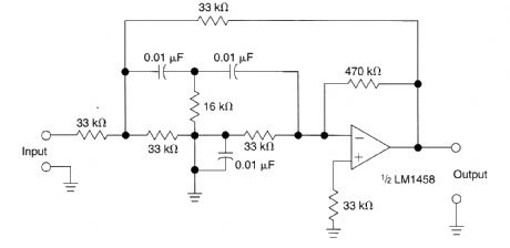
ACTIVE_SECOND_ORDER_BANDPASS_FILTER_FOR_SPEECH_RANGE
Published:2009/6/16 2:45:00 Author:May
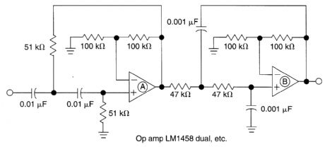
This filter circuit which uses LM1458 or similar op amp has a response of 300 Hz to 3.4 kHz with 12 dB/octave roll-off outside the pass band. Section A is the high-pass one, followed by Iow-pass sec-tion B. Values of either section can be scaled to alter the pass band. (View)
View full Circuit Diagram | Comments | Reading(1938)
AUDIO_NOTCH_FILTER_FOR_SHORTWAVE_RECEIVERS
Published:2009/6/16 2:45:00 Author:May
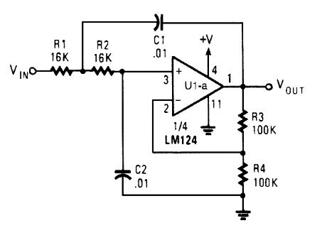
The notch filter can be added to just about any receiver to attenuate a single frequency by more Lhan 30 dB. This filter should be handy for reducing heterodynes and whistles. (View)
View full Circuit Diagram | Comments | Reading(1161)
BRAKE_AND_TURN_INDICATOR
Published:2009/6/16 2:43:00 Author:May
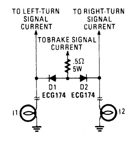
This might be a quick solution to getting the two-wire truck harness to support both turn and braking indications. (View)
View full Circuit Diagram | Comments | Reading(750)
HEADLIGHTS_ON_REMINDER
Published:2009/6/16 2:43:00 Author:May
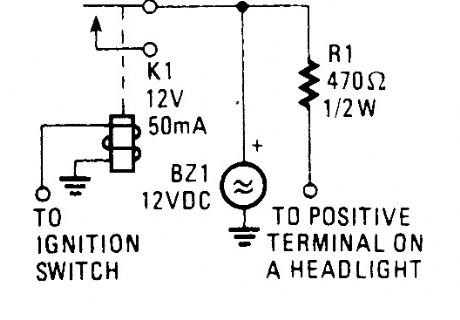
This circuit will sound alarm BZ1 if the ignition is turned off with the headlights on. (View)
View full Circuit Diagram | Comments | Reading(704)
ACTIVE_FOURTH_ORDER_LOW_PASS_FILTER
Published:2009/6/16 2:42:00 Author:May
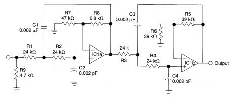
This circuit is a fourth-order low-pass filter with values for kHz. The values of R1,R2,C1 and C2, and R3, R4, C3 and C4 can be scaled for operation at other frequencies. Roll-off is 24 dB/octave. (View)
View full Circuit Diagram | Comments | Reading(1190)
ENGINE_BLOCK_HEATER_MINDER
Published:2009/6/16 2:42:00 Author:May
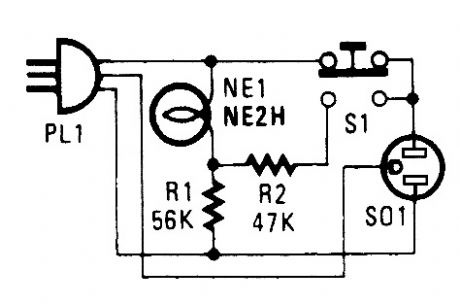
If you live in the frozen north, knowing your engine-block heater is working is a comfort. This device will let you know if yours is okay. Plug in PL1 to your power outlet. NE1 should light.Then, plug in the block heater. Depressing S1 should cause the indicator to get brighter. If not, your block heater might be open and inoperative. (View)
View full Circuit Diagram | Comments | Reading(773)
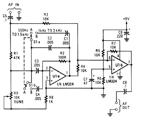
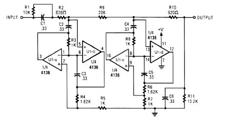
VARIABLE_BANDPASS_AUDIO_FILTER
Published:2009/6/16 2:41:00 Author:May
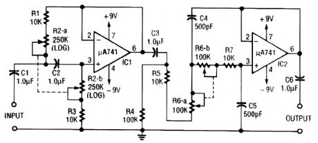
This circuit is a variable audio bandpass filter that has a low cutoff variable from about 25 Hz to 700 Hz and a high cutoff variable from 2.5 kHz to over 20 kHz. Rolloff is 12 dB/octave on both high and low ends. R2-a-b and RG-a-b are ganged potentiometers for setting lower and upper cutoff fre-quencies, respectively. (View)
View full Circuit Diagram | Comments | Reading(4257)
AUTOMOTIVE_AUDIBLE_TURN_INDICATOR
Published:2009/6/16 2:41:00 Author:May
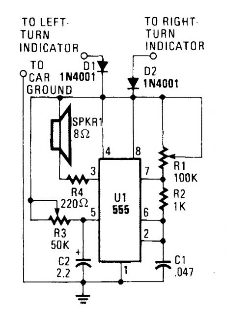
This little circuit should be useful to the hearing impaired. It produces a tone each time a dashboard turn indicator lights. The tone drops in frequency for as long as the indicator is lit. (View)
View full Circuit Diagram | Comments | Reading(588)
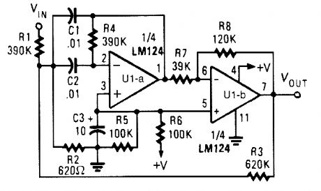
TWIN_T_NOTCH_FILTER_FOR_1_kHz
Published:2009/6/16 2:39:00 Author:May
The circuit shown uses a twin T notch filter and an amplifier. Used to remove unwanted frequency. (View)
View full Circuit Diagram | Comments | Reading(1360)
VARIABLE_Q_FILTER_FOR_400_Hz
Published:2009/6/16 2:39:00 Author:May
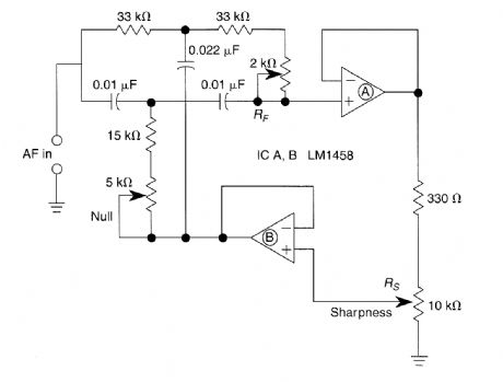
A bootstrapped twin T notch filter in this circuit can yield an effective Q of up to 10. RS adjusts the feedback, hence the Q. Values of C1 and C2 can be changed to alter the frequency. RF is a fine-tune null control. (View)
View full Circuit Diagram | Comments | Reading(1102)
FOUR_OUTPUT_FILTER
Published:2009/6/16 2:37:00 Author:May
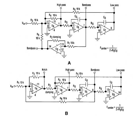
The classic state-variable (two-integrator) filter (see Fig. A) is famous for its insensitivity to device parameter tolerances, as well as its ability to provide three simultaneous separate outputs: high pass, bandpass, aind low pass. These advantages often offset the fact that a quad operational amplifier is needed to implernent the circuit.A modification of the classic scheme that applies the input voltage via amplifier U,, rather than UD provides a bandpass output with a fixed peak gain that doesn't depend on the Q of the filter. It was found by using that conftguration, a fourth notch-filter output can be obtained if R1=R6 (see Fig. B).If R1=R6=R12 the gains of both the notch and bandpass outputs are unity, regardless of the Q factor, as determined by R3, R1, R2, R4, R5, and R6. The resonant (or cutoff) frequency is given by ω -1/RO×CO Depending on the capacitor values and frequency ω, resistance RO might also share the same monolithic network for maximum space economy. As with the classic configuration, reso-nant frequency ω can be electrically controlled by switching resistors RO, or by using analog multi-pliers in series with the integrators. (View)
View full Circuit Diagram | Comments | Reading(758)
HEADLIGHT_FLASHER
Published:2009/6/16 2:35:00 Author:May
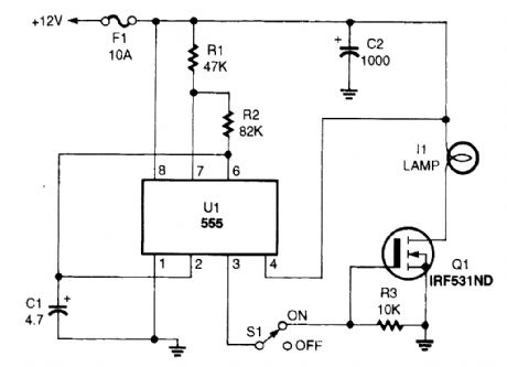
The headlight flasher is nothing more than a 555 oscillator/timer that's configured as an astable multivibrator (oscillator). Its input is used to drive the gate of an IRF53IND hexFET, which, in turn, acts like an on/off switch, turning the lamp on and off at the oscillating frequency (1 Hz). (View)
View full Circuit Diagram | Comments | Reading(2584)
AUTO_TURN_SIGNAL_REMINDER
Published:2009/6/16 2:35:00 Author:May
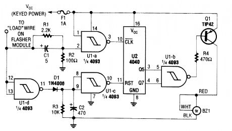
This circuit counts turn signal flashes. At the end of about 70 flashes, a chime sounds to remind the driver to turn off the turn signal. By using various taps on U2, the period can be changed if de-sired. BZ1 is a buzzer or chime module. (View)
View full Circuit Diagram | Comments | Reading(989)
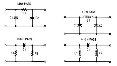
PASSIVE_PI_FILTER_CONFIGURATIONS
Published:2009/6/16 2:33:00 Author:May
View full Circuit Diagram | Comments | Reading(868)
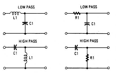
PASSIVE_L_FILTER_CONFIGURATIONS
Published:2009/6/16 2:32:00 Author:May
View full Circuit Diagram | Comments | Reading(808)
ACTIVE_LOW_PASS_RC_FILTER
Published:2009/6/16 2:32:00 Author:May
The circuit shown has a cutoff frequency at about 1 kHz. R1, R2, C1, and C2 can be scaled to change this to any other desired frequency. (View)
View full Circuit Diagram | Comments | Reading(1009)
BANDPASS_FILTER_1
Published:2009/6/16 2:32:00 Author:May
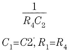
Appropriate center frequency of this circuit is:
(View)
View full Circuit Diagram | Comments | Reading(698)
BOOSTER_AMPLIFIER_FOR_CAR_STEREO_USE
Published:2009/6/16 2:31:00 Author:May

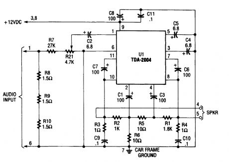
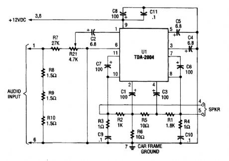
Only one channel of this circuit is shown. The other is practically a carbon copy.The input to the circuit, taken from your car radio's speaker output, is divided along two paths; in one path, a high-power divider network (consisting of R8 through R10) provides 4.5-Ω resistance to make the circuit's input impedance compatible with the output irrtpedance of the car radio. In the other path, the signal is fed to the input of U1 through resistor LR7, trimmer potentiometer R21, and capacitor C2. Together, R7 and R21 offer a minimum resistance of 27,000 Ω.Integrated circuit U1 (a TDA-2004 audio power amplifter) ampliftes the signal, which is then out-put at pins 8 and 10 and fed to the loudspeaker. Note: This amp is designed for use only with car radios whose speaker outputs are referenced to ground: do not use it with radios that have balanced outputs. (View)
View full Circuit Diagram | Comments | Reading(2211)
400_Hz_LOW_PASS_BUTTERWORTH_FILTER
Published:2009/6/16 2:30:00 Author:May
Designed for a 400-Hz cutoff frequency, the cutoff can be scaled by varying the element values proportionally to frequency (View)
View full Circuit Diagram | Comments | Reading(795)
| Pages:1442/2234 At 2014411442144314441445144614471448144914501451145214531454145514561457145814591460Under 20 |
Circuit Categories
power supply circuit
Amplifier Circuit
Basic Circuit
LED and Light Circuit
Sensor Circuit
Signal Processing
Electrical Equipment Circuit
Control Circuit
Remote Control Circuit
A/D-D/A Converter Circuit
Audio Circuit
Measuring and Test Circuit
Communication Circuit
Computer-Related Circuit
555 Circuit
Automotive Circuit
Repairing Circuit