
Circuit Diagram
Index 1459
Video Capture Circuit
Published:2011/7/20 7:26:00 Author:Sue | Keyword: Video Capture
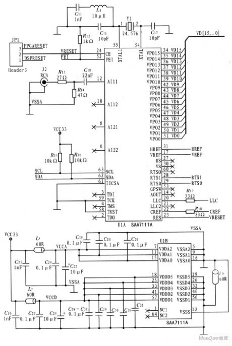
The video decoder this system uses is Philip company's high-performance video A/D converter SAA7111. The device is high-performance video input processor which is widely used in desktop video, multi-media, digital television, photo processing, visual telephone. It uses 3.3V CMOS circuit and highly integrated analog front end and digital video encoder which include two circuits of analog video processing channel, one clock generating circuit, one automatic clamp and gain control circuit, one multi system digital decoder, one brightness/contrast/saturation control circuit, and a color space matrix. (View)
View full Circuit Diagram | Comments | Reading(1760)
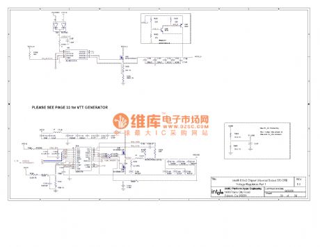
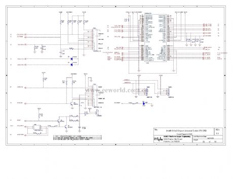
Computer motherboard circuit 810 2_34
Published:2011/7/26 21:32:00 Author:Ecco | Keyword: Computer motherboard
View full Circuit Diagram | Comments | Reading(511)
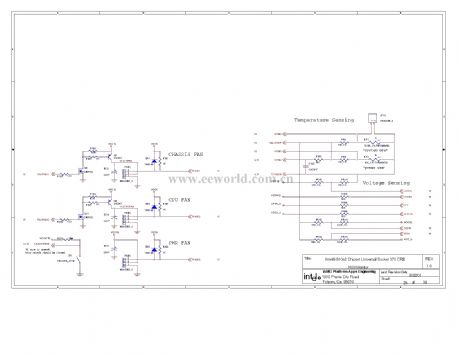
Computer motherboard circuit 810 2_33
Published:2011/7/26 21:46:00 Author:Ecco | Keyword: Computer motherboard
View full Circuit Diagram | Comments | Reading(517)
The industrial oil furnace controller (2)
Published:2011/7/23 2:42:00 Author:qqtang | Keyword: oil furnace controller
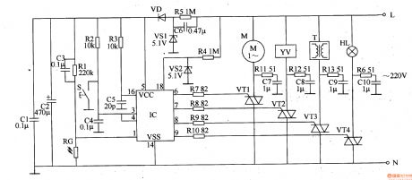
The working principle of the circuit The industrial oil furnace controller consists of the power supply circuit, detection/ignition control circuit and control executing circuit, see as figure 8-89.
The power supply circuit consists of the capacitor C6, releasing resistor R5, regulated diode VS1, rectifier diode VD and filter capacitors of C1 and C2. The detection/ignition control circuit consists of the resistor R1-R4, light sensitive resistor RG, capacitor C3-C5, reset key S, regulated diode VS2 and control integrated circuit IC. (View)
View full Circuit Diagram | Comments | Reading(819)
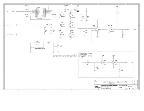
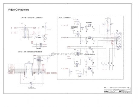
Computer motherboard circuit 810 2_32
Published:2011/7/26 21:46:00 Author:Ecco | Keyword: Computer motherboard
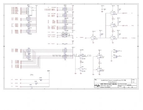
View full Circuit Diagram | Comments | Reading(565)
Bracing Wire Displacement Sensor
Published:2011/7/20 7:08:00 Author:Sue | Keyword: Bracing Wire, Displacement, Sensor
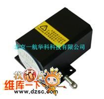
YHL-type displacement sensor will change machine displacement into measurable and electric signal of proportional linearity. When the object has displacement, we can pull the connected steel wire, then the wire will drive the sensor gear to rotate simultaneously with the sensor components. When the displacement is opposite, sensor's internal spring gyroscope will withdraw the coil automatically, and the tension force will remain unchanged during the process. Then electric signals which is directly proportional to the coil's displacement will be output.
The product is small-sized industrial product which is designed on the basis of vibration environment.
(View)
View full Circuit Diagram | Comments | Reading(550)
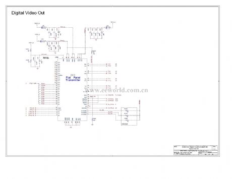
Computer motherboard circuit 810 2_31
Published:2011/7/26 21:45:00 Author:Ecco | Keyword: Computer motherboard
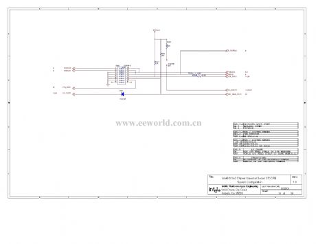
View full Circuit Diagram | Comments | Reading(475)
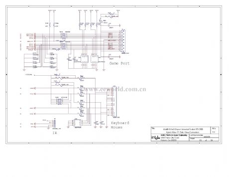
Computer motherboard circuit 810 2_30
Published:2011/7/26 21:45:00 Author:Ecco | Keyword: Computer motherboard
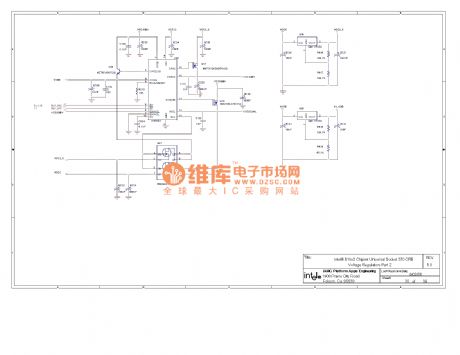
View full Circuit Diagram | Comments | Reading(500)
The car sound burglarproof alarm (2)
Published:2011/7/23 2:56:00 Author:qqtang | Keyword: burglarproof alarm
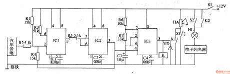
The working principle of the circuitThe car sound burglarproof alarm consists of the trigger control circuit and alarm circuit, see as figure 7-102.
The trigger control circuit consists of the time-based integrated circuits of IC1 and IC2, resistors R1-R5 and capacitors of C1 and C2.The alarm circuit consists of the time based integrated circuit IC3, resistors of R6 and R7, capacitor VD, relay K and the flash HL on the car, loudspeaker HA and so on. (View)
View full Circuit Diagram | Comments | Reading(610)
Computer motherboard circuit 810 2_29
Published:2011/7/26 21:44:00 Author:Ecco | Keyword: Computer motherboard
View full Circuit Diagram | Comments | Reading(513)
Computer motherboard circuit 810 2_28
Published:2011/7/26 21:58:00 Author:Ecco | Keyword: Computer motherboard
View full Circuit Diagram | Comments | Reading(511)
Computer motherboard circuit 810 2_27
Published:2011/7/26 21:58:00 Author:Ecco | Keyword: Computer motherboard
View full Circuit Diagram | Comments | Reading(537)
Computer motherboard circuit 810 2_26
Published:2011/7/26 21:57:00 Author:Ecco | Keyword: Computer motherboard
View full Circuit Diagram | Comments | Reading(523)
Fuel Injection System Circuit of Hyundai Sonata with V4 Cylinder Engine (10)
Published:2011/7/18 3:29:00 Author:Sue | Keyword: Fuel Injection, Hyundai Sonata, V4 Cylinder
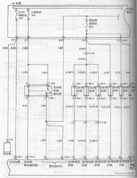
The picture shows the fuel injection system circuit of Hyundai Sonata with V4 cylinder engine. (View)
View full Circuit Diagram | Comments | Reading(844)
The automobile burglarproof alarm (2)
Published:2011/7/23 3:24:00 Author:qqtang | Keyword: burglarproof alarm
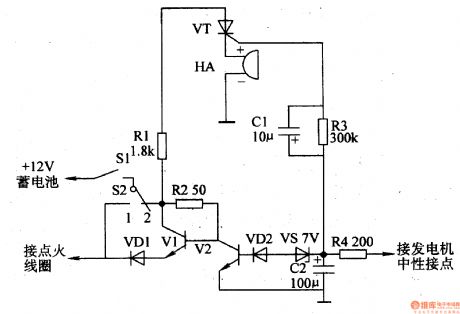
The working principle of the circuit The burglarproof alarm circuit consists of the burglarproof control circuit and trigger alarm circuit, see as figure 7-80.
The burglarproof control circuit consists of the car igniting switch S1, burglar switch S2, diodes of VD1 and VD2, transistor V1 and V2, resistor R2 and capacitor C2. The trigger alarm circuit consists of the resistors (R1, R3 and R4), capacitor C1, thyristor VT and buzzer HA. (View)
View full Circuit Diagram | Comments | Reading(520)
The car burglarproof alarm (2)
Published:2011/7/23 20:46:00 Author:qqtang | Keyword: burglarproof alarm
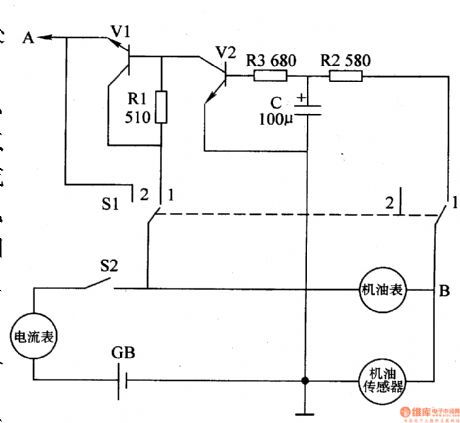
Here is to introduce a car burglarproof alarm which utilizes the pulse signal generated when the engine oil meter and the sensor are working, the circuit is simple, and it can be used in both petrol engine and diesel engine.The working principle of the circuit The car burglarproof alarm circuit consists of the transistors V1 and V2, resistors R1-R3, capacitor C and burglar switch S1 and so on, see as figure 7-68.
When the burglarproof switch is at the gear of 2 , the former circuit is working normally, the burglarproof circuit is not working. (View)
View full Circuit Diagram | Comments | Reading(600)
Computer motherboard circuit 810 2_25
Published:2011/7/26 21:57:00 Author:Ecco | Keyword: Computer motherboard
View full Circuit Diagram | Comments | Reading(580)
Computer motherboard circuit 810 2_24
Published:2011/7/26 21:56:00 Author:Ecco | Keyword: Computer motherboard
View full Circuit Diagram | Comments | Reading(535)
Computer motherboard circuit 810 2_23
Published:2011/7/26 21:55:00 Author:Ecco | Keyword: Computer motherboard
View full Circuit Diagram | Comments | Reading(518)
Frequency Shift Keying(FSK) Signal Generator Circuit
Published:2011/7/21 0:44:00 Author:Sue | Keyword: FSK, Signal Generator
View full Circuit Diagram | Comments | Reading(615)
| Pages:1459/2234 At 2014411442144314441445144614471448144914501451145214531454145514561457145814591460Under 20 |
Circuit Categories
power supply circuit
Amplifier Circuit
Basic Circuit
LED and Light Circuit
Sensor Circuit
Signal Processing
Electrical Equipment Circuit
Control Circuit
Remote Control Circuit
A/D-D/A Converter Circuit
Audio Circuit
Measuring and Test Circuit
Communication Circuit
Computer-Related Circuit
555 Circuit
Automotive Circuit
Repairing Circuit