
Circuit Diagram
Index 1453
The bicycle burglarproof alarm (1)
Published:2011/7/22 21:56:00 Author:qqtang | Keyword: burglarproof alarm
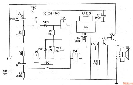
The working principle of the circuit The bicycle burglarproof alarm consists of the trigger control circuit and voice alarm circuit, see as figure 7-109.
The trigger control circuit consists of the sensor SQ, diodes VDl-VD4, resistors Rl-R6, capacitors of C1, C2, C4, NAND integrated circuit ICl(Dl-D4) and so on. The sound alarm circuit consists of the sound integrated circuit IC2, transistors V1 and V2, resistors R7-R8, capacitor C5, output transformer T and loudspeaker BL. (View)
View full Circuit Diagram | Comments | Reading(582)
The bicycle burglarproof alarm (2)
Published:2011/7/22 22:05:00 Author:qqtang | Keyword: burglarproof alarm
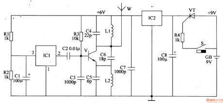
The working principle of the circuit The bicycle burglarproof alarm consists of the trigger control circuit, regulator filter circuit, music generator circuit and wireless emitting circuit, see as figure 7-110.
The trigger control circuit consists of the trigger switch S, resistor R4 and thyristor VT. The regulator filter circuit consists of the 3-terminal voltage regulator integrated circuit IC2 and resistors of C7 and C8. The music generator circuit consists of the resistors R1 and R2, capacitor C1 and 3-terminal music integrated circuit IC1. (View)
View full Circuit Diagram | Comments | Reading(619)
Multilevel parallel connection improved SNR amplifier circuit diagram
Published:2011/6/29 0:59:00 Author:Rebekka | Keyword: multilevel parallel connection, improved SNR amplifier
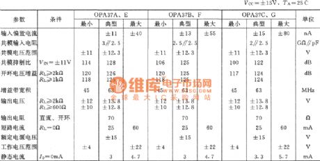
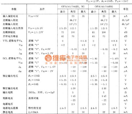
Theop-amp integrated the main parameters of the OPA37:
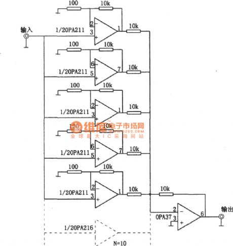
The input stage amplifier uses multistage parallel to improve the SNR of the amplifier circuit. This is because the input signal voltage is amplified by parallel multistage amplifier circuit and then passes the second amplifier peace. The total output voltage will be increased many times. This multiple is equal to the input stage parallel series. It is shown in figure and gives level l0 input shunt amplifier circuit for the first oder, and the second oder uses reverse phase peace circuit. If the input level is n level, the input signal output voltage will be improved for many times. (View)
View full Circuit Diagram | Comments | Reading(1118)
The electric air pressure switch
Published:2011/7/22 9:24:00 Author:qqtang | Keyword: air pressure switch
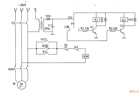
The working principle of the circuitThe electric air pressure switch circuit consists of the power supply circuit and pressure detecting control circuit, see as figure 8-129.
 The power supply circuit consists of the transformer T, rectifier diode VD1 and filter capacitor C.The pressure detection control circuit consists of the pressure meter P, resistors of R1 and R2, transistors of V1 and V2, relays of K1 and K2, diodes of VD2 and VD3. (View)
View full Circuit Diagram | Comments | Reading(2518)
Using encoding and decoding IC multi-channel remote control switch circuit diagram
Published:2011/5/8 5:24:00 Author:Rebekka | Keyword: Multi-channel remote control switch
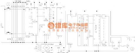
This article describes the NC multiple switch that composed of eight key remote control and receiver with eight relay. The device uses a high stability of dedicated wireless transceiver modules, and remote control encoder / decoder ICs with high security, remote control distance, performance, reliability and low static power consumption. You can use the remote control of the eight home appliances switch. CNC multi-channel remote control switch circuit is shown in figure 1. The remote control is composed of three integrated components. Circuit U1 (74LS148) is the 8-3 line of code integrated circuit, it can code the eight switch signals into BCD code output. U2 (VD5026) special code is the remote control integrated circuit. The IC has a total of 8-bit address code, 4-bit data code. This circuit uses the three data code only. The 8-bit address code can be combined freely. It means to connect the positive and negative power supply or the three encoding states composed of floating. There are 6561 kinds of different coding states to distinguish different devices. U3 (YG300U-S) is the wireless transmitter module. (View)
View full Circuit Diagram | Comments | Reading(1942)
Wireless remote control switch circuit 5
Published:2011/5/8 21:53:00 Author:Rebekka | Keyword: Wireless remote control switch
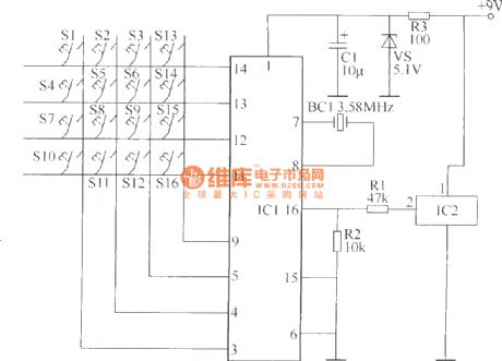
Wireless remote control transmitter circuit is composed of control buttons S1 ~ S16, resistors R1 ~ R3, capacitor C1 regulator diode VS, crystal oscillator BC1, DTMF encoder IC IC1 and IC2 wireless remote control transmitter integrated circuit components. It is shown as above.
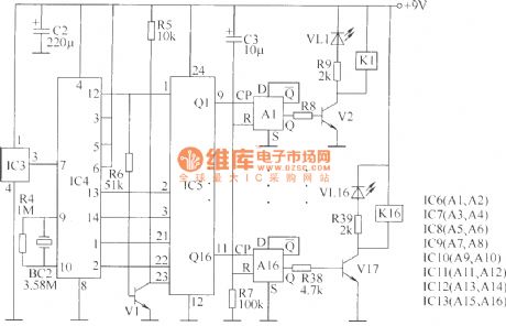
Components selectionR1, R2 and R4, R6 ~ R39 use 1/4W carbon film resistors or metal film resistors; R3 and R5 use 1/2W metal film resistors. C1 ~ C3 use 16V voltage aluminum electrolytic capacitors. VS uses 1/2W, 5.1V voltage regulator diode silicon. VL1 ~ VL16 use φ3mm common light-emitting diodes.V1 uses S9013 type silicon NPN transistor; V2 ~ V17 use C8050 or S8050, 3DG8050 silicon NPN transistor. IC1 uses UM95087 type phone with a selection of DTMF dialing code integrated circuits; IC2 uses HS101 type wireless remote control transmitter thick-film integrated circuits; IC3 uses HS201 type wireless remote control receiver thick film integrated circuit; IC4 uses MC145436 type telephone with DTMF decoder integrated circuits; IC5 uses CD4514 or MC14514 type 4-16 line decoder IC; IC6 ~ IC13 (D1 ~ D16) use CD4013 dual D flip-flop integrated circuits.
(View)
View full Circuit Diagram | Comments | Reading(3237)
Wireless remote control switch circuit 4
Published:2011/5/8 22:05:00 Author:Rebekka | Keyword: Wireless remote control switch
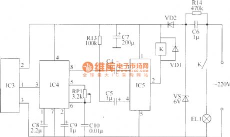
The wireless remote control switch circuit is composed of the wireless remote control transmitter circuitry and wireless remote control receiver control circuit. Wireless remote control transmitter circuit is composed of the controlled variable frequency oscillator and a wireless remote control transmitter circuit. It is shown as above.
Component selectionR1 ~ R14 use 1/4W carbon film resistors or metal film resistors. RP1 uses WSW type organic solid fine resistors. C1, C2 and C10 use monolithic capacitors; C3 ~ C5 and C8, C9 use aluminum electrolytic capacitor voltage 16V; C7 uses electrolytic capacitors voltage 25V; C6 uses 400V voltage polyester capacitor or CBB capacitors. VD1 and VD2 use 1N4007 type silicon rectifier diode.VS uses 1W, 6.2V silicon voltage regulator diodes. IC1 uses NE555 type base integrated circuit; IC2 uses TDC1808 type wireless remote control transmitter IC module; IC3 uses TDC1809 type wireless remote control receiver IC module; IC4 uses LM567 type audio PLL decoder IC; IC5 uses DM21 type dual steady-state driver IC module. K uses 6V DC relay. S1 ~ S10 use moving micro-Hop (open) button. (View)
View full Circuit Diagram | Comments | Reading(3195)
Digital code remote control switch circuit diagram
Published:2011/5/9 1:12:00 Author:Rebekka | Keyword: Digital code remote control switch
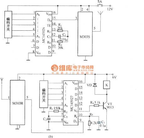
Digital code remote control switch circuit composed of digital codec MC145026/MC145027 andtiny radio transceivers M303S/M303R is shown as above.
Press the transmitter button SA, the circuit start to work. The serial encoded signal outputs from MC145026 to 15 feet, passes the transmitter module M303S and shoots out. The receiver module M303R of receiving circuit receives the encoded signals and sends to the decoder MC145027. When the address code of the encoder and decoder are exactly the same, the decoding of MC145027 effectively instructs a high-side output pulse signal. The transistor VT turns on, the drive relay pulls in. The switch control function will be completed.
(View)
View full Circuit Diagram | Comments | Reading(4467)
The car engine over-temperature alarm
Published:2011/7/22 21:12:00 Author:qqtang | Keyword: over-temperature alarm
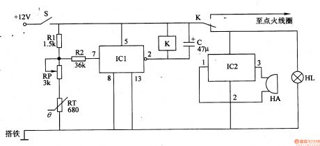
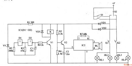
Here is to introduce the car engine over-temperature alarm which has the protection function, it can emitter alarm signal when the working temperature of the engine is too high and the temperature of the water tank is over 9O℃, at the same time, it will cut off the igniting power supply automatically to put out the engine.The working principle of the circuitThe car engine over-temperature alarm consists of the temperature detection control circuit and acousto-optic alarm circuit, see as figure 7-111.
(View)
View full Circuit Diagram | Comments | Reading(1647)
The car back-up alarm (2)
Published:2011/7/22 22:13:00 Author:qqtang | Keyword: back-up alarm
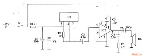
The working principle of the circuit The car back-up alarm consists of the sound alarm circuit and op-amp output circuit, see as figure 7-122.
The sound alarm circuit consists of the switch S, resistors of R1 and R2, capacitor C1, voltage stabilizing diode VS and 3-terminal sound alarm integrated circuit IC. The op-amp output circuit consists of the power amplifier integrated circuit IC2, capacitors C2-C5, resistor R3 and loudspeaker BL. (View)
View full Circuit Diagram | Comments | Reading(1233)
The car back-up alarm (3)
Published:2011/7/22 22:22:00 Author:qqtang | Keyword: back-up alarm
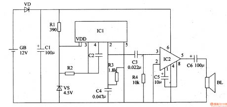
The car back-up alarm that will be introduced adopts the voice integrated circuit, which can make the alarm sound of ding-dong, back up to remind the pedestrian of safety.The working principle of the circuitThe car back-up alarm consists of the sound generator and the op-amp output circuit, see as figure 7-123.
The sound generator circuit consists of the resistors R1-R3, capacitors of C2 and C4, regulated diode VS and voice integrated circuit IC (View)
View full Circuit Diagram | Comments | Reading(1272)
The switch shut off time delay circuit diagram
Published:2011/5/8 7:10:00 Author:Rebekka | Keyword: The switch shut off time delay
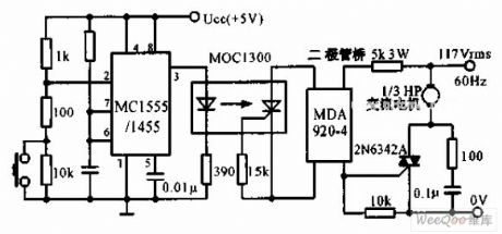
The switch shut off time delay circuit is shown as below. The switch shut off time delay circuit is composed of the timer, optocouplers, bridge SCR, SCR AC switch. When the control button is released, the keeping motor or other AC start power for 1 hour. Button closure. 2 pin voltage step-down Ucc / 3 below. The output pin 3 rises. LED lights. The bridge SCR AC switch TRIAC triggers the motor to run. The 7 feet of the capacitor began to charge at the same time. When the voltage rises to 2Ucc / 3 and the timer output decreases, the motor stops running. (View)
View full Circuit Diagram | Comments | Reading(4933)
Wireless remote control switch circuit diagram 1
Published:2011/5/8 21:37:00 Author:Rebekka | Keyword: Wireless remote control switch

This example describes a miniature wireless remote control transmitting and receiving wireless remote control switch device fabrication. It has a simple circuit, easy to build, debug and convenient. It can be used for short pulse trigger circuit or control the work of electrical equipment (such as electric curtains, Electric shutter doors, electric toys, etc.).
Select optional components R1 ~ R4 use 1/4W carbon film resistors or metal film resistors. RP uses solid variable resistors. C1 ~ C5 use monolithic capacitors. VD1 ~ VD3 use 1N4148 silicon switching diodes. V uses S8050 or C8050, 3DG8050 silicon NPN transistor.IC1 uses 630-type integrated wireless remote control transmitter T head; IC2 uses NE555 type base integrated circuit; IC3 uses IC1 supporting T631 type wireless remote control receiver; IC4 uses LM567 type based decoding IC. S uses moving together (normally open) type button. K uses 6V DC relay. The contact current capacity electrical power can be controlled.
(View)
View full Circuit Diagram | Comments | Reading(3762)
The automobile steering alarm (1)
Published:2011/7/22 21:18:00 Author:qqtang | Keyword: steering alarm

The working principle of the circuit The automobile steering alarm consists of the audio trigger circuit and audio amplifier output circuit, see as figure 7-124.
The audio trigger circuit consists of the resistors R1-R4, diodes of VD1 and VD2, capacitors of C1 and C2, regulated diodes of VS1-VS2 and audio integrated circuit IC1. The audio amplifier output circuit consists of the resistors C3-C6, resistor R5, audio power amplifier integrated circuit IC2 and loudspeaker BL. (View)
View full Circuit Diagram | Comments | Reading(516)
The automobile steering alarm (2)
Published:2011/7/22 21:25:00 Author:qqtang | Keyword: steering alarm
The working principle of the circuitThe automobile steering alarm consists of the square wave oscillator, flash control circuit and music generator circuit, see as figure 7-125.
The square wave oscillator consists of the NAND circuit IC1(D1 and D2), resistors R1-R3, regulated diode VS and capacitor C1.The flash control circuit consists of the resistor R4, transistor V1, diode VD3 and relay K.The music player consists of the transistor V2, resistors R5-R7, capacitor C2, music integrated circuit IC2 and loudspeaker BL.
(View)
View full Circuit Diagram | Comments | Reading(478)
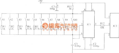
The 8-line inter-lock e-switch
Published:2011/7/22 9:13:00 Author:qqtang | Keyword: 8-line, inter-lock, e-switch
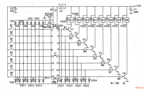
The working principle of the circuit This 8-line inter-lock e-switch circuit consists of the regulated filter circuit, input control circuit, lock storage circuit and the control executing circuit, see as figure 8-126.
The regulated filter circuit consists of the 3-terminal regulated integrated circuit IC1 and filter capacitors of C1 and C2。 The input control circuit consists control key Sl-S8 and diode VDl-VDl6. The lock storage circuit consists of 8 D trigger integrated circuits of IC2, reset key S9, resistors of R9 and R10, capacitor C3 and so on. (View)
View full Circuit Diagram | Comments | Reading(1391)
The temperature central controller
Published:2011/7/22 20:53:00 Author:qqtang | Keyword: central controller
In industrial manufacturing and scientific researches, an electric heating box is always coupled with a temperature controller, this often happens in the spots where there are many electric heating boxes. Here is to introduce the temperature central controller which can constantly control the temperature of many electric heating boxes(or electric oven and electric cooker).The working principle of the circuitThe temperature central controller consists of the power supply circuit and the constant temperature control circuit, see as figure 8-127.
(View)
View full Circuit Diagram | Comments | Reading(554)
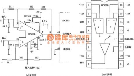
24dB two-way transmission isolation amplifier circuit composed of the OPA676
Published:2011/6/29 0:16:00 Author:Rebekka | Keyword: 24dB two-way transmission , isolation amplifier
The integrated chip's main parameters of the OPA676:
The figure shows the 24 dB two way transmission buffer amplifier circuit. It is widely used in many aspects. The OPA676 is a typical high-speed operation amplifier circuit, and its special use in the internal containing two ways. And each other is completely independent but its characteristics are completely symmetrical differential input level. The two input levels can be selected by TTL logic level. In other words, the OPA676 has two signal transmission channels, it is respectively marked as A and B channel. The OPA676 chip 12 pins are chosen ends of A, B channel.
(View)
View full Circuit Diagram | Comments | Reading(574)
The light control safety switch
Published:2011/7/22 7:11:00 Author:qqtang | Keyword: light control, safety switch
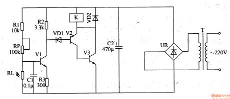
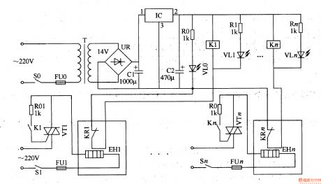
The working principle of the circuitThe light control safety switch circuit consists of the power supply circuit, light control circuit and control executing circuit(switch circuit), see as figure 8-128.
The power supply circuit consists of the power supply circuit T, rectifier bridge pile UR and filter capacitor C2.The light control circuit consists of the LDR RL, resistor Rl-R3, potentiometer RP, transistor V1 and capacitor C1.The control executing circuit consists of the diodes of VD1 and VD2, transistors V2 and V3, relay K and so on. (View)
View full Circuit Diagram | Comments | Reading(708)
Supply Camera Rail Car
Published:2011/7/19 6:50:00 Author:Sue | Keyword: Camera Rail Car, Imported, Photographic Rail Car


Features:
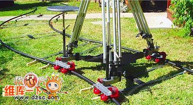
It can bear at most 200kg.
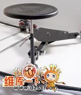
It can be equipped with any professional tripod, and can install a small camera arm.
It has a standard cameraman seat and a push bar which facilitates camera in seat and track sliding movement.
The track interface is seamlessly connected and is smooth and stable. The track width can be adjusted at random and is suitable fordifferent environments/filming sites.
The track uses aviation aluminum alloy which has 17 layers of surface coating and is not easy to wear out.
It doesn't need any installation tools and is portable and easy to use. It can solve the problems of low frequency which results from heavy stainless steel rail,overload and inconvenient transportation. (View)
View full Circuit Diagram | Comments | Reading(624)
| Pages:1453/2234 At 2014411442144314441445144614471448144914501451145214531454145514561457145814591460Under 20 |
Circuit Categories
power supply circuit
Amplifier Circuit
Basic Circuit
LED and Light Circuit
Sensor Circuit
Signal Processing
Electrical Equipment Circuit
Control Circuit
Remote Control Circuit
A/D-D/A Converter Circuit
Audio Circuit
Measuring and Test Circuit
Communication Circuit
Computer-Related Circuit
555 Circuit
Automotive Circuit
Repairing Circuit