
Circuit Diagram
Index 1443
TIME_DELAY_AUTO_KILL_SEITCH
Published:2009/6/16 2:29:00 Author:May
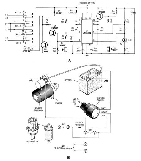
The automobile delayed kill switch is simple in concept. When you get out of your car, a secretly located pushbutton switch is pressed. Nothing apparently happens, but at the end of a predeter-mined time, a relay is pulled in and locked. When the relay is pulled in, contacts open, and the hot lead from the ignition to the coil and the hot wire from the key switch to the starter solenoid is opened or disconnected. If the engine is running, it stops immediately and the starter will not operate. When you get into the car, another pushbutton switch is pressed and the relay drops out and everything goes back to normal. (View)
View full Circuit Diagram | Comments | Reading(1343)
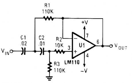
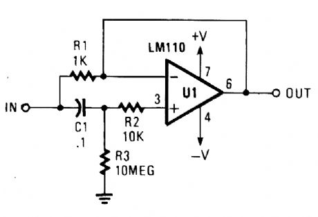
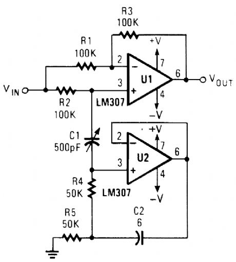
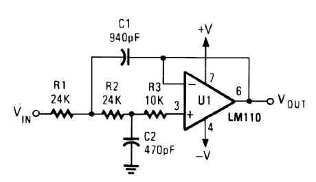
ACTIVE_HIGH_PASS_FILTER
Published:2009/6/16 2:27:00 Author:May
View full Circuit Diagram | Comments | Reading(957)
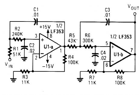
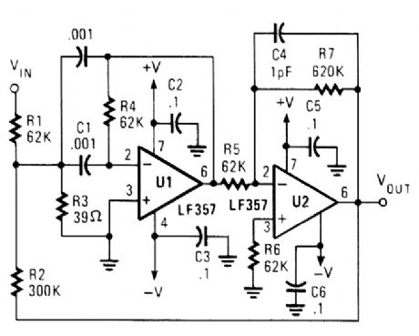
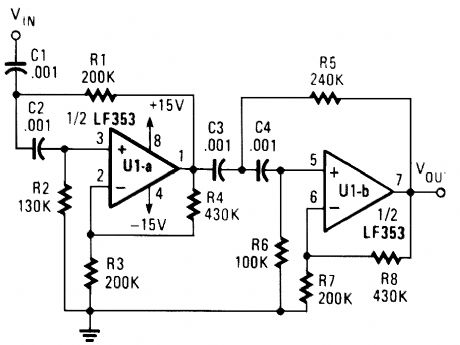
FOURTH_ORDER_LOW_PASS_BUTTERWORTH_FILTER
Published:2009/6/16 2:27:00 Author:May
View full Circuit Diagram | Comments | Reading(916)
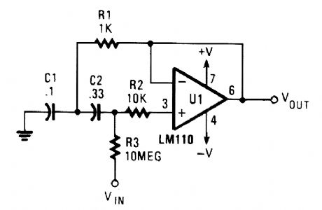
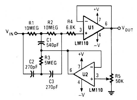
BANDPASS_FILTER
Published:2009/6/16 2:26:00 Author:May
View full Circuit Diagram | Comments | Reading(111)
AUTOMOTIVE_POWER_ADAPTER_FOR_dc_OPERATED_DEVICES
Published:2009/6/16 2:25:00 Author:May
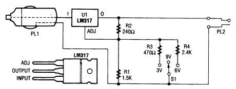
In the schematic diagram for the car-power adapter, note how the value of RB (which is R1 and S1 in the center position) is changed by putting R3 or R4 in parallel with R1. (View)
View full Circuit Diagram | Comments | Reading(561)
SIMULATED_INDUCTOR
Published:2009/6/16 2:25:00 Author:May
View full Circuit Diagram | Comments | Reading(1)
HIGH_Q_BANDPASS_FILTER
Published:2009/6/16 2:24:00 Author:May
View full Circuit Diagram | Comments | Reading(1929)
POWER_CONTROLLER_FOR_AUTOMOTIVE_ACCESSORIES
Published:2009/6/16 2:23:00 Author:May
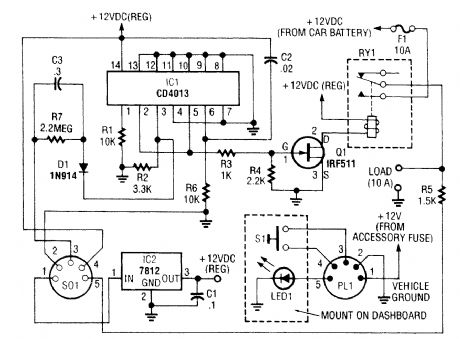
Because the power controller is powered from the vehicle's accessory switch, the load can receive power only when the ignition key is on. Using half of a dual flip-flop (CD4013), a load of up to 10 A is controlled by a momentary pushbutton. This circuit was originally intended for automotive power control, but could have other applications as well. (View)
View full Circuit Diagram | Comments | Reading(1339)
TUNABLE_NOTCH_FILTER
Published:2009/6/16 2:23:00 Author:May
View full Circuit Diagram | Comments | Reading(1209)
FOURTH_ORDER_HIGH_PASS_BUTTERWORTH_FILTER
Published:2009/6/16 2:22:00 Author:May
View full Circuit Diagram | Comments | Reading(977)
ADJUSTABLE_Q_NOTCH_FILTER
Published:2009/6/16 2:21:00 Author:May
View full Circuit Diagram | Comments | Reading(2)
FLASHING_BRAKE_LIGHT
Published:2009/6/16 2:19:00 Author:May
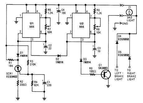
When power is first applied, three things happen: the light-driving transistor (Q1) is switched on because of a low output from U2, pin 3; timer U1 begins its timing cycle, with the output (pin 3) going high, inhibiting U2's trigger (pin 2) via D2; and charge current begins to move through R3 and R4 to C1.When U1's output goes low, the inhibiting bias on U2 pin 2 is removed, so U2 begins to oscillate, flashing the third light via Q1, at a rate determined by R8, R6, and C3. Oscillation continues until the gate-threshold voltage of SCR1 is reached, causing it to fire and pull U1's trigger (pin 2) low. With its trigger low, U1's output is forced high, disabling U2's triggering. With triggering inhibited, U2's out-put switches to a low state, which makes Q1 conduct, turning on I1 until the brakes are released. Removing power from the circuits resets SCR1, but the RC network consisting of R4 and C1 will not discharge immediately and will trigger SCR1 earlier. So, frequent brake use means fewer flashes.Bear in mind that the collector/emitter voltage drop across Q1, along with the loss across the series-fed diodes, reduces the maximum available light output. If the electrical system is functioning properly (at 13 to 14 V for most vehicles), those losses will be negligible. (View)
View full Circuit Diagram | Comments | Reading(753)
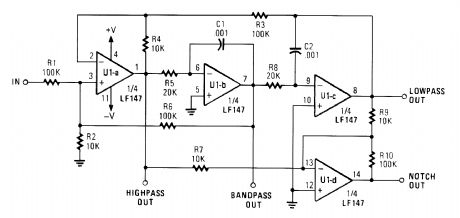
UNIVERSAL_STALE_VARIABLE_FILTER
Published:2009/6/16 2:19:00 Author:May
View full Circuit Diagram | Comments | Reading(667)
HIGH_Q_NOTCH_FILTER
Published:2009/6/16 2:18:00 Author:May
View full Circuit Diagram | Comments | Reading(1)
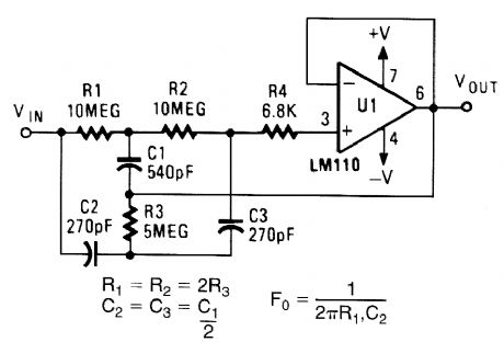
ACTIVE_LOW_PASS_FILTER
Published:2009/6/16 2:18:00 Author:May
View full Circuit Diagram | Comments | Reading(818)
SIMPLE_FIELD_STRENGTH_METER_Ⅱ
Published:2009/6/16 2:16:00 Author:May
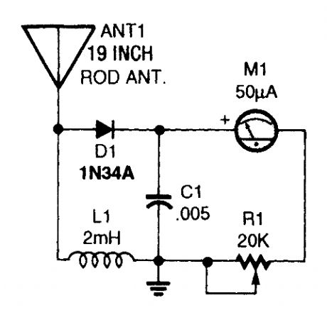
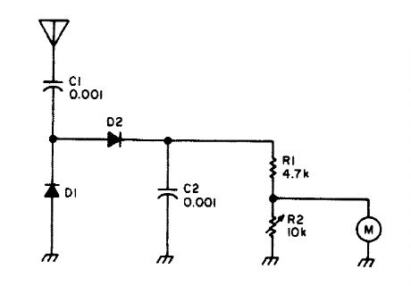
This simple field-strength meter provides a cheap way to monitor an amateur radio or CB transmitter (or even an antenna system) for maximum output. (View)
View full Circuit Diagram | Comments | Reading(1388)
SIMPLE_FIELD_STRENGTH_METER_I
Published:2009/6/16 2:15:00 Author:May
Useful for checking transmitters and anten-nas, this circuit uses a voltage-doubling detector D1 and D2 (HP 5082-2800 hot carrier types). D1 and D2 can also be type IN34 or IN82. M is a 100-mA meter movement. (View)
View full Circuit Diagram | Comments | Reading(677)
SIMPLE_AMPLIFIED_FIELD_STRENGTH_METER
Published:2009/6/16 2:14:00 Author:May


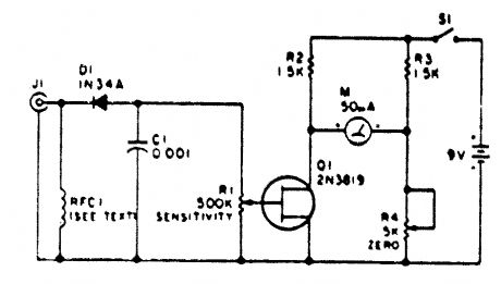
This circuit uses a FET as a dc amplifier in a bridge circuit. R4 is set for meter null with J1 short circuited. Any surplus 50-mA meter can serve in this circuit. RFC1 is any suitable RE choke for the band in use. A 2.5-mH RE choke will do for broadband operation. R1 is a sensitivIty control. The antenna can be any small whip antenna (2 ft or less). (View)
View full Circuit Diagram | Comments | Reading(1087)
THERMOSTAT_SEITCH_FOR_AUTOMOTIVE_ELECTRIC_FANS
Published:2009/6/16 2:13:00 Author:May
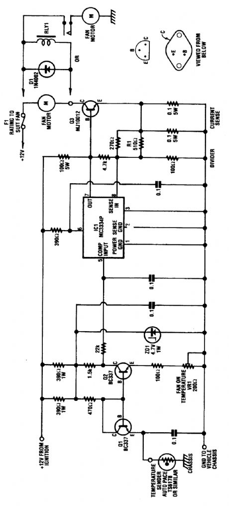
The circuit is based on a commercial temperature sensor(TS6178) and an MC3334P ignition chip. When the radiator temperature increases, the sensor pulls the base of Q2 low via Q1, which is wired as a diode. Q2's collector thus goes high and triggers IC1, which seitches its pin 7 output high and turns on the fan motor via Q3. (View)
View full Circuit Diagram | Comments | Reading(688)
AMPLIFIED_FIELD_STRENGTH_METER
Published:2009/6/16 2:11:00 Author:May
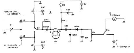
FET Q1 acts as an RF amplifier to boost sensitivity of the usual diode detector field strength meter. (View)
View full Circuit Diagram | Comments | Reading(2427)
| Pages:1443/2234 At 2014411442144314441445144614471448144914501451145214531454145514561457145814591460Under 20 |
Circuit Categories
power supply circuit
Amplifier Circuit
Basic Circuit
LED and Light Circuit
Sensor Circuit
Signal Processing
Electrical Equipment Circuit
Control Circuit
Remote Control Circuit
A/D-D/A Converter Circuit
Audio Circuit
Measuring and Test Circuit
Communication Circuit
Computer-Related Circuit
555 Circuit
Automotive Circuit
Repairing Circuit