
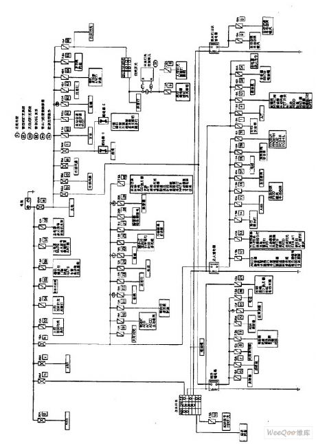
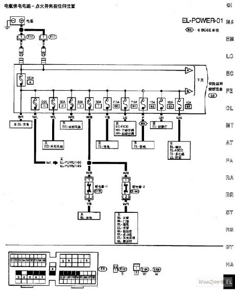
Circuit Diagram
Index 1454
Nissan A32-EL Power Supply Circuit (7)
Published:2011/7/15 5:22:00 Author:Sue | Keyword: Nissan, Power Supply
View full Circuit Diagram | Comments | Reading(914)
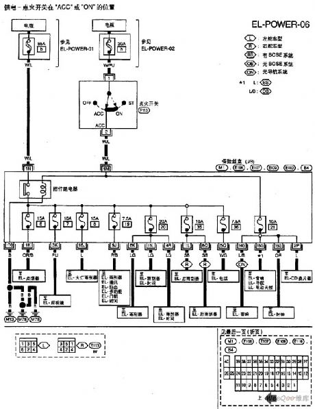
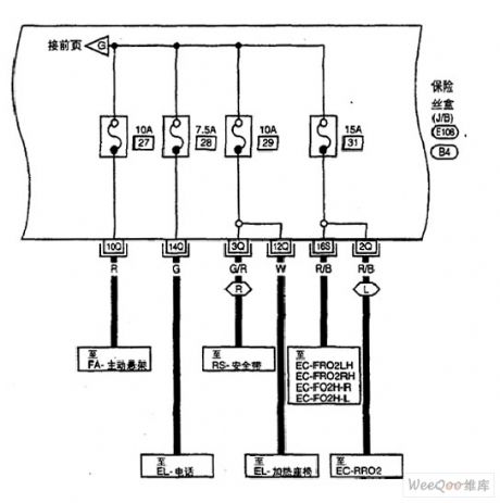
Nissan A32-EL Power Supply Circuit (8)
Published:2011/7/15 5:21:00 Author:Sue | Keyword: Nissan, Power Supply
View full Circuit Diagram | Comments | Reading(835)
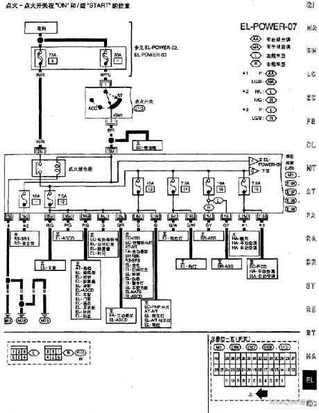
Nissan A32-EL Power Supply Circuit (11)
Published:2011/7/15 5:20:00 Author:Sue | Keyword: Nissan, Power Supply
View full Circuit Diagram | Comments | Reading(887)
Nissan A32-EL Rear Foglamp Circuit
Published:2011/7/15 5:25:00 Author:Sue | Keyword: Nissan, Rear Foglamp
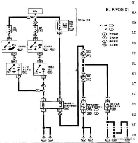
View full Circuit Diagram | Comments | Reading(741)
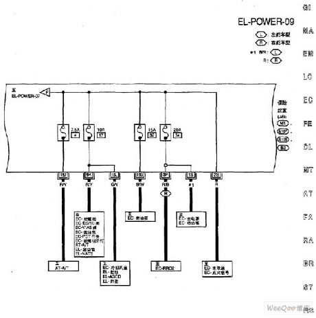
Nissan A32-EL Power Supply Circuit (9)
Published:2011/7/15 5:19:00 Author:Sue | Keyword: Nissan, Power Supply
View full Circuit Diagram | Comments | Reading(852)
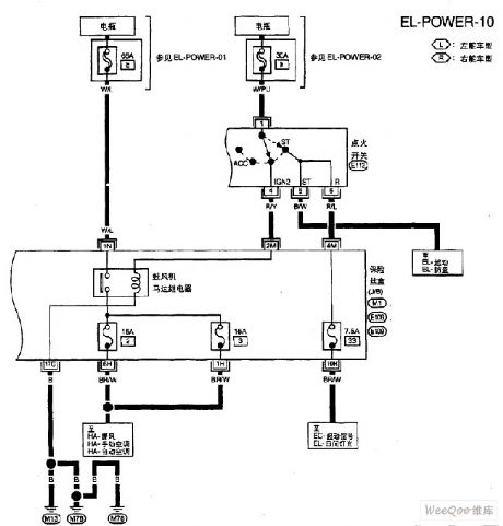
Nissan A32-EL Power Supply Circuit (10)
Published:2011/7/15 5:18:00 Author:Sue | Keyword: Nissan, Power Supply
View full Circuit Diagram | Comments | Reading(772)
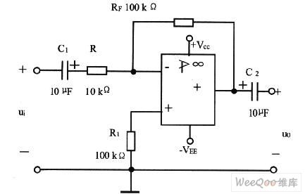
Differential Feeder Line Driver Circuit
Published:2011/7/18 2:57:00 Author:Sue | Keyword: Differential, Feeder Line, Driver
The picture shows the differential feeder line driver circuit. (View)
View full Circuit Diagram | Comments | Reading(604)
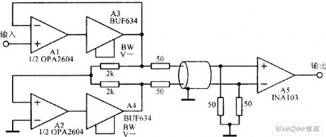
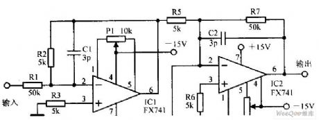
Balanced Output Circuit Composed of Double Operational Amplifier
Published:2011/7/18 2:55:00 Author:Sue | Keyword: Balanced, Output, Double, Operational Amplifier
The picture shows the balanced output circuit composed of double operational amplifier. (View)
View full Circuit Diagram | Comments | Reading(2964)
Precise Bridge Sensor Amplifier Circuit
Published:2011/7/18 2:51:00 Author:Sue | Keyword: Precise, Bridge, Sensor Amplifier
The picture shows the precise bridge sensor amplifier circuit. (View)
View full Circuit Diagram | Comments | Reading(653)
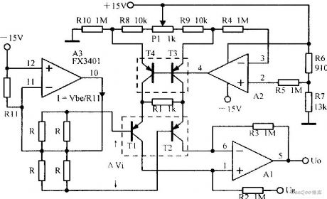
Instrumentation Amplifier Circuit with High Common-mode Range
Published:2011/7/18 2:49:00 Author:Sue | Keyword: Instrumentation Amplifier, High Common-mode
The picture shows the instrumentation amplifier circuit with high common-mode range. (View)
View full Circuit Diagram | Comments | Reading(483)
The light control approaching switch circuit
Published:2011/7/22 9:33:00 Author:qqtang | Keyword: light control, approaching switch

The working principle of the circuitThe light control approaching switch circuit consists of the LDR RG, pressure sensitive resistor RV, transistors of V1 and V2, resistor Rl-R5, capacitors of C1 and C2, regulated diode VS, thyristor VT and diodes VDl-VD5, etc, see as figure 8-130.
Usually, RG is in a low LEV due to the light, V1 and V2 are both conducting, VT is blocked, the middle relay KA is in the releasing state, its normally closed contactor is conducting, the load is getting power and working. (View)
View full Circuit Diagram | Comments | Reading(634)
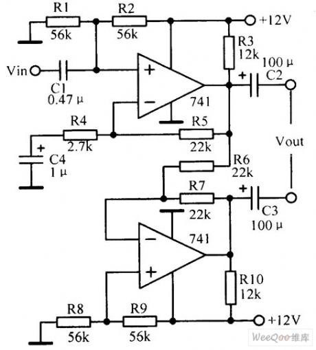
Duplicate Power Supply Reversed-Phase Input Alternating Current Amplifier Circuit
Published:2011/7/18 7:59:00 Author:Sue | Keyword: Duplicate Power Supply, Reversed-Phase, Input, Alternating Current, Amplifier
View full Circuit Diagram | Comments | Reading(570)
Numbers Padlock Integrated Circuit
Published:2011/7/14 7:06:00 Author:Sue | Keyword: Numbers, Padlock, Integrated
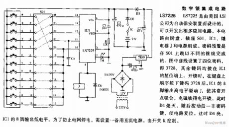
LS7225 is designed by American LSI company for automatic protective device, which can develop many application circuit. The circuit consists of keyboard, socket S01,IC1, relay J and power supply. The code preset is finished by connecting different wirings to S01. As seen in the figure, a four figures code is set, that is 3728, while other key codes are all on IC1's reset terminal. When to open the padlock, after pushing the key codes 3728 inproper order on the keyboard, IC1's pin 8 will output high level which will drive J to work which will make its normally open point connected. The electromagnet will get power to open the padlock, and D4 will go out. Then if any non-code key is pushed, the circuit will be reset and D4 is illuminated. IC1's pin 8 will output low level. In order to prevent the electrified wire netting from losing electricity, a spare current power is needed which is controlled by switch K. (View)
View full Circuit Diagram | Comments | Reading(917)
SBT-420AT Lightening Protection Socket
Published:2011/7/19 7:33:00 Author:Sue | Keyword: Lightening Protection, Socket
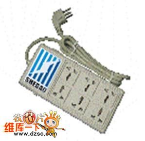
Functions and features:
SBT-420AT lightening protection socket has features of large current capacity, low residual voltage, over current insurance, high-frequency filtering. It uses advanced production technology. The lightening protection components all use brand-name products: the outer covering uses high-quality flame-retardant material;the socket components use high-quality phosphor bronze. (View)
View full Circuit Diagram | Comments | Reading(596)
Toyota Land Cruiser 70 light off-road vehicle differential lockand door lock principle circuit diagram
Published:2011/5/8 12:41:00 Author:Rebekka | Keyword: Toyota Land Cruiser 70, light off-road vehicle, differential lockand door lock
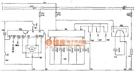
Toyota Land Cruiser 70 light off-road vehicle differential lockand door lock principle circuit diagram.
160 differential lock indicator light; 161 differential lock switch; 162 electronic differential lock control device; 163 differential lock motor; 164 door lock relay; 165 lock valve (pilot , the right crew, the crew left rear); 166 door lock switch (driver side); 167 door lock switch (no power windows and doors); 168 control switch (main switch electric windows and doors); 169 baggage door lock switch; 170 baggage door lock solenoid valve; 171 fuel heater; 69 combination instruments 7D terminal(four-wheel drive indicator light); 92 speed sensor.
(View)
View full Circuit Diagram | Comments | Reading(1775)
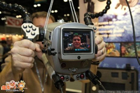
Supply Camera Car Sucker
Published:2011/7/19 7:16:00 Author:Sue | Keyword: Camera Car Sucker, Camera Sucker Eauipment, Supporting Bar, Vehicle Photography

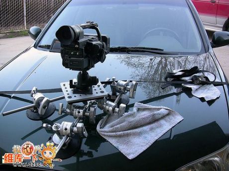
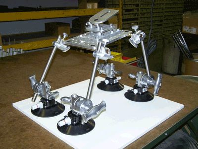
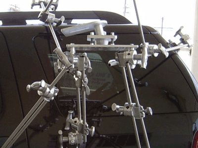
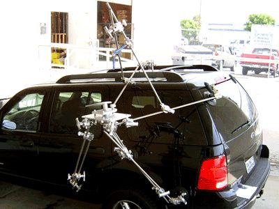
Camera Car Sucker.
Camera car suckers can be divided into three suckers, four suckers and multi-suckers. Any combination can be made according to cameras of different sizes.
It is suitable for automobile photography, moving photography, advertising photography, special effect photography. It is widely used in film and television play.
Four Suckers Equipment.
Multi-sucker Equipment.
Camera car sucker equipment includes:
Sucker, camera installation platform, universal joint, standing bar, rod, strap and carrying case.
(View)
View full Circuit Diagram | Comments | Reading(712)
Professional Secret Investigation Equipment
Published:2011/7/19 6:26:00 Author:Sue | Keyword: Secret Investigation, Candid


Features and Functions:
The microwave transmitter unit uses standard definition colorful SONY CCD digital camera and high sensitivity microphone. It has functions as simultaneous recording, transmission of audio and video signals.
It has internal 500mW transmitter and can use hard disk recording equipment. The micro-element code control circuit developed by our company and Japanese SONY, French DVR will realise remote control of the records.
The package transmitter uses DC10.8V, 1.5AH lithium battery as power supply and has a power supply time not shorter than 3 hours.
It uses imported components and modules which is of high quality with high cost performance. (View)
View full Circuit Diagram | Comments | Reading(548)
Supply Camera Cofferdam
Published:2011/7/19 5:58:00 Author:Sue | Keyword: Camera Cofferdam, Diving Equipment, Underwater Photographic Equipment


Product Features:
The top viewfinder provides a clear picture of the camera monitor.
It has internal voltage regulator system which is designed for the buoyancy of water.
When the macro lens are touched, the microbe can be amplified doubly.
If there is no light, it will be an effective solution to touch the color correction filter. When the external operating arm is touched, the color correction filter will be indented.
The precise light combined with IR control makes it possible to control the lighting system at your fingertips.
It has waterproof alarm bell with visual and hearing functions.
Option: Suitcase, lighting. (View)
View full Circuit Diagram | Comments | Reading(569)
Nissan A32-EL Power Supply Circuit (1)
Published:2011/7/14 7:24:00 Author:Sue | Keyword: Nissan, Power Supply
View full Circuit Diagram | Comments | Reading(821)
Nissan A32-EL Power Supply Circuit (2)
Published:2011/7/14 7:26:00 Author:Sue | Keyword: Nissan, Power Supply
View full Circuit Diagram | Comments | Reading(797)
| Pages:1454/2234 At 2014411442144314441445144614471448144914501451145214531454145514561457145814591460Under 20 |
Circuit Categories
power supply circuit
Amplifier Circuit
Basic Circuit
LED and Light Circuit
Sensor Circuit
Signal Processing
Electrical Equipment Circuit
Control Circuit
Remote Control Circuit
A/D-D/A Converter Circuit
Audio Circuit
Measuring and Test Circuit
Communication Circuit
Computer-Related Circuit
555 Circuit
Automotive Circuit
Repairing Circuit