
Circuit Diagram
Index 1461
The car brake lamp fault monitor (1)
Published:2011/7/23 20:59:00 Author:qqtang | Keyword: brake lamp, fault monitor
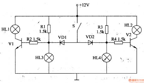
Whether the brake lamp is good directly affects the safety of the following car. Here is to introduce the car brake lamp fault monitor, which can find the broken lamp, reduce the traffic accidents and make sure the car is safe.The working principle of the circuit The car brake lamp fault monitor consists of the resistors V1 and V2, diodes VD1 and VD2, resistors R1-R4 and indicators HL1 and HL2, see as figure 7-53.
(View)
View full Circuit Diagram | Comments | Reading(600)
Differential Integrator Circuit
Published:2011/7/21 1:05:00 Author:Sue | Keyword: Differential, Integrator
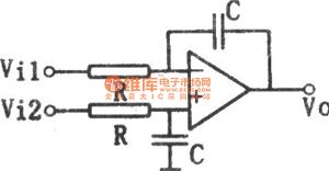
The picture shows the differential integrator circuit. Put R,C on the same phase side of the basic integrator according to the balanced symmetrical structure, then we will get such differential integrator circuit.
Figure1 Differential Integrator Circuit (View)
View full Circuit Diagram | Comments | Reading(2890)
Low Drift Differentiator Circuit
Published:2011/7/22 7:29:00 Author:Sue | Keyword: Low Drift, Differentiator
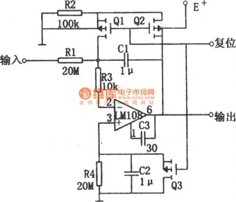
The differentiator shown in the circuit has small drift which will not exceed 500μV/s within the temperature rangefrom -55C to +125C. In the picture, the basic differentiator consists of operational amplifier, resistor R1 and capacitor C1. In order to improve the stability of the differentiator, the circuit adds resistor R4 and capacitor C2(R4=R1,C2=C1) to the operational amplifier's non inverting input terminal which will differentiate the input bias current. When the circuit is reset, field effec tube Q1 and Q2 will make the capacitor C1 short, which will prevent the input bias current from causing offset voltage. When Q1 and Q2are disconnected, the circuit begins to integrate. Then the bias current which flows through R1 will generate offset voltage. (View)
View full Circuit Diagram | Comments | Reading(686)
The car brake lamp fault monitor (2)
Published:2011/7/23 21:07:00 Author:qqtang | Keyword: brake lamp, fault monitor
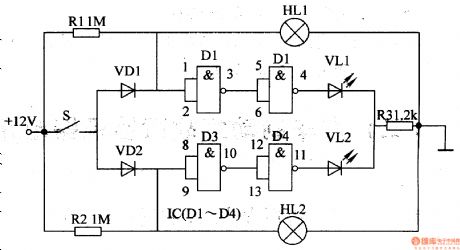
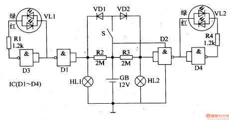
The working principle of the circuit (2)The car brake lamp fault monitor consists of resistors R1-R3, diodes VD1 and VD2, NOR gate integrated circuit IC(Dl-D4), LED VL1 and VL2, see as figure 7-54.
S is the car brake lamp switch, HL1 and HL2 are both the car brake lamps.Before the pedal is stepped down, S is in the breakdown state, both VD1 and VD2 are blocked, Nor gates D1 and D3 are both outputting high LEV, both D2 and D4 are outputting low LEV, neither of VL1 and VL2 is glowing. (View)
View full Circuit Diagram | Comments | Reading(1132)
The car brake lamp fault monitor (3)
Published:2011/7/23 21:12:00 Author:qqtang | Keyword: brake lamp, fault monitor
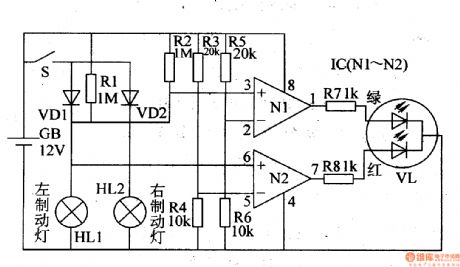
The working principle of the circuitThe car brake lamp fault monitor consists of the dimming LED VL, op-amp integrated circuit IC(N1 and N2) and relevant external elements, see as figure 7-55.
In the circuit, GB is the car storage battery, S is the brake switch, HL1 and HL2 are the left brake lamp and right brake lamp, respectively.
(View)
View full Circuit Diagram | Comments | Reading(581)
The car brake lamp fault monitor (4)
Published:2011/7/23 21:18:00 Author:qqtang | Keyword: brake lamp, fault monitor
Here is to introduce a car brake lamp fault monitor circuit which is made of the CD4011 digital integrated circuit(4 NAND). The working principle of the circuitFigure 7-56 is the The car brake lamp fault monitor circuit
In the circuit, HL1 is the left brake lamp, HL2 is the right brake lamp, resistors R2 and R3 form 2 circuits with brake lamps HL1 and HL2. S is the brake switch, GB is the car battery. (View)
View full Circuit Diagram | Comments | Reading(573)
The car brake lamp fault monitor (5)
Published:2011/7/23 21:22:00 Author:qqtang | Keyword: brake lamp, fault monitor
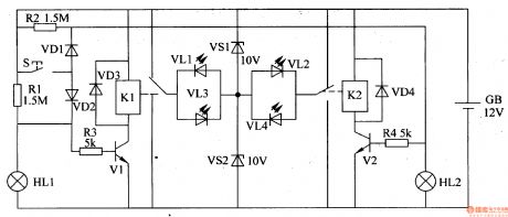
Here is to introduce a car brake lamp fault monitor circuit which is made of the separated element, it can detect the working state of the brake lamp and indicate the state with LED.The working principle of the circuitThe car brake lamp fault monitor circuits consists of the transistors V1 and V2, relays K1 and K2, diodes VD1-VD4, regulated diodes VS1 and VS2, LED VLl-VU and resistors R1-R4, see as figure 7-57.
(View)
View full Circuit Diagram | Comments | Reading(492)
The engine oil volume detector
Published:2011/7/23 8:46:00 Author:qqtang | Keyword: oil volume detector
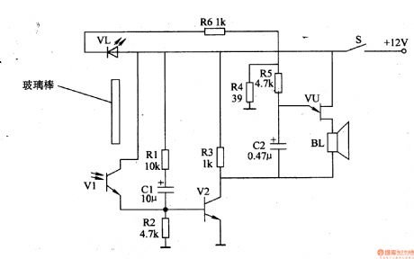
The working principle of the circuitThe engine oil volume detector consists of the photoelectric control circuit and sound alarm circuit, see as figure 7-63.
The photoelectric control circuit consists of the LED VL, light sensitive transistor V1, resistors of R1-R3 and R6, capacitor C1 and transistor V2.The sound alarm circuit consists of the resistor(R4, R5), capacitor C2, single knot transistor VU and loudspeaker BL. (View)
View full Circuit Diagram | Comments | Reading(749)
The vehicle headlight monitor
Published:2011/7/23 4:08:00 Author:qqtang | Keyword: headlight monitor

The working principle of the circuit The vehicle headlight monitor circuit consists of the light sensitive transistor V1, transistors of V2 and V3, buzzer HA, LED VL and so on, see as figure 7-64.
At daytime, the phototransistor V1 is in a low LEV due to the light, so V2 is blocked due to the low LEV of its basic pole. If the driver forgets to shut off the headlight or mistakenly turn on the headlight, the basic pole of V3 will be in a low LEV, which makes V2 conducting, the buzzer HA is emitting the alarm sound, meanwhile, the LED VL is glowing. (View)
View full Circuit Diagram | Comments | Reading(747)
The automobile brake fluid monitor
Published:2011/7/23 4:00:00 Author:qqtang | Keyword: brake fluid monitor
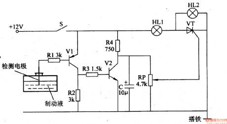
The working principle of the circuit The automobile brake fluid monitor circuit consists of the liquid level detection circuit and storage liquid state indicating circuit, see as figure 7-65.
The liquid level detection circuit consists of the detection polarity, capacitor C, resistors R1-R4, transistors of V1 and V2. The storage fluid state indicating circuit consists of the indicators of HL1 and HL2, potentiometer RP and thyristor VT. When the key S is pressed, the whole machine is getting power and working. (View)
View full Circuit Diagram | Comments | Reading(2075)
The car signal lamp monitor
Published:2011/7/23 3:54:00 Author:qqtang | Keyword: signal lamp, monitor
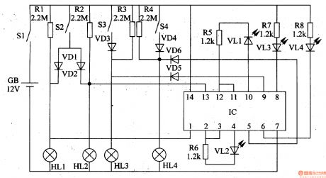
After the signal lamp is broken, if it is not replaced in time, the car is easy to cause accidents. Here is to introduce a car signal lamp monitor, which can emit red light alarm to remind the driver when the brake lamp or the turn lamp is malfunctioning.The working principle of the circuitThe car signal lamp monitor circuit consists of the diodes VD1-VD6, LED VL1-VL4, 6 NOR gate circuit IC and the external elements, see as figure 7-66.
(View)
View full Circuit Diagram | Comments | Reading(635)
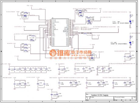
The computer mainboard circuit 830_42
Published:2011/7/20 8:11:00 Author:qqtang | Keyword: computer mainboard
View full Circuit Diagram | Comments | Reading(492)
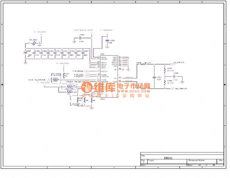
The computer mainboard circuit 830_43
Published:2011/7/20 8:10:00 Author:qqtang | Keyword: computer mainboard
View full Circuit Diagram | Comments | Reading(519)
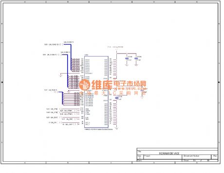
The computer mainboard circuit 830_44
Published:2011/7/20 8:09:00 Author:qqtang | Keyword: computer mainboard
View full Circuit Diagram | Comments | Reading(548)
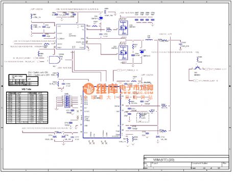
The computer mainboard circuit 830_45
Published:2011/7/20 8:08:00 Author:qqtang | Keyword: computer mainboard
View full Circuit Diagram | Comments | Reading(526)
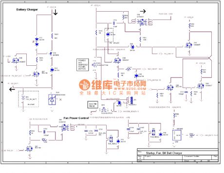
The computer mainboard circuit 830_46
Published:2011/7/20 8:07:00 Author:qqtang | Keyword: computer mainboard
View full Circuit Diagram | Comments | Reading(517)
The fuse box indicator (2)
Published:2011/7/23 21:50:00 Author:qqtang | Keyword: fuse box, indicator
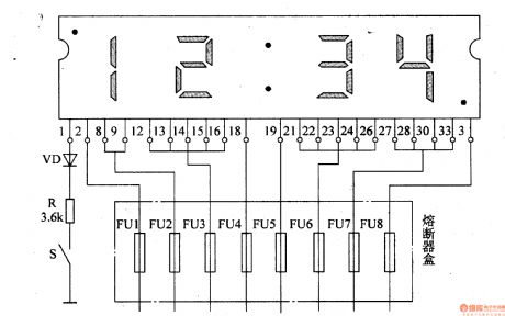
Here is to introduce a fuse box which utilizes the digital display to monitor and indicate the working state of the car fuse box, it characterizes direct display and convenient search.The working principle of the circuitThe fuse box indicator circuit consists of the digital display of integrated circuit type, diode VD, resistor R and power supply switch S, see as figure 7-45.
(View)
View full Circuit Diagram | Comments | Reading(599)
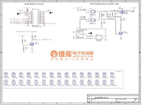
The computer mainboard circuit 830_47
Published:2011/7/20 8:06:00 Author:qqtang | Keyword: computer mainboard
View full Circuit Diagram | Comments | Reading(521)
The computer mainboard circuit 830-48
Published:2011/7/20 8:05:00 Author:qqtang | Keyword: computer mainboard
View full Circuit Diagram | Comments | Reading(560)
The computer mainboard circuit 830-49
Published:2011/7/20 8:04:00 Author:qqtang | Keyword: computer mainboard
View full Circuit Diagram | Comments | Reading(534)
| Pages:1461/2234 At 2014611462146314641465146614671468146914701471147214731474147514761477147814791480Under 20 |
Circuit Categories
power supply circuit
Amplifier Circuit
Basic Circuit
LED and Light Circuit
Sensor Circuit
Signal Processing
Electrical Equipment Circuit
Control Circuit
Remote Control Circuit
A/D-D/A Converter Circuit
Audio Circuit
Measuring and Test Circuit
Communication Circuit
Computer-Related Circuit
555 Circuit
Automotive Circuit
Repairing Circuit