
Circuit Diagram
Index 1480
HM9900 touching delay light circuit
Published:2011/7/20 19:03:00 Author:Lucas | Keyword: touching delay light
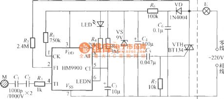
The circuit shown in the chart is the touching light delay circuit which is composed of the HM9900 specific integrated circuit, which has LED driver output usually to drive light emitting diode LED glow to look for the switch position at night.
(View)
View full Circuit Diagram | Comments | Reading(704)
The gas limiting alarm mining lamp circuit diagram 3
Published:2011/7/14 20:40:00 Author:Lucas | Keyword: Gas limiting, alarm , miners lamp
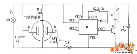
The gas limiting alarm miner's lamp circuit is composed of the gas detection circuit, electronic switch circuit and audio alarm circuit, and the circuit is shown as the chart. The gas detection circuit is composed of the resistor R1, potentiometer RP and gas sensor. Electronic switch circuit is composed of the thyristor VT and RP. Audio alarm sound is composed of the integrated circuit IC, resistor R2, transistor Ⅴ and speaker BL. R1 and R2 use 1/4W carbon film resistors or metal film resistors. C selects select aluminium electrolytic capacitors with the voltage in 6.3V. V uses 59013 or 3DG12 NPN silicon transistor. VT uses MCR100-6 or BTl69 thyristor.
(View)
View full Circuit Diagram | Comments | Reading(769)
The gas limiting alarm mining lamp circuit diagram 2
Published:2011/7/14 20:40:00 Author:Lucas | Keyword: Gas limiting , alarm , miners lamp
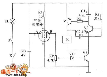
The gas limiting alarm miner's lamp circuit is composed of the gas detection circuit, controlled oscillator circuit and lighting circuit, and the circuit is shown as the chart. Gas detection circuit is composed of the gas sensor, resistor R1 and potentiometer RP. Controlled oscillator circuit is composed of the potentiometer RP, diode VD, transistors V1 ~ V3, resistors R2 and R3, capacitors C1 and C2 and the relay K. Lighting circuit is composed of the battery GB, light EL, light switch S and the normally closed contact of K. The miner's lamp EL is lit by turning on the light switch S, . R1 ~ R3 select 1/4W metal film resistors. RP uses small synthetic carbon potentiometer or variable resistor. C1 and C2 select aluminium electrolytic capacitors with the voltage in 6.3V.
(View)
View full Circuit Diagram | Comments | Reading(1141)
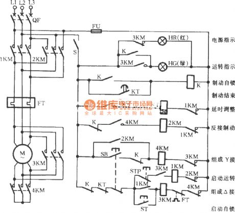
Y-shaped three-phase motor reverse brake circuit
Published:2011/7/14 20:30:00 Author:Lucas | Keyword: three-phase motor, 3KM
View full Circuit Diagram | Comments | Reading(1100)
Three-phase motor for jog brake circuit(a)
Published:2011/7/14 20:31:00 Author:Lucas | Keyword: KT2, Three-phase motor, jog brake
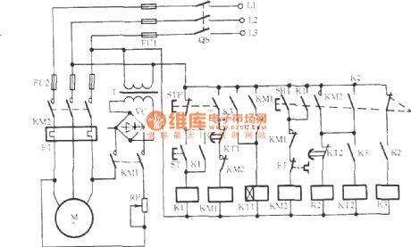
Many mechanisms not only require fast and correct parking, but also require jog brake. In order to improve the efficiency and positioning accuracy, the three-phase motor for jog brake circuit is used.
(View)
View full Circuit Diagram | Comments | Reading(1278)
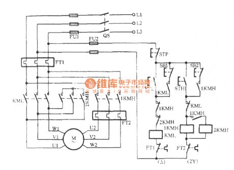
Three-phase motor dual-speed 2Y / △ connection speed control circuit (c)
Published:2011/7/14 20:33:00 Author:Lucas | Keyword: Three-phase motor, 2Y / △ connection
View full Circuit Diagram | Comments | Reading(4028)
Three-phase electric dual-speed 2Y / △ connection speed control circuit(b)
Published:2011/7/14 20:32:00 Author:Lucas | Keyword: dual-speed 2Y / △ connection

View full Circuit Diagram | Comments | Reading(1120)
Mine locomotive remote controller
Published:2011/7/20 19:30:00 Author:Lucas | Keyword: Mine locomotive , remote controller
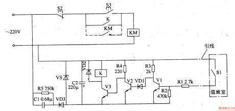
The mine locomotive remote controller circuit consists of transistors Vl-V3, capacitors Cl and C2, resistors Rl-R5, diodes VDl and VD2, control switch Sl and Zener diode VS, and the circuit is shown in Figure 8-35. Stop button S2, start button S3, AC contactor KM and normally open contact K form the main control circuit of the stepless rope motor M (it is not shown in the chart). VS, Cl, C2, R5 and VD3 form the integral power supply circuit, and the control switch S1 is installed in the duty room, and one end is grounded, the other end is connected to R1 by the leading wire.
(View)
View full Circuit Diagram | Comments | Reading(610)
555 positive voltage converting to 5v power supply circuit
Published:2011/7/24 4:06:00 Author:Lucas | Keyword: 555 positive voltage , 5v power supply
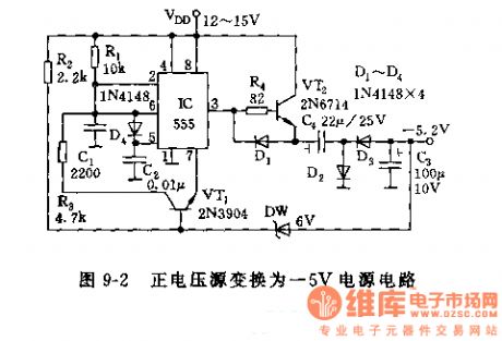
The 555 and R1, C1, VT1 and other components in Figure 9-2 form a multivibrator with the oscillation frequency being determined by R1, C1, R3 . C1 charges through R1, when the the potential of pin 6 charges to above 2/3 VDD of the threshold level, the 555 resets, pin 3 is at low level. DW is a Zener diode, when the negative output voltage is prompted to turn on D5, VT1 remains cut-off state. When the load current makes C1 discharge to a certain extent, D5 is deadline, and VT1 is turned on, then C1 begins to charge. The oscillation frequency of 555 changes with a certain load. Power load adjusted rate is about 1.5%.
(View)
View full Circuit Diagram | Comments | Reading(878)
74 series of digital circuit, 74143,74144 4-bit counter / latch, seven-segment LED / lamp driver
Published:2011/7/24 4:32:00 Author:Lucas | Keyword: 74 series , digital circuit, 4-bit counter , 4-bit latch, seven-segment LED , lamp driver
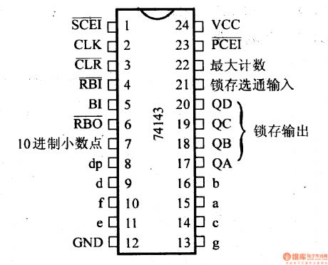
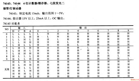
The constant current of 74143 is 15mA, and the output range is 1-5V; the indicating voltage of 74144 is above 15V, and current is more than 25mA with OC output. 74145 functional table
(View)
View full Circuit Diagram | Comments | Reading(2339)
74 series digital circuit of 74LS424 two-phase clock generator/driver
Published:2011/7/21 3:24:00 Author:Lucas | Keyword: 74 series , digital circuit , two-phase clock generator, two-phase clock driver
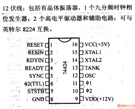
It is used to drive all 8080A microprocessors and 12V lines; it includes crystal oscillator, a nine-frequency clock phase generator, 2 high-level driver and auxiliary circuit; it can exchange with the Intel 8224.
(View)
View full Circuit Diagram | Comments | Reading(1124)
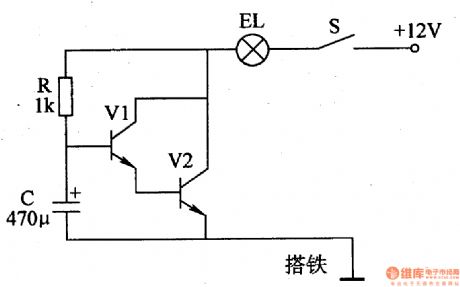
Mine spray dust removal controller
Published:2011/7/24 4:12:00 Author:Lucas | Keyword: Mine spray dust , removal controller
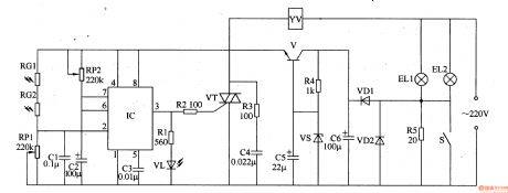
The mine spray dust removal controller circuit consists of +6 V power supply circuit, light control circuit, LED indication circuit and solenoid valve control circuit, and it is shown in Figure 8-34. +6 V power supply circuit is composed of the lights ELl, EL2, resistor R4, R5, switch S, the diode VDl, VD2, filter capacitors C5, C6, V voltage regulator diodes and transistors formed VS. Light control circuit by the photosensitive resistors RGl, RG2, potentiometers RPl, RP2, capacitors Cl-C3 and the time-base integrated circuit IC. Solenoid valve control circuit consists of the internal circuit of IC, resistors R2, R3, thyristor VT, capacitor C4 and the electromagnetic valve YV. LED indicator circuit consists of resistor Rl and light-emitting diode VL.
(View)
View full Circuit Diagram | Comments | Reading(835)
Traffic light controller
Published:2011/7/24 3:32:00 Author:Lucas | Keyword: Traffic light controller, CMOS
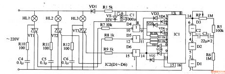
The traffic light controller circuit is composed of the power supply circuit, multivibrator, count divider and lighting control circuit, and it is shown in Figure 7-178. Power supply circuit is composed of the rectifier diode VD1, current limiting resistor Rl, voltage regulator diode VS and filter capacitor Cl. Multivibrator circuit consists of the potentiometer RP, resistors R5, R6, capacitor C2 and the NOT gates Dl-D3 which are inside of the NOT gate integrated circuit IC2 (Dl-D6). Count divider circuit consists of counting / pulse distributor circuit lCI, diodes VD2-VD8 and resistors R2-R4. Lighting control circuit consists of the internal NOT gate D4-D6 of IC2, resistors R7-Rl2, capacitors C4-C6, thyristors VTl-VT3, and indicators HLl-HL3.
(View)
View full Circuit Diagram | Comments | Reading(16)
Motorcycle anti-thief alarm (7)
Published:2011/7/19 20:06:00 Author:TaoXi | Keyword: Motorcycle, anti-thief, alarm
The principle of the circuit
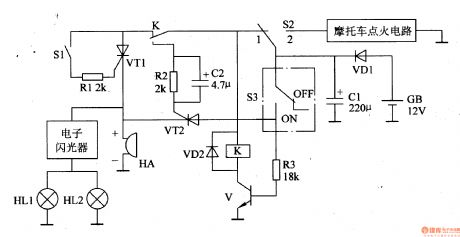
The motorcycle anti-thief alarm circuit is composed of the trigger control circuit and the sound and light alarm circuit, the circuit is as shown in figure 7-90.
The trigger control circuit is composed of the mercury switch S1 (sensor), the function conversion switch S2, the motorcycle lock switch S3, the resistors Rl-R3, the diodes VDl and VD2, the capacitors Cl and C2, the transistor V and the relay K.
The sound and light alarm circuit is composed of the alarm HA, the electronic flasher and the motorcycle turn lights HLl and HL2.
When you stop the motorcycle, you need to set the switch S2 in the position of 1 to make the anti-thief alarm in the alert state, at the time the VTl and VT2 cut off, the HA will not alarm, the HLl and HL2 turn on.
(View)
View full Circuit Diagram | Comments | Reading(682)
The motorcycle anti-theft alarm (6)
Published:2011/7/19 19:55:00 Author:TaoXi | Keyword: motorcycle, anti-theft, alarm
The principle of the circuit
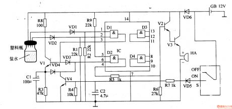
The motorcycle anti-theft alarm circuit is composed of the anti-theft detection control circuit, the switch control circuit and the sound alarm circuit, the circuit is as shown in figure 7-89.
The anti-theft detection control circuit is composed of the sensor (it is composed of the plastic bottle, saline and three electrodes), the diodes VDl and VD2, the resistors Rl and R2, and the D1 of the AND gate IC (Dl-D4).
The sound alarm circuit is composed of the transistors Vl-V3, the D2, the resistors R3, R5, R6, R8, R9, the diodes VD3, VD4, the capacitor Cl and the alarm HA.
The switch control circuit is composed of the diode VD5, the resistor R4, the transistor V4 and the capacitor C2.
(View)
View full Circuit Diagram | Comments | Reading(1347)
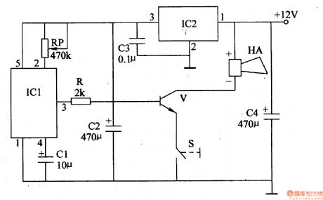
Motor vehicle low temperature starter
Published:2011/7/20 19:10:00 Author:Lucas | Keyword: Motor vehicle , low temperature , starter
The motor low temperature starter circuit consists of control switch S, resistors Rl-R3, capacitor C, transistor V, and time-base integrated circuit IC, and the circuit is shown in Figure 7-175. In the circuit, IC, and Rl, R2, C forme 40OHz pulse oscillator circuit; V and R3 form electronic switching circuit. Rl-R3 select 1/4W metal film resistors. C uses the monolithic capacitors or polyester capacitors. V uses 3DDl5D or 3DDlO2D silicon NPN transistor. IC chooses NE555 time-base integrated circuit. S selects small toggle switch with contact current in 5A.
(View)
View full Circuit Diagram | Comments | Reading(580)
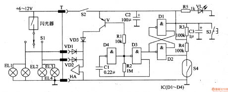
The motorcycle anti-theft alarm (5)
Published:2011/7/19 19:44:00 Author:TaoXi | Keyword: motorcycle, anti-theft, alarm
The principle of the circuit
The motorcycle anti-theft alarm circuit is composed of the trigger circuit, the low frequency oscillation circuit, the switch control circuit and the alarm circuit, the circuit is as shown in figure 7-88.
The trigger circuit is composed of the Dl and D2 (in the four NAND gate ICs (Dl-D4)), the resistors R3 and R4, the capacitor C3 and the mercury switch S4.
The low frequency oscillation circuit is composed of the transistor V, resistor Rl and diode VD3.
The alarm circuit is composed of the high loudness alarm HA and the diodes VDl-VD3.
Sl is the motorcycle turn light switch; ELl-EL4 are the turn lights; S2 is the power supply; S3 is the reset button, VL is the power indicator LED.
(View)
View full Circuit Diagram | Comments | Reading(810)
Motorcycle energy-saving controller
Published:2011/7/20 19:25:00 Author:Lucas | Keyword: Motorcycle , energy-saving controller
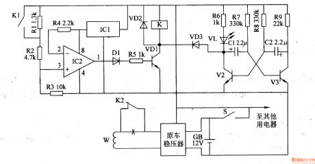
The motorcycle energy-saving controller circuit is composed of the voltage detection control circuit and multivibrator, and the circuit is shown in Figure 7-173. Voltage detection control circuit is composed of the resistors Rl-R5, three-terminal regulator IC lCl, op-amp integrated circuit IC2, diodes VDl, VD2, transistor Vl and relay K. Multivibrator circuit consists of resistors R6-R9, capacitors Cl, C2, light-emitting diode vL and transistors V2, v3. Rl-R9 select 1/4W metal film resistors.
(View)
View full Circuit Diagram | Comments | Reading(735)
The motorcycle anti-theft alarm (4)
Published:2011/7/19 19:36:00 Author:TaoXi | Keyword: motorcycle, anti-theft, alarm
The motorcycle anti-theft alarm is introduced in this article, it uses the private displacement sensor and has the features of high sensitivity, good reliability, low false alarm rate and easy to make.
The principle of the circuit
This motorcycle anti-theft alarm circuit is composed of the integrated vibration displacement sensor (it is composed of the solid acceleration detection sensor and the control integrated circuit) 1Cl, the power supply circuit and the alarm circuit, the circuit is as shown in figure 7-87.
The power supply circuit is composed of the three-port integrated voltage regulator IC2, the filter capacitor C2. The +12V voltage is from the motorcycle battery. The +12V voltage is stabilized by IC2 to become the +6V voltage.
(View)
View full Circuit Diagram | Comments | Reading(2422)
The motorcycle anti-theft alarm (3)
Published:2011/7/19 19:29:00 Author:TaoXi | Keyword: motorcycle, anti-theft, alarm
The motorcycle anti-theft alarm which uses the 555 time-base integrated circuit is introduced in this article, and it can send out the alarm when the thief is moving the motorcycle vertically.
The principle of the circuit
The motorcycle anti-theft alarm circuit is composed of the trigger circuit and the alarm circuit, as the figure 7-85 shows.
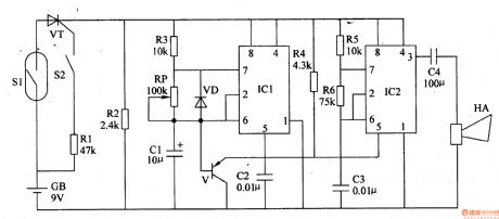
The trigger circuit is composed of the mercury switch Sl, the resistors Rl and R2, the transistor VT.
The alarm circuit is designed as the multivibrator that is composed of the time-base integrated circuit ICl and IC2, the transistor V, the resistors R3-R6, the capacitors Cl-C4, the diode VD.
S2 is the lock control switch, GB is the power supply, HA is the motorcycle electric horn.
(View)
View full Circuit Diagram | Comments | Reading(2254)
| Pages:1480/2234 At 2014611462146314641465146614671468146914701471147214731474147514761477147814791480Under 20 |
Circuit Categories
power supply circuit
Amplifier Circuit
Basic Circuit
LED and Light Circuit
Sensor Circuit
Signal Processing
Electrical Equipment Circuit
Control Circuit
Remote Control Circuit
A/D-D/A Converter Circuit
Audio Circuit
Measuring and Test Circuit
Communication Circuit
Computer-Related Circuit
555 Circuit
Automotive Circuit
Repairing Circuit