
Circuit Diagram
Index 1481
The car electronic fuel-saving device (2)
Published:2011/7/20 1:10:00 Author:TaoXi | Keyword: car, electronic, fuel-saving device
The principle of the circuit
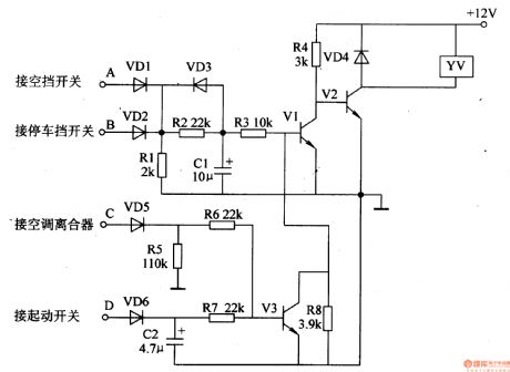
The car electronic fuel-saving device is composed of the diodes VD1-VD6, the resistors R1-R8, the capacitors C1 and C2, the transistors V1-V3 and the electromagnetic valve YV, the circuit is as shown in figure 7-140.
Components selection
R1-R8 are the 1/4W metal film resistors or the carbon film resistors.C1 and C2 are the 16V aluminum electrolytic capacitor.VD1-VD6 are the 1N4007 silicon rectifier diode.V1 and V3 are the S8050 NPN transistors; V2 uses the DDO3 silicon NPN transistor.YU uses the 12V DC electromagnetic valve.
(View)
View full Circuit Diagram | Comments | Reading(1594)
The car electronic fuel-saving device (1)
Published:2011/7/20 1:05:00 Author:TaoXi | Keyword: car, electronic, fuel-saving device
The principle of the circuit
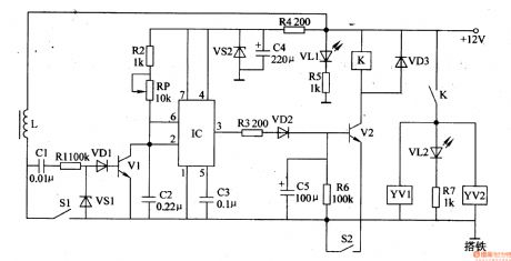
The car electronic fuel-saving device is composed of the transistors Vl and V2, the integrated circuit IC, the relay K, the electromagnetic valves YVl and YV2 and the external components, the circuit is as shown in figure 7-139.
Components selection
The Rl-R3 and R5-R7 are the 1/4W carbon film resistors; the R4 is the lW carbon film resistor.RP is the membrane type variable resistor.Cl-C3 are the monolithic capacitor or the polyester capacitor; the C4 and C5 are the 16V aluminum electrolytic capacitor.VDl-VD3 are the 1N4001 or 1N4007 silicon rectifier diode.The VSl are the 1/4W, 1.8V voltage stabilization diode such as the 1N4614, 2CW5O; VS2 is the 1.5W、6.1V voltage stabilization diode such as the 1N5920.
(View)
View full Circuit Diagram | Comments | Reading(2192)
Motorcycle electronic ignition (2)
Published:2011/7/20 2:33:00 Author:TaoXi | Keyword: Motorcycle, electronic, ignition
The principle of the circuit
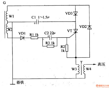
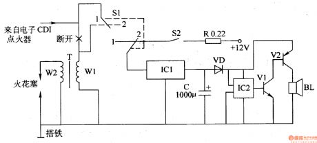
The motorcycle electronic ignition circuit is composed of the resistors R1-R3, the capacitors C1 and C2, the diodes VD1-VD3, the thyristor VT and the magnetor charging coil W1, the control coil W2, the ignition coil T, the circuit is as shown in figure 7-138. The output AC of the magnetor winding W1 is half-wave rectified by VD3 to charge the C1.
Components selection
The R1-R3 use the 1/4W metal film resistor.The C1 uses the 400V CBB capacitor or the polyester capacitor; C2 uses the 5OV aluminum electrolytic capacitor.The VD1-VD3 use the 1N4007 silicon rectifier diode.The VT uses the 2P4M(2A, 400V) thyristor.
(View)
View full Circuit Diagram | Comments | Reading(3142)
Automotive speed limiter
Published:2011/7/20 19:21:00 Author:Lucas | Keyword: Automotive , speed limiter
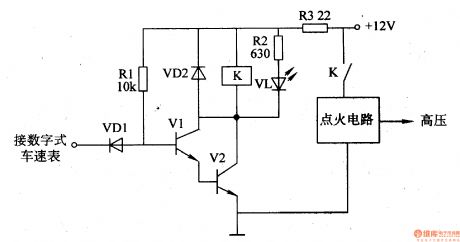
The automotive electronic speed limiter circuit consists of transistors Vl, V2, relay K, resistors Rl-R3, diodes VDl, VD2, and light-emitting diode VL, and the circuit is shown in Figure 7-172. Rl and R2 select 1/4W metal film resistors; R3 selects the lW metal film resistor. VDl and VD2 use 1N4148 silicon switch diode or lN4007 rectifier diode. Vl uses S9013 silicon NPN transistor; V2 uses the S8050 silicon NPN transistor. K selects the 4088 or 4098 12V DC relay.
(View)
View full Circuit Diagram | Comments | Reading(1612)
Motorcycle electronic ignition (1)
Published:2011/7/20 1:48:00 Author:TaoXi | Keyword: Motorcycle, electronic, ignition
The principle of the circuit
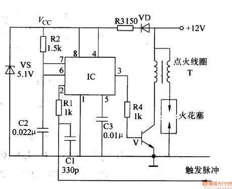
The motorcycle electronic ignition is composed of the time base integrated circuit IC, the switching tube V, the voltage stabilization diode VS, the diode VD and the external components, the circuit is as shown in figure 7-137.
The monostable circuit is composed of the IC, the resistors R1 and R2, the capacitor C1-C3.
The +l2V voltage is reduced and limited by the diode VD and R3, then it is stabilized by VS to be the +5.lV (Vcc) voltage that can be used as the operating voltage of IC.
Components selection
R1, R2 and R4 are the 1/4W carbon film resistors; R3 is the 1W carbon film resistors;C1 is the high-frequency ceramic capacitor; C2 and C3 use the polyester capacitor or monolithic capacitor.
(View)
View full Circuit Diagram | Comments | Reading(6028)
Car multi-function alarm (2)
Published:2011/7/19 22:54:00 Author:TaoXi | Keyword: Car, multi-function, alarm
The principle of the circuit
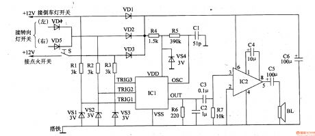
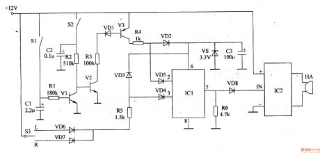
The car multi-function alarm is composed of the trigger control circuit, the voice generator and the audio amplifier output circuit, the circuit is as shown in figure 7-98.
The trigger control circuit is composed of the anti-theft switch S, the diodes VD1-VD5, the resistors R1-R3 and the voltage stabilization diodes VS1-VS3.
The voice generator is composed of the resistors R4-R6, the capacitors Cl, C2, the voltage regulator diode VS4 and the voice integrated circuit lCl.
The audio amplifier output circuit is composed of the audio power amplifier IC IC2, the capacitors C3-C6, the resistor R7 and the speaker BL.
(View)
View full Circuit Diagram | Comments | Reading(561)
Car multi-function alarm (1)
Published:2011/7/19 22:49:00 Author:TaoXi | Keyword: Car, multi-function, alarm
The principle of the circuit
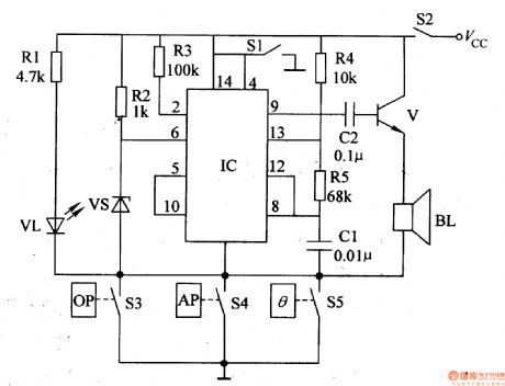
The car multi-function alarm is composed of the dual time-base circuit IC and the external components, the circuit is as shown in figure 7-97.
In this circuit, VL is the alarm indicator light, S1 is the reset switch, S2 is the ignition switch of the car, S3 is the low oil pressure alarm switch, S4 is the low air pressure alarm switch, S5 is the high temperature alarm switch.
Vcc is the output voltage of the car power generator (+13.5V) that can be used as the operating power supply of the alarm, this voltage is lower than 13.5V when the car is in the idle condition; and it is higher or equal to 13.5V when the car is operating above the medium speed.
(View)
View full Circuit Diagram | Comments | Reading(590)
Electric Bicycle electronic governor
Published:2011/7/20 19:17:00 Author:Lucas | Keyword: Electric Bicycle , electronic governor
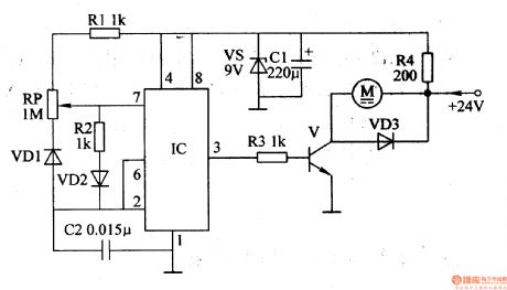
The electric bicycle electronic governor circuit is composed of the regulator filter circuit, pulse oscillation circuit, electronic switching circuit, and the circuit is shown in Figure 7-171. Regulator filter circuit is composed of the resistor R4, Zener diode VS and filter capacitor C1. Pulse oscillation circuit is composed of the resistors Rl, R2, potentiometer RP, diodes VDl, VD2, capacitor C2 and time-base integrated circuit ICl. Electronic switching circuit is composed of the resistor R3, transistor V and diode VD3. Rl-R3 select 1/4W metal film resistors; R4 selects the 1/2W metal film resistor.
(View)
View full Circuit Diagram | Comments | Reading(2499)
Motorcycle anti-thief alarm (13)
Published:2011/7/19 22:33:00 Author:TaoXi | Keyword: Motorcycle, anti-thief, alarm
The principle of the circuit
The motorcycle anti-thief alarm circuit is composed of the anti-thief monitoring circuit, the voice circuit and the high loudness alarm circuit, the circuit is as shown in figure 7-96.
The anti-thief monitoring circuit is composed of the mercury switch S2, the resistors Rl-R4, the capacitors Cl, C2, the transistors Vl-V3 and the diodes VDl.
The voice circuit is composed of the diodes VD2-VD7, the resistors R4-R6, the voltage stabilization diode VS, the filter capacitor C3 and the voice IC ICl.
The high loudness alarm circuit is composed of the diode VD8, the step-up drive module IC2 and the high loudness alarm HA.
(View)
View full Circuit Diagram | Comments | Reading(639)
Motorcycle anti-thief alarm circuit (12)
Published:2011/7/19 22:13:00 Author:TaoXi | Keyword: Motorcycle, anti-thief, alarm circuit
The principle of the circuit
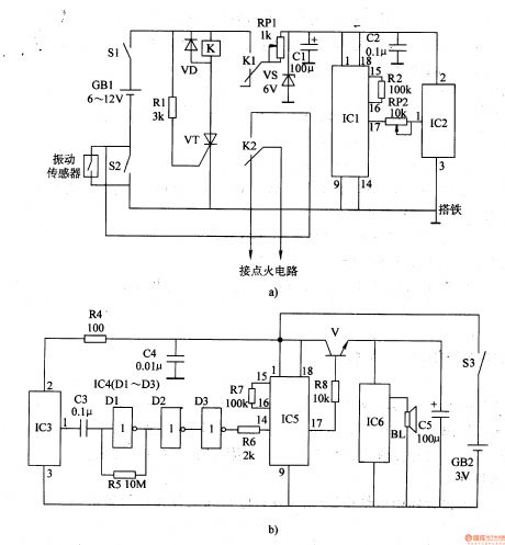
The motorcycle anti-thief alarm circuit is composed of the theft case detection/wireless launch circuit and the wireless receiving alarm circuit, the circuit is as shown in figure 7-95.
The theft case detection/wireless launch circuit is composed of the theft case detection circuit, the control circuit and the wireless launch circuit.The theft case monitoring circuit is composed of the vibration sensor, the power supply switch S1 and the motorcycle lock switch S2.The control circuit is composed of the relay K, the diode VD, the resistors Rl and the thyristor VT.The voltage stabilization filter circuit is composed of the voltage stabilization diode VS and the filter capacitors Cl and C2.The wireless launch circuit is composed of the wireless code integrated circuit ICl, the wireless launch integrated circuit lC2, the resistors R2 and the potentiometer R.
(View)
View full Circuit Diagram | Comments | Reading(684)
Motorcycle anti-thief alarm circuit (11)
Published:2011/7/19 21:47:00 Author:TaoXi | Keyword: Motorcycle, anti-thief, alarm
The principle of the circuit
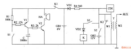
The motorcycle anti-thief alarm circuit is composed of the detection alarm circuit, the charging circuit and the anti-theft control circuit, this circuit is as shown in figure 7-94.
The detection alarm circuit is composed of the mercury switch Sl, the resistors Rl-R3, the capacitor C, the transistors V1, V2 and the high loudness alarm HA.
The charging circuit is composed of the current limiting resistor R4, the diodes VD1 and GB1.
The anti-theft control circuit is composed of the relay K, the anti-theft switch S3, the diode VD2 and the normally open contact point Kz of K.
Rl-R3 use the 1/4W metal film resistors; R4 uses the 3-5W wirewound resistor.C uses the 16V aluminum electrolytic capacitor.VDl and VD2 use the 1N4007 silicon rectifier diode.
(View)
View full Circuit Diagram | Comments | Reading(1736)
Motorcycle anti-thief alarm circuit (10)
Published:2011/7/19 21:23:00 Author:TaoXi | Keyword: Motorcycle, anti-thief, alarm
The principle of the circuit
The motorcycle anti-thief alarm circuit is composed of the anti-theft control switch S1, the mercury switch S2, the current-limit resistor R, the three-port voltage stabilization circuit IC1, the filter capacitor C, the diode VD, the alarm sound integrated circuit lC2, the transistors V1 and V2, the speaker BL, the circuit is as shown in figure 7-93.
Components selection
R uses the 5W fusing resistor.C uses the 16V aluminum electrolytic capacitor.VD uses the 1N4001 or 1N4007 silicon rectifier diode.Vl uses the S9013 silicon NPN transistor; V2 uses the S8550 silicon PNP transistor.lCl uses the LM7805 three-port voltage integrated circuit; IC2 uses the KD9561 four tones sound IC.
(View)
View full Circuit Diagram | Comments | Reading(615)
Motorcycle anti-thief alarm circuit (9)
Published:2011/7/19 21:05:00 Author:TaoXi | Keyword: Motorcycle, anti-thief, alarm circuit
The principle of the circuit
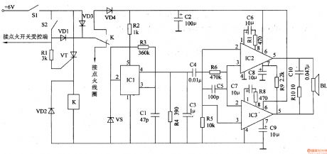
The motorcycle anti-thief alarm circuit is composed of the detection control circuit, the voice generator and the audio power amplifier output circuit, the circuit is as shown in figure 7-92.
The detection control circuit is composed of the power switch S1, the mercury switch S2, the diodes VDl-VD3, the resistor RI, the transistor VT and the relay K.
The voice generator circuit is composed of the diode VD4, the voltage stabilization diode VS, the resistors R2 and R3, the capacitor Cl and the analog voice integrated circuit ICl.
The udio power amplifier output circuit is composed of the audio power amplifier integrated circuits IC2 and IC3, the resistors R4-Rl0, the capacitors C2-C10 and the speaker BL.
(View)
View full Circuit Diagram | Comments | Reading(659)
Motorcycle anti-thief alarm circuit (8)
Published:2011/7/19 20:45:00 Author:TaoXi | Keyword: Motorcycle, anti-thief, alarm circuit

The principle of the circuit
The motorcycle anti-thief alarm circuit is composed of the anti-theft detection circuit, the control circuit, the sound generator, the audio oscillator and the power amplifier output circuit, the circuit is as shown in figure 7-91.
The anti-theft detection circuit is composed of the piezoelectric vibration sensor BC, the resistors R3-R7, R18, the capacitors Cl-C3, the diodes VDl-VD3 and the D3, D4 of the four NAND gate IC (Dl-D4).
The control circuit is composed of the transistors Vl and V3, the resistors Rl, R2, Rll-R13.
The sound generator is composed of the resistors R8 and R9, the capacitor C4 and the sound integrated circuit IC2.
(View)
View full Circuit Diagram | Comments | Reading(2602)
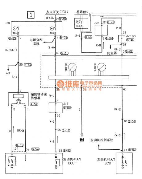
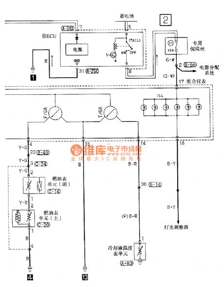
Southeast Ling Sheng instrument electric system circuit
Published:2011/7/20 21:40:00 Author:leo | Keyword: Instrument, electric system
View full Circuit Diagram | Comments | Reading(982)
Electromagnetic therapeutic apparatus (1)
Published:2011/7/20 1:19:00 Author:TaoXi | Keyword: Electromagnetic, therapeutic, apparatus
The principle of the circuit
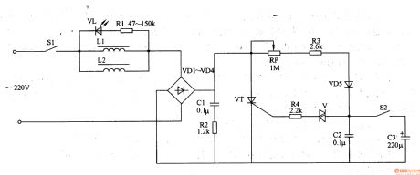
The electromagnetic therapeutic apparatus circuit is composed of the power switch S1, the electromagnetic coils L1 and L2, the rectifier diodes VD1-VD5, the LED VL, the resistors Rl-R4, the potentiometer RP, the thyristor VT, the two-way trigger diode V, the capacitors C1-C3 and the constant magnetic/pulse selector switch S1, the circuit is as shown in figure 9-13.
Components selection
The R1-R4 use the 1/4W metal film resistor.The RP uses the organic solid potentiometer.The C1 and C2 use the 400V CBB capacitor or the polyester capacitor; C3 uses the 5OV aluminum electrolytic capacitor.The VD1-VD4 use the 5A, 400V silicon rectifier diode; VD5 uses the 1N4007 silicon rectifier diode.
(View)
View full Circuit Diagram | Comments | Reading(740)
Southeast Ling Sheng dormer electric system circuit
Published:2011/7/20 21:50:00 Author:leo | Keyword: Dormer, electric system

View full Circuit Diagram | Comments | Reading(782)
Mine charging indicator
Published:2011/7/20 2:53:00 Author:TaoXi | Keyword: Mine, charging, indicator
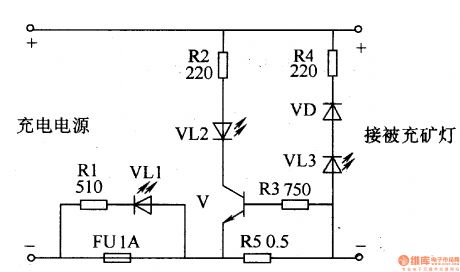
The principle of the circuit
The mine charging indicator is composed of the electrical resistor R1-R5, the fuse FU, the circuit is as shown in figure 8-36.
When the storage battery is charging, the V conducts, the VL2 turns on. When the storage battery is full, the V cuts off, the VL2 turns off.
When the polarity connection of the storage battery is correct, the VL3 will not light. If the polarity connection of the storage battery is reverse, the VL will turn on to send out the yellow alarm signal.
Components selection
The R1-R4 use the 1/4W metal film resistor; R5 use the 2W wirewound resistor.The VD uses the 1N4007 rectifier diode.The VL1-VL3 use the φ5mm high-brightness light-emitting diode.The V uses the S8050 silicon NPN transistor.
(View)
View full Circuit Diagram | Comments | Reading(1603)
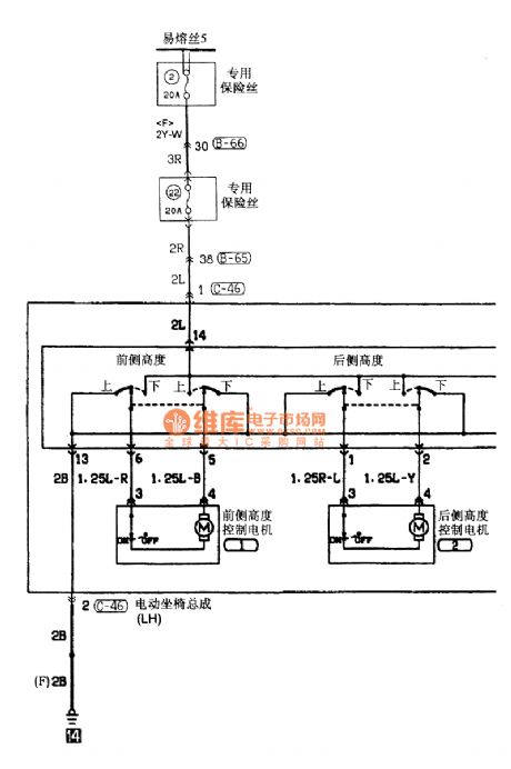
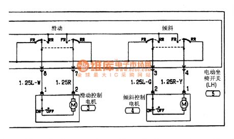
Southeast Ling Sheng power seat electric system circuit
Published:2011/7/20 21:51:00 Author:leo | Keyword: Power seat, electric system
View full Circuit Diagram | Comments | Reading(448)
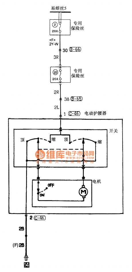
Southeast Ling Sheng waist-protecting appliance electric system circuit
Published:2011/7/20 21:54:00 Author:leo | Keyword: Waist-protecting appliance, electric system
View full Circuit Diagram | Comments | Reading(659)
| Pages:1481/2234 At 2014811482148314841485148614871488148914901491149214931494149514961497149814991500Under 20 |
Circuit Categories
power supply circuit
Amplifier Circuit
Basic Circuit
LED and Light Circuit
Sensor Circuit
Signal Processing
Electrical Equipment Circuit
Control Circuit
Remote Control Circuit
A/D-D/A Converter Circuit
Audio Circuit
Measuring and Test Circuit
Communication Circuit
Computer-Related Circuit
555 Circuit
Automotive Circuit
Repairing Circuit