
Circuit Diagram
Index 1483
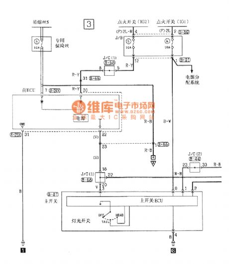
Southeast Ling Sheng tail lamp,position lamp and license lamp electric system circuit
Published:2011/7/20 20:32:00 Author:leo | Keyword: Tail lamp, position lamp, license lamp


View full Circuit Diagram | Comments | Reading(785)
74 series digital circuit 74HC237, 74ALS237 3-8 line decoders (with address latch)
Published:2011/7/15 4:45:00 Author:TaoXi | Keyword: 74 series, digital circuit, 3-8 line, decoders, address latch
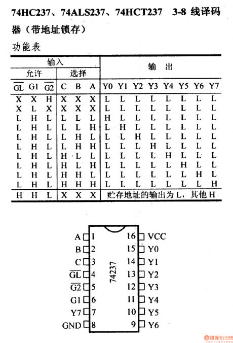
The 74 series digital circuit 74HC237, 74ALS237 3-8 line decoders (with address latch)
(View)
View full Circuit Diagram | Comments | Reading(1492)
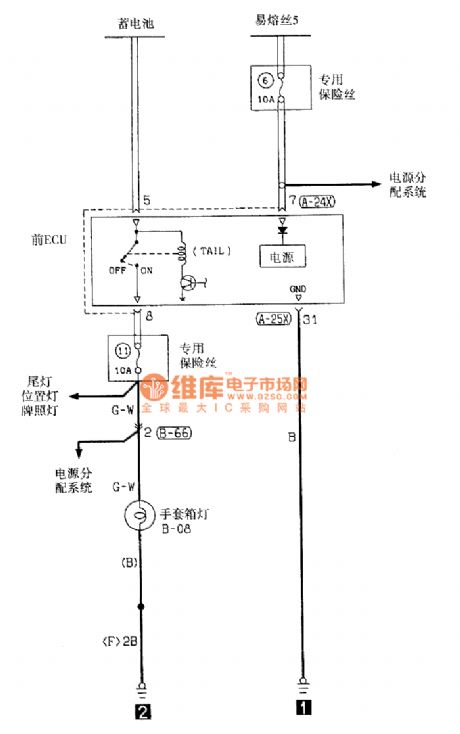
Southeast Ling Sheng glove box lamp electric system circuit
Published:2011/7/20 21:10:00 Author:leo | Keyword: Glove box lamp, electric system
View full Circuit Diagram | Comments | Reading(644)
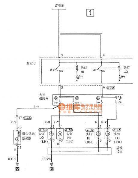
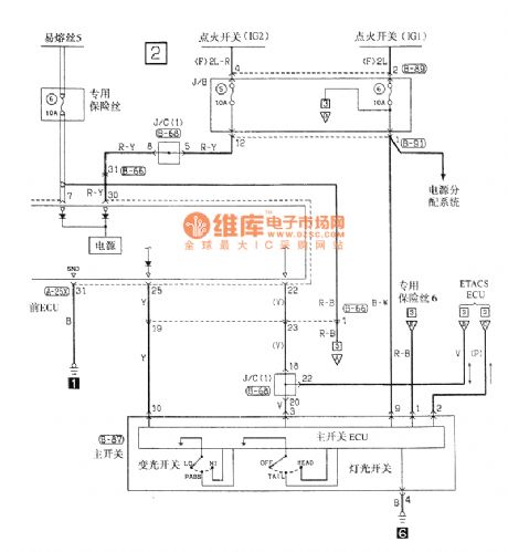
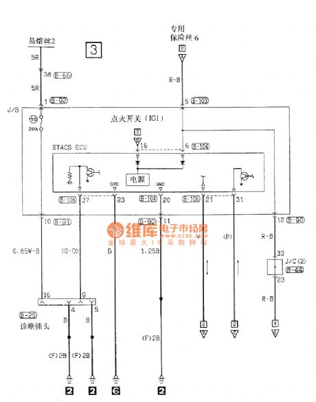
Southeast Ling Sheng head lamp electric system circuit
Published:2011/7/20 21:04:00 Author:leo | Keyword: Head lamp, electric system
View full Circuit Diagram | Comments | Reading(680)
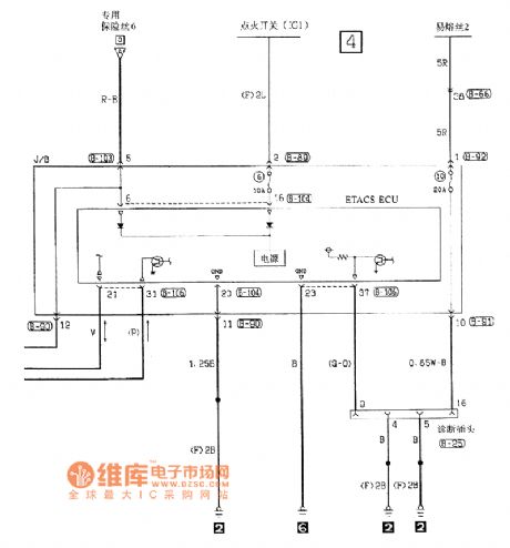
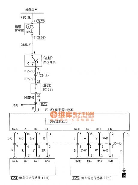
Southeast Ling Sheng car reverse radar electric system circuit
Published:2011/7/20 21:08:00 Author:leo | Keyword: Car reverse radar, electric system
View full Circuit Diagram | Comments | Reading(716)
74 series digital circuit 74221 dual monostable multivibrator (with the Schmidt trigger)
Published:2011/7/15 4:50:00 Author:TaoXi | Keyword: 74 series, digital circuit, dual, monostable, multivibrator, Schmidt trigger
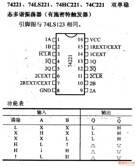
74221, 74LS221, 74HC221 and 74C221 dual monostable multivibrators (with the Schmidt trigger)
(View)
View full Circuit Diagram | Comments | Reading(2154)
74 series digital circuit 74193, 74L193 presetable 4-bit binary system synchronous reversible counters (double clock with clear function)
Published:2011/7/15 5:02:00 Author:TaoXi | Keyword: 74 series, digital circuit, presetable, 4-bit, binary system, synchronous reversible counter, double clock, clear function
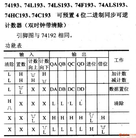
The 74 series digital circuit presetable 4-bit binary system synchronous reversible counters (double clock with clear function)
(View)
View full Circuit Diagram | Comments | Reading(4921)
74 series digital circuit 74185A binary system BCD converter
Published:2011/7/19 1:38:00 Author:TaoXi | Keyword: 74 series, digital circuit, binary system, BCD, converter
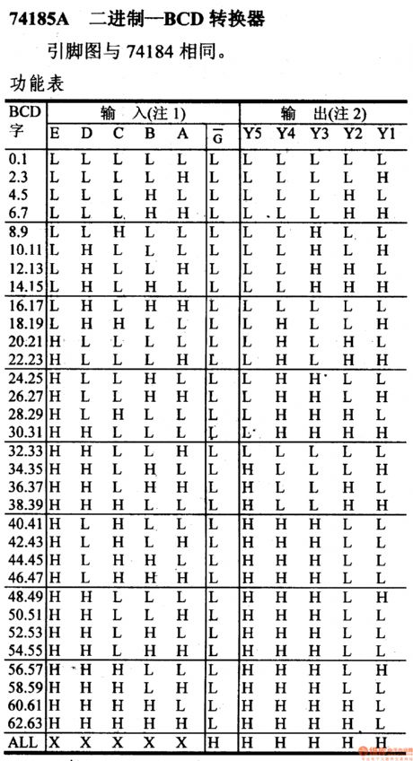
74 series digital circuit 74185A binary system BCD converter
(View)
View full Circuit Diagram | Comments | Reading(2348)
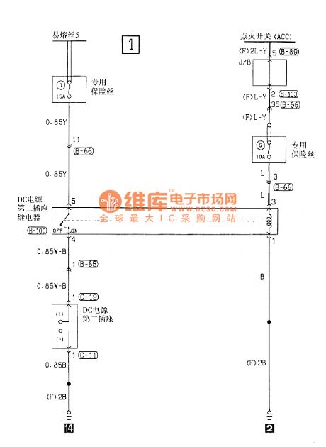
Southeast Ling Sheng the second power socket electric system circuit
Published:2011/7/20 22:01:00 Author:leo | Keyword: Power socket, electric system
View full Circuit Diagram | Comments | Reading(705)
74 series digital circuit 74184 binary system BCD converter
Published:2011/7/19 1:44:00 Author:TaoXi | Keyword: 74 series, digital circuit, binary system, BCD, converter
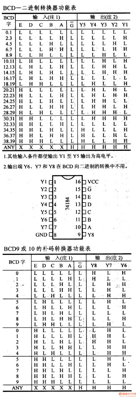
1.The other input conditions make the Y6, Y7 and Y8 output the high level.2.The outputs Y1-Y5 will not be used in the BCD9 or BCD10's complement conversion.3.When it is used as the complement inverter, the input E is used as the mode control, when this port's output is low, it produces the complement number of BCD9, when this port's output is high, it produces the complement number of BCD10.
(View)
View full Circuit Diagram | Comments | Reading(2006)
74 series digital circuit 74H183, 74LS183 dual carry save adder
Published:2011/7/19 1:36:00 Author:TaoXi | Keyword: 74 series, digital circuit, dual carry, save adder
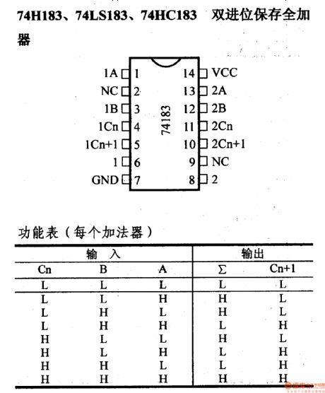
74 series digital circuit 74H183, 74LS183 dual carry save adder
(View)
View full Circuit Diagram | Comments | Reading(2663)
IX0187PA (TV and audio equipment) 30 functions infrared remote control launch circuit
Published:2011/7/21 1:37:00 Author:TaoXi | Keyword: TV, audio equipment, 30 functions, infrared, remote control, launch circuit
The IX0187PA has the same features, pin arrangement, pin functions, absolute maximum ratings, electrical specifications, logic diagram and the typical applications with the M58484P, so they can directly exchange. (View)
View full Circuit Diagram | Comments | Reading(971)
IX033lPA (video tape recorder) infrared remote control launch circuit
Published:2011/7/20 19:08:00 Author:TaoXi | Keyword: video tape recorder, infrared, remote control, launch circuit
The IX033lPA has the same features, pin arrangement, pin functions, absolute maximum ratings, electrical specifications, logic diagram and the typical applications with the LR3710AM, so they can directly exchange. (View)
View full Circuit Diagram | Comments | Reading(815)
The heavy current and high efficiency switch constant voltage power supply circuit formed by LAS6351
Published:2011/7/20 23:40:00 Author:leo | Keyword: Heavy current, high efficiency
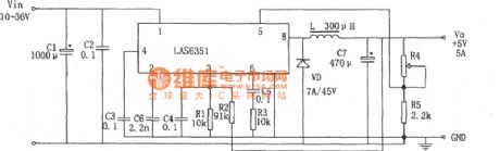
 As the picture shows, it is a heavy current and high power switch constant voltage power supply circuit formed by LAS6351. LAS6351 is a kind of switch integrated AVR which has heavy current and adjustable impulse width. It can output 2.5 V to 5 V voltage under 3 A to 8 A constant load current. It has soft boot and over load, over voltage as well as over current protecting circuits. Its efficiency can reach 90%. Because of the 200kHz efficiency, the cost of outer filter is lowered down. (View)
View full Circuit Diagram | Comments | Reading(816)
IX0348PA (video tape recorder) infrared remote control launch circuit
Published:2011/7/20 19:09:00 Author:TaoXi | Keyword: video tape recorder, infrared, remote control, launch circuit
The IX0348PA has the same features, pin arrangement, pin functions, absolute maximum ratings, electrical specifications, logic diagram and the typical applications with the LR3709, so they can directly exchange. (View)
View full Circuit Diagram | Comments | Reading(837)
Ix0478PA (video tape recorder) infrared remote control launch circuit
Published:2011/7/20 19:10:00 Author:TaoXi | Keyword: video tape recorder, infrared, remote control, launch circuit
The IX0478PA has the same features, pin arrangement, pin functions, absolute maximum ratings, electrical specifications, logic diagram and the typical applications with the LR3714M, so they can directly exchange. (View)
View full Circuit Diagram | Comments | Reading(856)
Simple multi-function charger circuit
Published:2011/7/15 4:09:00 Author:TaoXi | Keyword: Simple, multi-function, charger
Operating principle:
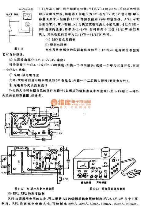
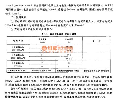
This circuit has four parts: the charging circuit, the discharging circuit, the power supply circuit and the lighting circuit, as shown in figure 5-8. The power supply circuit part can output the 6V, 4.5V, 3V voltage, the output current is 500mA, it can be used to provide the recorder or be used as the power supply. The 500mA output current is limited by the transformer power, if we use the 10W transformer, the output current can be 1A. The lighting circuit uses the 6.3V/100mA flashlamp that can be used in the low-light illumination at night. The power supply circuit and the lighting circuit are additional. Here I mainly introduce the charging circuit and discharging circuit.
(View)
View full Circuit Diagram | Comments | Reading(712)
Aiwa J303g charger electricity principle diagram (double 1.2V quick charger circuits)
Published:2011/7/18 20:29:00 Author:TaoXi | Keyword: Aiwa, charger, electricity, principle diagram, double, 1.2, quick charger

In figure 2-17, the circuit uses the half-wave rectified pulsating current to charge the Nickel-cadmium batteries, the charging voltage has two stages. At the beginning of charging, S is in the 1 stage. When the battery is full, the light-emitting diode darkens gradually, so we need to choose the stage 2 to charge the battery in floating charging mode.
In order to speed up the charging speed, some chargers use the electronic circuit to realize the fast charging, it promotes the internal chemical reaction process of the battery by using the large current charging and the large current discharging. View from the charging effect, the common charge effect is better than the quick charge.
(View)
View full Circuit Diagram | Comments | Reading(658)
The low drift constant current circuit formed by MIC2951
Published:2011/7/20 22:11:00 Author:leo | Keyword: Low drift, constant current

As the picture shows, it is a low drift constant current circuit formed by MIC2951. Its output current is 1.23 V/R. In order to make the output current of MIC2951 lower than 150 mA, the accuracy of R should be 1%.
(View)
View full Circuit Diagram | Comments | Reading(690)
LM317 integrated circuit charger circuit
Published:2011/7/18 21:19:00 Author:TaoXi | Keyword: integrated, charger circuit
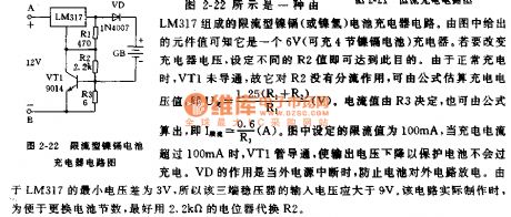
The constant current charging circuit which is composed of the three-port voltage stabilizer is as shown in figure 2-21. Because the electric potential difference of the LM317's pin-1 and pin-2 is 1.25V, if we ignore the shunting effects of R3, R1, LED, the potentiometer R2 can adjust the charging current value, the constant current value I=1.25/R2. In actual use, the R2 always uses the 1W resistance. When the R2 is 25Ω/1W, the charging current of the battery is about 50mA. The charging indicator circuit is composed of the resistor R1 and LED, if we choose the appropriate value of R3, when the battery has the required charging voltage, the VT1 will cut off, the LED will turn off. This circuit can charge more than four No.5 nickel-cadmium batteries.
(View)
View full Circuit Diagram | Comments | Reading(930)
| Pages:1483/2234 At 2014811482148314841485148614871488148914901491149214931494149514961497149814991500Under 20 |
Circuit Categories
power supply circuit
Amplifier Circuit
Basic Circuit
LED and Light Circuit
Sensor Circuit
Signal Processing
Electrical Equipment Circuit
Control Circuit
Remote Control Circuit
A/D-D/A Converter Circuit
Audio Circuit
Measuring and Test Circuit
Communication Circuit
Computer-Related Circuit
555 Circuit
Automotive Circuit
Repairing Circuit